HAL Id: hal-01856560
https://hal.archives-ouvertes.fr/hal-01856560
Submitted on 4 Mar 2021
HAL is a multi-disciplinary open access
archive for the deposit and dissemination of
sci-entific research documents, whether they are
pub-lished or not. The documents may come from
teaching and research institutions in France or
abroad, or from public or private research centers.
L’archive ouverte pluridisciplinaire HAL, est
destinée au dépôt et à la diffusion de documents
scientifiques de niveau recherche, publiés ou non,
émanant des établissements d’enseignement et de
recherche français ou étrangers, des laboratoires
publics ou privés.
A new experimental database for the investigation of
soot in a model scale swirled combustor under perfectly
premixed conditions
Mathieu Roussillo, Philippe Scouflaire, Nasser Darabiha, Sébastien Candel,
Benedetta Franzelli
To cite this version:
Mathieu Roussillo, Philippe Scouflaire, Nasser Darabiha, Sébastien Candel, Benedetta Franzelli. A
new experimental database for the investigation of soot in a model scale swirled combustor under
perfectly premixed conditions. ASME Turbo Expo 2018, Jun 2018, Oslo, Norway.
�10.1115/gt2018-76205�. �hal-01856560�
A NEW EXPERIMENTAL DATABASE FOR THE INVESTIGATION OF SOOT IN A
MODEL SCALE SWIRLED COMBUSTOR UNDER PERFECTLY PREMIXED RICH
CONDITIONS
M. Roussillo§‡∗, P. Scouflaire§, N. Darabiha§, S.Candel§, B. Franzelli§, §Laboratoire EM2C, CNRS, CentraleSup ´elec, Paris-Saclay
3 Rue Joliot Curie 91192 Gif-sur-Yvette Cedex
France ‡Air Liquide
R&D Paris Saclay, 1 Chemin de la porte des Loges 78354 Jouy-en-Josas, France
ABSTRACT
Soot production in turbulent flames represents an urgent is-sue for applied systems and raises a range of fundamental chal-lenges. Most of the literature effort on this question has been car-ried out on non-premixed turbulent flames, where mixing plays a dominant role. It is however interesting to see if soot production can be investigated in a premixed turbulent flame configuration, thus eliminating the role of mixing in this process. It is shown in the present article that this can be accomplished by making use of rich swirled ethylene/air flames under perfectly-premixed rich conditions established in a confined combustor operating at atmospheric pressure. Quantitative measurements of the soot volume fraction ( fv) are carried out by the Laser Induced In-candescence (LII) technique. Although the soot volume fraction levels are one or two orders of magnitude lower than those found in non-premixed flames, it is shown that detection is feasible and that this configuration may be used to analyze effects on soot production of operating parameters such as the equivalence ra-tio, the power level or the wall temperature. The observed trends are interpreted numerically by considering an idealized model of a rich premixed burner-stabilized stagnation flame. This config-uration is here calculated with a detailed kinetic scheme in com-bination with a soot sectional model. This description is able to
∗
Corresponding author: mathieu.roussillo@centralesupelec.fr
account for some of the trends observed experimentally and indi-cates in particular how an increase in the wall temperature may increase the soot volume fraction as it is effectively observed in the experiment. The model predicts that the soot volume frac-tion level increases for high equivalence ratios. This finding is in disagreement with the experimental observations on this swirled flame, which exhibits a maximum soot volume fraction for φ = 2.1 for all the considered flame powers. This indicates that com-plex interactions take place between soot, flame, turbulence and thermal environment and that the investigation of these processes will require a comprehensive turbulent simulation. This may be guided by the database developed in the present experimental effort.
INTRODUCTION
Soot emission is a major issue for society due to its adverse effects on climate [1] and human health [2]. A better understand-ing of the processes governunderstand-ing its production and destruction is needed in order to control emissions by the turbulent flames that are mainly used in transportation systems and industrial facilities. Soot modeling is a promising way towards achieving these goals but is still not capable of precisely predicting soot production due to the extreme complexity of soot nature and its numerous interactions with turbulence, thermal environment
and flame structure. In order to improve and validate soot modeling, it is important to develop well controlled laboratory-scale experiments on sooting flames allowing quantitative investigations of soot production and its relation with flame structure and operating conditions. For this, many experimental investigations have focused on laminar non-premixed and premixed sooting flames [3–6]. Laminar pulsating flames have also been considered [7–14] to close the gap between laminar and turbulent flame configurations, enabling the study of the effect of well-controlled flow variations on soot emission. As for the turbulent domain, most of the fundamental studies focus on turbulent jet diffusion flames [15, 16] but these open flames differ quite notably from the confined flames that are usually found in automotive, aircraft or industrial systems. There are however investigations like that of Geigle et al. [17, 18] that examine soot formation in turbulent non-premixed flames stabilized by a swirling flow and established under elevated pressures, which better correspond to the conditions found in aero-engine combustors. These investigations have provided considerable insight on soot production in this type of flames and include quantitative measurements of the soot volume fraction and its evolution with operating parameters. Nevertheless, the non-premixed situation is essentially controlled by the quality of mixing between fuel and oxidizer inducing local mixture inhomogeneities that dominate the process and complicate the modeling of soot production. Although perfectly-rich turbulent flames are less well documented1, they are of considerable interest for different reasons. First, since fuel and oxidizer are initially mixed, one may directly examine turbulence effects on soot production independently of mixing. Second, perfectly premixed conditions represent an easier configuration for vali-dation of numerical models compared to the non-premixed case. Finally, the investigation of soot production in this combustion mode is of relevance for the Rich-Quench-Lean concept, that constitutes a possible alternative for reduction of NOxemission in gas turbines combustors. These considerations have led to the design of a new experimental facility (EM2Soot) at the EM2C, CNRS laboratory, allowing the investigation of soot production in perfectly-premixed swirled flames over a broad range of rich conditions (1.3 < φ < 2.8) and operating at atmospheric pressure.
In this paper, the experimental setup is first presented to-gether with the optical system used to perform Laser Induced Incandescence (LII) measurements of the soot volume fraction.
1To our knowledge, only one work exists on turbulent premixed sooting
flame [19]. This case presents a large eddy simulation of a turbulent non-confined premixed flame that considers effects of turbulence and equivalence ratio on soot production. Unfortunately, the validity of the conclusions is limited due to the absence of experimental data. There are apparently no other numerical or ex-perimental studies in the literature that deal with turbulent perfectly-premixed sooting flames.
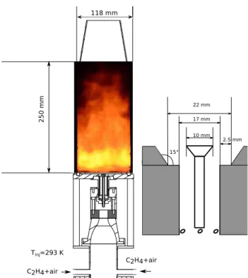
FIGURE 1: EM2Soot design (left) with a schematic of the injec-tor (right).
Effects of flow rate, equivalence ratio and wall thermal condi-tions on soot production are examined both from direct images of the flame broadband emission of light and from LII measure-ments. The observed trends are then interpreted by making use of a simplified model relying on a burner-stabilized stagnation (BSS) flame, i.e. a strained premixed laminar flames formed in the vicinity of a stagnation plane. These flames are simulated us-ing a detailed gas kinetic mechanism and a soot sectional model. This model cannot reflect all the complexities of the turbulent premixed flame, however it captures some of the trends observed experimentally.
EXPERIMENTAL SETUP EM2Soot design
The EM2Soot burner, schematically represented in Fig. 1, comprises three parts: the plenum, the injector and the combus-tion chamber. Ethylene and air flows at ambient temperature (Tin j= 293 K) are mixed in the upstream manifold. The mix-ture is injected at the bottom of the plenum through two radial tubes of diameter 12 mm. A honeycomb is inserted in the in-jection duct to break down any residual structure resulting from the interaction of the two radial injected jets. The fresh mix-ture then passes through a radial swirler (swirl number S= 0.7) before reaching the injector end-piece which is also sketched in
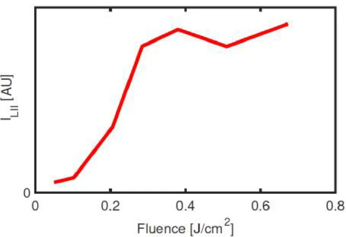
FIGURE 2: Evolution of LII signal with laser fluence for the EM2Soot burner. Data from the region of interest highlighted in Fig. 3a are averaged spatially and temporally over 400 images.
Fig. 1 (right). Due to the lack of similar experiments in the lit-erature, the stabilization of a rich perfectly-premixed flame re-quired some care and resulted from an iterative variation of the geometry. The final configuration comprises a 10 mm diameter bluff-body that favors the stabilization of the flame. The combus-tion chamber measures 250 mm in height and has a square cross section of 118×118 mm2. Four quartz windows (90 mm×250 mm×3 mm) are mounted between four metal bars. Twelve ther-mocouples are inserted at different locations of the chamber: in the bluff body (1 thermocouple), in the bottom of the chamber (3 thermocouples) and along one side bar (8 thermocouples). These sensors measure the temperature on the inner side of the cham-ber and give a rough idea of the gas temperature in the vicinity of the wall. A convergent nozzle is installed at the exit of the combustion chamber fed by the ambient air, allowing the stabi-lization of a second flame that burns the hot exhaust of the rich premixed flame (unburnt gases, hydrogen, carbon monoxide,..). The second flame does not influence the primary combustion re-gion because the chamber is sufficiently long and because of the convergent nozzle that avoids a possible entrainment and recir-culation of ambient air. Therefore, this second flame is of no relevance to this work. Bronkhorst El-Flow electronic flow con-trollers are used to determine the mass flow rate with a calculated uncertainty of 0.3% FS (Full Scale). The burner is designed to stabilize the flame for a wide range of experimental conditions, in terms of flame power release and equivalence ratio φ . As the EM2Soot burner is used under rich conditions, two definitions for the power of the flame can be provided:
- the total flame power, Ptot = PCIC2H4m˙F, where ˙mF is the
total flow rate of ethylene injected in the burner. - the premixed flame power Pprem= PCIC2H4m˙
P
F, where ˙mPF corresponds to the effective flow rate of ethylene that is con-verted by the premixed flame: ˙mPF = ˙mO2/s, with s = 3.43
the stoichiometric coefficient for ethylene/air combustion and ˙mO2the total flow rate of oxygen injected in the burner.
One may note that the equivalence ratio, the premixed flame power and the total flame power are linked through:
φ= sm˙F ˙ mO2 =
Ptot
Pprem, (1)
so that only two of these parameters are needed to define the operating conditions of the system. It is convenient to use the equivalence ratio φ and the premixed flame power Ppremfor that purpose. One may note that the power released in the premixed flame is essentially proportional to the mass flow rate of oxy-gen that is approximately equal to the total mass flow rate of air (since the mass flow rate of ethylene is negligible with respect to the mass flow rate of air). The power release then defines an injection velocity into the system and fixes a Reynolds number. It is also worth noting that Ppremonly provides an estimate of the heat release because the final state of the burnt gases corresponds to an equilibrium of gases like CO, H2and other unburnt hydro-carbons. It will be shown in the following section that the thermal environment has a strong impact on soot production in the sys-tem. This may be characterized by an inner wall temperature Tc measured by a thermocouple inserted in one of the side bars at mid height (113 mm above the chamber backplane, i.e. the bot-tom of the burner close to the bluff-body). In conclusion, results will be presented in terms of equivalence ratio φ , premixed flame power Ppremand characteristic wall temperature Tc.
Laser Induced Incandescence (LII) optical setup
Two-dimensional fields of soot volume fraction are obtained in this work by making use of LII measurements. For this, a laser sheet focused on the burner central axis is obtained from a Nd:YAG laser (1064 nm, 10 Hz). The sheet is 0.35 mm thick and 7 cm wide. The laser fluence is set to approximately 0.45 J/cm2with a shot duration of ≈ 8 ns. This value belongs to the “plateau” region (fluence> 0.3 J/cm2) of the LII signal [20] for the considered configuration, as shown in Fig. 2.
The LII signal is recorded by an intensified CCD camera (Princeton, PI-MAX 3, 1024 × 1024 pixels) equipped with a lens (Nikkor 50 mm f/2) and a bandpass filter centered at 425 nm (50 nm FWHM). The band pass filter is chosen in order to reduce parasitic C2Swan band emission and flame luminos-ity [21]. The camera gate width is set to 100 ns and temporal syn-chronization between the laser and the camera is obtained with an Oxford DG535 Digital Delay generator. The gate width has been chosen to maximize the signal to noise ratio for every op-erating condition assuring a reliable proportionality between LII signals and soot volume fraction [22]. Spatial resolution of the camera is 100 pixels for 1 cm (∆x= 0.1 mm). The calibration
a. -2 0 2
x [cm]
7 6 5 4 3 2 1y [cm]
0.01 0.02 0.03 0.04 0.05 0.06 0.07 0.08 b. -2 0 2x [cm]
7 6 5 4 3 2 1y [cm]
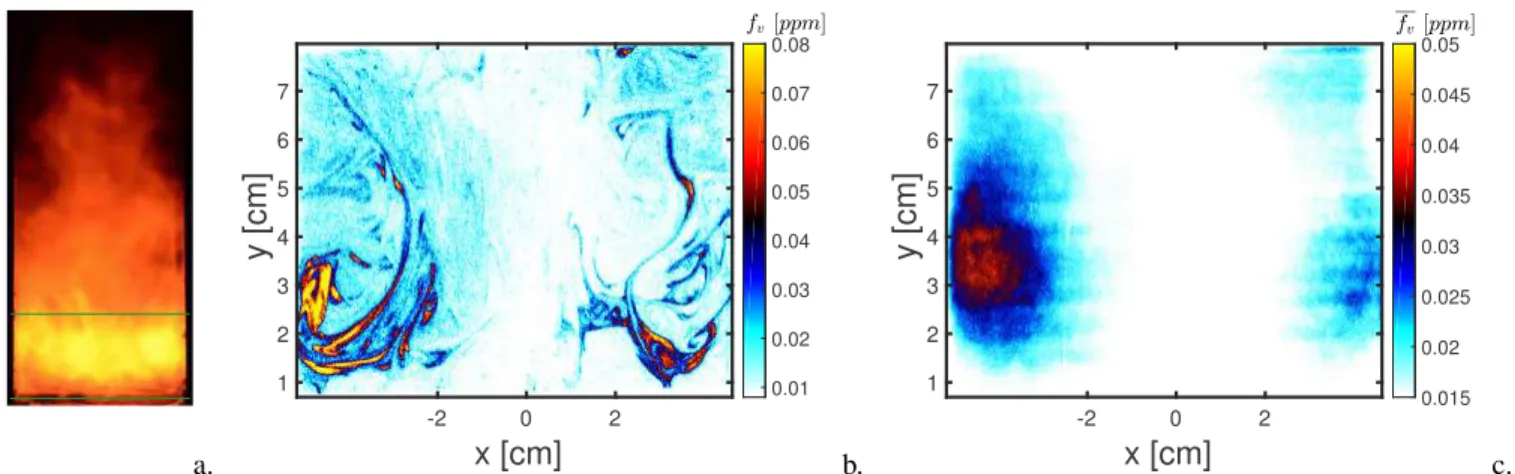
0.015 0.02 0.025 0.03 0.035 0.04 0.045 0.05 c.FIGURE 3: Illustrations of the reference flame (φ = 2.1, Pprem= 7.14 kW and Tc= 573 K). a) Flame luminosity; b) instantaneous field of fvfrom LII; c) time-averaged soot volume fraction from LII. The region of interest is visualized between the green lines in a).
of the LII signal was performed on the basis of recent investi-gations [23, 24] relying on the Modulated Absorption Emission technique (MAE [25, 26]) applied to a laminar diffusion flame [3]. The quantitative interpretation of the data requires a value of the soot complex refractive index and this quantity was taken to be E(m, 645 nm) = 0.38. This value yields consistent results in comparative measurements of soot volume fractions on the lam-inar flame but it should be noted that, due to the high variability of this refractive index [27], this choice may induce errors on the quoted volume fractions fvthat may be up to a factor two or three [24]. A sophisticated approach to estimate the uncertainties of the measured soot volume fraction has been proposed in [28] based on a Monte-Carlo approach. Here, this error is estimated in a simpler way by considering the main phenomena that affect the calibration process in the laminar diffusion flame: sensitivity of the flame to flow rate variations and laser fluence fluctuations, uncertainties in the soot refractive index and variability depend-ing on the calibration procedure [23, 24]. In addition to the LII measurements, images of the flame broadband emission of light are captured with a Nikkon D-7000 with an exposure time of 2 ms. This camera records visible light in a wavelength range ex-tending from 420 to 690 nm [29]. These light emission images will be used to illustrate the effect of the equivalence ratio, flame power and thermal environment on soot volume fraction even if it should be reminded that the flame broadband emission of light is strongly related to the flame/soot temperature via the Planck’s law. An example of the results obtained with the experimental facility will be discussed in the next section.
Reference case
In this work, many operating conditions will be considered in terms of equivalence ratio and flame power. The soot structure is similar for all the investigated flames. Therefore, it is inter-esting to first look at a nominal case corresponding to the set of
φ Tc[K] Pprem[kW] Ptot[kW] m˙F[g/s] m˙air[g/s] 2.1 573 7.14 15 0.319 2.23
TABLE 1: Operating conditions for the reference flame.
conditions summarized in Table 1.
In Fig. 3a, most of the light is emitted from the lower part of the chamber, where a yellow flame characterized by a high luminosity is observed. This image can be interpreted as a first indication of soot presence and localization. For the following discussion, only the region of interest, identified by the green line drawn in Fig. 3a will be considered. The LII signal is stored into a 3-D matrix: fv(x, y,t) ∈ RNx×Ny×Nt
+ , with Nx= 1024, Ny= 1024 and Nt= 400. The time-average operator ¯· is defined as:
¯fv(x, y) = 1 Nt Nt
∑
t fv(x, y,t). (2)Time-averaged levels of soot volume fraction are calculated over 400 images, a sufficiently large number of instantaneous fields assuring that the time-averaged value is converged. This implies an acquisition time of 40 s (images are captured at 10 Hz), suf-ficiently small to prevent the obscuration of the quartz window by soot particles. An instantaneous soot volume fraction field obtained via LII is displayed in Fig. 3b. Long ligaments of soot are clearly visible on the two sides of this figure close to the walls (it should be noticed that due to limitation of the optical access, information on the soot volume fraction are not acces-sible in the immediate vicinity of the wall). Due to the prox-imity of soot presence with the wall, the thermal environment may greatly affect the flame, the soot production and
recipro-a. b.
FIGURE 4: Effect of wall temperature on: a) flame luminosity and b) soot volume fraction for φ= 2.1 and Pprem= 7.14 kW.
cally, due to a strong non-linear coupling between the thermal environment, the flame and the soot particles. This point will be discussed in further details in the following section. The soot ligaments are strongly wrinkled by the turbulent flow and some large-eddy structures may be distinguished. Instantaneous max-imum soot volume fractions reach about 0.08 ppm, a value that is one or two orders of magnitude smaller than those prevailing in non-premixed swirled flames [17]. Almost no LII signal is de-tected in the middle of the chamber, leading to conclude that fv is nearly zero in the combustor center. This is also confirmed by the time-averaged LII image in Fig. 3c. It should be noticed that high asymmetry is detected for ¯fvdue to the flame absorption of the laser power (the laser enters from the left). This phenomenon can be easily overcome by considering the results only on the left side of the visualization frame and has already been observed in other LII measurements of turbulent flames [17, 24].
ROLE OF THERMAL ENVIRONMENT
Because soot production takes place in the vicinity of the wall, it is observed that wall temperature, flame luminosity and soot volume fraction increase with time when running the burner for some minutes. This process starts as the wall temperature in-creases from its initial ambient value (293 K). Although the wall temperature increase was expected as a result of radiative and convective heat transfer from the flame, the increase in soot yield with time indicates that the thermal environment in turn modifies the flame and the corresponding soot production. This may be illustrated by considering a thermocouple located in one of the bars forming the chamber structure located at y= 113 mm from the backplane. For simplicity, its temperature (Tc) will be desig-nated as the “wall temperature” in the following. By preheating the chamber using the lean flame, it is possible to reach the tem-perature Tc, whose value depends on the preheating time (10-30 min). Then, the operation conditions will immediately switch to a rich sooting flame. The temperature still increases due to con-vective heat transfer and radiation but it is a slow process so that the wall temperature varies by less than 15 K during each acqui-sition time (40 s). Therefore, one may consider that the thermal environment is in a quasi-steady state. Thus, by considering dif-ferent preheating time, it is possible to consider difdif-ferent values
of Tc, while all other variables are kept constant. Therefore, it is possible to examine the effect of the thermal environment on soot production.
This is illustrated in Fig. 4a (Pprem= 7.14 kW and φ = 2.1) by plotting the flame luminosity as a function of the wall temper-ature. It can be noticed that the visible radiation signal increases with the wall temperature. To quantify this trend, the evolution of the mean time-averaged soot volume fraction< ¯fv> is presented in Fig. 4b, where the spatial averaging operator< · > takes the form: < fv(t) >= 1 NxNy NxNy
∑
x,y fv(x, y,t), (3)and it is applied to the region of interest defined in Fig. 3a. Results in Fig. 4 show that both flame intensity and soot volume fraction increase with the wall temperature. In particular, the mean time-averaged soot volume fraction is multiplied by a factor of 4 when the temperature Tc is augmented from 370 to 680 K.
As a conclusion, before performing LII measurements, one should verify that the chamber have attained the thermal equilib-rium, which results from the soot-heat transfer coupling. Unfor-tunately, this operation requires a long time (of the order of 30 minutes), and should be avoided due to the fast obscuration of the quartz windows by the soot particles formed in the flame. Under heavily sooting conditions this obscuration takes about two min-utes. To circumvent this issue and guarantee the experimental op-erability, a preheating of the chamber with a lean flame (φ= 0.5,
ϕ
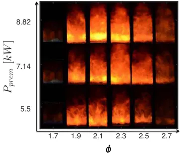
FIGURE 5: Evolution of flame luminosity with Ppremand equiv-alence ratio for Tc= 573 K.
a.
ϕ
b.FIGURE 6: Effect of equivalence ratio on: a) flame luminosity and b) soot volume fraction fvfor Pprem= 7.14 kW and Tc= 573 K.
Ptot≈7 kW) is performed before each experiment until the target temperature is reached. In the following experiments, this tem-perature was fixed at Tc= 573 K, assuring a sufficient soot pro-duction for LII detection, a good repeatability and a quasi-steady state for the thermal environment. Due to this temperature vari-ation and other experimental uncertainties, a variability of 15 % on soot volume fraction results has been observed.
EFFECTS OF EQUIVALENCE RATIO AND FLAME POWER
FIGURE 7: Evolution of the signal detected with the ASAHI filter for different equivalence ratios with an exposure time of 5 µs. The stabilization of a flame was not possible with this design injector for 0.7 < φ < 1.3 due to flashbacks. Data are not shown for 1.7 < φ < 2.4 due to signal saturation of the detector.
One interesting feature of a premixed flame configuration is that the effects of the operating conditions on soot production can
be more easily identified than in a non-premixed situation, where any parameter may lead to a modification of the mixing process subsequently affecting soot production. Here, the equivalence ratio φ and Ppremhave been changed and their effects on soot production can be easily identified in Fig. 5. In particular, the effect of the equivalence ratio φ is shown in Fig. 6a.
The first visible orange soot streaks appear at around φ= 1.6 with a blue region below. This region disappears when the equiv-alence ratio exceeds φ = 1.7. This feature is confirmed in an indirect manner by examining the signal delivered by a Photron SAX coupled with an Hamamatsu intensifier with a UV objec-tive (GW= 5 µs) and equipped with an ASAHI bandpass filter (ZBPA310). This filter separates the OH∗
chemiluminescence signal from the background radiation. However this filter has sidebands and one of them is located in the 800-1200 nm and the transmissivity in that range is of 0.01%.
The signal level displayed in Fig. 7 corresponds to a wide range of equivalence ratios. As expected [30], the OH∗
chemilu-minescence signal increases in the lean region between φ = 0.4 and φ = 0.7 and decreases between φ = 1.3 and φ = 1.5. The vicinity of the stoichiometric value could not be reached because of flashback. The signal detected by the camera starts to rise again for φ > 1.5. This is not due to the OH∗
chemilumines-cence but to the radiation of soot particles that is strong enough to compensate the low filter transmissivity in the band 800-1200 nm [5, 6]. One may deduce from this observation that the first soot particles appear at φ ≈ 1.6, close to the value determined in lam-inar premixed flames [5,6]. The soot emission becomes so domi-nant that it is not possible to obtain with the current setup images of OH∗
chemiluminescence field of the flame for equivalence ra-tios corresponding to the range where soot is present. However, by considering the OH∗
field from a lean flame (φ= 0.66) in Fig. 8a and from a non sooting rich flame (φ= 1.48) in Fig. 8b, one can conclude that the OH∗
signal is essentially localized close to the combustor backplane plane, indicating that the swirled flame
OH* (UA) -4 -2 0 2 4 r [cm] 12 10 8 6 4 2 0 HAB [cm] 0 500 1000 1500 2000 2500 3000 3500 a. OH* (UA) -4 -2 0 2 4 r [cm] 12 10 8 6 4 2 0 HAB [cm] 0 500 1000 1500 2000 2500 3000 3500 b. FIGURE 8: Integrated OH∗
field for a) φ= 0.66 and b) φ = 1.48.
expands in the lateral direction. This peculiar flame structure has already been observed for perfectly premixed lean swirled flames [31] in a similar burner and depends on the injector de-sign. By assuming that the flame structure will keep a similar shape at higher equivalence ratios, one may consider that the re-action zone for the sooting flames examined in this article is es-tablished near the combustor backplane. This is also confirmed by the presence of a blue flame in this region for φ = 1.6 − 1.7 (Fig. 6).
Concerning LII measurements (Fig 6b), the soot volume fraction is only detectable when the equivalence ratio exceeds φ= 1.7, a value that is probably linked to the detection limit of the optical setup ( fmin
v = 10 ppb). The soot volume fraction in-creases with φ reaching a maximum at φ= 2.1. It then decreases after this critical value until the rich extinction limit φ= 2.8. It is found that φ= 2.1 is the equivalence ratio leading to a maxi-mum of soot production for all the power levels considered in this investigation. Since the power is proportional to the Reynolds number one finds that the maximum soot volume fraction is ob-tained at a fixed value of the equivalence ratio for a wide range of Reynolds numbers. However this critical equivalence ratio is suspected to be strongly dependent on the burner design.
Concerning flame power, soot luminosity and total soot vol-ume fraction increase with Pprem, as observed in Fig 9. However, after an initial quick growth, the soot volume fraction production seems to reach a “plateau” at higher power levels.
4.76 kW 7.14 kW 9.52 kW 11.9 kW 14.28 kW a. b.
FIGURE 9: Effect of Ppremon: a) flame luminosity and b) soot volume fraction fvfor φ= 2.1 and Tc= 573 K.
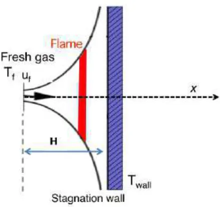
FIGURE 10: Schematic of the burner-stabilized stagnation flame.
RICH PREMIXED STRAINED FLAME MODELING
To obtain some understanding of the observed effects of wall temperature and equivalence ratio, it is natural to exam-ine an idealized configuration that is classically considered in literature to investigate soot production under premixed condi-tions [32–35]. It consists of a rich premixed strained laminar sooting flame formed in the vicinity of a stagnation plate with a given temperature, as schematically represented in Fig. 10. This rich premixed strained flame may be obtained experimen-tally by placing a nozzle injecting fresh premixed reactants in the vicinity of a plane thus forming a flat flame near the plane. This configuration is usually designated as a burner-stabilized stagnation (BSS) flame [32]. In this work, a premixed ethy-lene/air fresh mixture, corresponding to the ambient temperature Tf = 293 K, is stabilized against a stagnation plate at tempera-ture Twallat distance H= 6 mm. The plate temperature and the equivalence ratio are varied to reproduce the experimental oper-ating conditions. The injection velocity uf is chosen to impose a strain rate a= H/uf ≈15 s−1. Considering a self-similarity approximation in the vicinity of the jet central-axis, simulations are performed using the REGATH solver for 0-D and 1-D cal-culations [36]. The detailed KM2 mechanism (202 species with 1351 reactions) [37], describing the gas phase, is coupled with the sectional method developed in [38], where it has been vali-dated on experimental sooting BSS flames [32,35]. All details on the gas and solid phase models can be found in [38]. This config-uration is of course not representative of the turbulent premixed flame investigated in this article but, as already said, it serves to study the role of the wall temperature and of the equivalence ratio on soot production.
Effect of wall temperature
It was observed that the total soot volume fraction increases with the wall temperature in the EM2Soot burner. Many rea-sons can be proposed to explain these trends. Among them, one
a. b.
c. d.
e. f.
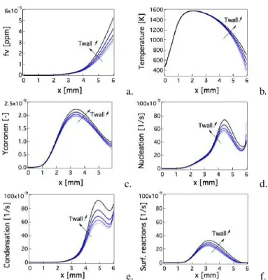
FIGURE 11: Numerical flame structure along the jet central axis for a BSS premixed flame. Five wall temperatures (Twall= 300, 400, 500, 600, 700 K) have been considered.
may exclude any retro-coupling of soot with respect to the tem-perature field inside the chamber, since for the small levels of fvdetected in this configuration, the soot radiation contribution are expected to be negligible with respect to the gaseous radia-tion [39]. Therefore, a direct effect of wall temperature on the gaseous quantities affecting soot production is the most prob-able phenomenon. To examine this point and obtain a deeper understanding of the observed trend, it is interesting to consider numerical simulations of soot in the BSS configuration for dif-ferent values of Twall.
Numerical results of soot volume fraction are displayed in Fig. 11a for five wall temperatures and confirm the observed ten-dency. It is found that the profiles of C2H2 and OH species, mainly responsible for soot surface reactions, are not modified by the value of Twall (not shown). In contrast, the profile of coronene in Fig. 11c, representative of soot precursors respon-sible for soot nucleation and condensation phenomena, is cor-related to the temperature profiles shown in Fig. 11b. Along the flame, the concentration of the polycyclic aromatic hydro-carbons (PAHs), such as coronene, increases with temperature. At x= 3 mm, the temperature starts to decrease due to the ef-fect of the wall temperature, reducing PAH production, which requires high temperature values. The smallest the wall tem-perature, the quickest gas temperature and, consequently, PAH
concentration decrease. Therefore, by increasing the wall tem-perature, a higher concentration of soot precursors is obtained enhancing nucleation and condensation processes as illustrated in Figs. 11d and 11e. In turn, this yields soot particles that are characterized by larger volume and surface area, consequently increasing the contribution of surface reactions (Fig. 11f). This finally leads to a higher final soot volume fraction.
In view of the behavior observed on the BSS configuration, one can deduce that the strong response of soot production to the thermal environment in the EM2soot configuration is probably governed by the production of polycyclic aromatic hydrocarbon, which is expected to increase with Tc.
Effect of the equivalence ratio
In order to characterize the effect of the equivalence ratio, numerical simulations of the BSS configuration have been per-formed for five equivalence ratio φ = 1.9, 2.1, 2.3, 2.5, 2.7. Re-sults for the soot volume fraction are displayed in Fig. 12 and show that soot production increases with the equivalence ra-tio for all values considered. This tendency is in agreement with what has been observed in experiments on laminar pre-mixed flames [40], but is in contrast with what is observed in the EM2Soot flame for which a critical equivalence ratio (φ= 2.1), corresponding to the maximum of soot production, has been de-tected. This might indicates that variations in soot production in a swirled premixed rich flames as a function of the equivalence ratio, especially for extremely high equivalence ratios, are con-trolled by interactions between the flame, turbulent eddies and soot production that are obviously not observed in laminar cases. Therefore, the characterization of this phenomenon cannot be ex-plained by knowledge on laminar sooting flames and requires ad-ditional experimental and numerical investigations on turbulent flames.
FIGURE 12: Numerical results for a BSS premixed flame. Five equivalence ratio (φ = 1.9, 2.1, 2.3, 2.5, 2.7) have been consid-ered.
CONCLUSIONS
A model scale combustor enabling the study of perfectly premixed ethylene/air rich swirled flames has been developed to study soot production mechanisms. Experiments carried out in this setup demonstrate the feasibility of quantitative measure-ments of soot volume fraction in stabilized rich sooting premixed flames in a confined environment. Soot production was studied quantitatively with LII for different equivalence ratios, flow rates and thermal conditions. These experiments highlight two critical equivalence ratios, the first (φ = 1.6) is the minimum equiva-lence ratio to detect soot particles while the second (φ= 2.1) is the optimum equivalence ratio for soot production. These values are suspected to be dependent on the turbulence-flame-soot-heat transfer coupling, i.e. on the burner design. Wall temperatures are found to play an important role on soot production in the present configuration. It is found that the soot volume fraction is increased as the wall temperature is augmented. This phe-nomenon is apparently linked to the PAH production that is en-hanced by the presence of a heated wall. This behavior is con-firmed by BSS calculations of rich premixed flames formed in the vicinity of a stagnation plane. The use of BSS calculations constitutes a promising tool in the analysis of the basis physics taking place in this configuration. However, it does not replace a more complete simulation of the turbulent sooting flame that will have to take into account more complex interactions between soot, flame, turbulence and wall thermal conditions.
ACKNOWLEDGMENT
Support from G.Legros and J.Bonnety (UPMC) for the LII calibration through the MAE technique is gratefully acknowl-edged. This study is supported by the Air Liquide, CentraleSup-elec and CNRS Chair on oxycombustion and heat transfer for en-ergy and environment and by the OXYTEC project, grant ANR-12-CHIN-0001 of the French Agence Nationale de la Recherche.
REFERENCES
[1] Seinfeld, J. H., 1998. “Clouds, contrails and climate”. Na-ture, 391(6670), pp. 837–838.
[2] Seaton, A., Tran, L., Aitken, R., and Donaldson, K., 2009. “Nanoparticles, human health hazard and regulation”. J. R. Soc. Interface, pp. 119–129.
[3] Smooke, M., Long, M., Connelly, B., Colket, M., and Hall, R., 2005. “Soot formation in laminar diffusion flames”. Combust. Flame, 143(4), pp. 613–628.
[4] Kempema, N. J., and Long, M. B., 2016. “Boundary condi-tion thermometry using a thermographic-phosphor-coated thin filament”. Appl. Opt., 55(17), pp. 4691–4698. [5] Bladh, H., Olofsson, N.-E., Mouton, T., Simonsson, J.,
Mercier, X., Faccinetto, A., Bengtsson, P.-E., and Des-groux, P., 2015. “Probing the smallest soot particles in
low-sooting premixed flames using laser-induced incandes-cence”. Proc. Combust. Inst., 35(2), pp. 1843–1850. [6] Betrancourt, C., Liu, F., Desgroux, P., Mercier, X.,
Fac-cinetto, A., Salamanca, M., Ruwe, L., Kohse-Hinghaus, K., Emmrich, D., Beyer, A., Glzhuser, A., and Tritscher, T., 2017. “Investigation of the size of the incandescent incipi-ent soot particles in premixed sooting and nucleation flames of n-butane using LII, HIM, and 1 nm-SMPS”. Aerosol Sci. Technol., 51(8), pp. 916–935.
[7] Santoianni, D. A., Decroex, M. E., and Roberts, W. L., 2001. “Temperature Imaging in an Unsteady Propane-Air Counterflow Diffusion Flame Subjected to Low Frequency Oscillations”. Flow Turbul. Combust., 66(1), pp. 23–36. [8] Hamins, A., Yang, J. C., and Kashiwagi, T., 1992. “An
experimental investigation of the pulsation frequency of flames”. Symposium (International) on Combustion, 24(1), pp. 1695–1702.
[9] Oliveira, F. L. d., Barreta, L. G., and Lacava, P. T., 2009. “Experimental aspects of soot presence in pulsating diffu-sion flame”. J. Braz. Soc. Mech. Sci. Eng., 31(2), pp. 137– 141.
[10] Aleksandrov, A., and Bockhorn, H., 2015. “Experimen-tal Investigation of the impact of imposed air inlet velocity oscillations on Soot Formation and Oxidation using an ad-vanced 2-Colour-TIRE-LII”. Appl. Phys. B, pp. 1–6. [11] Decroix, M., and Roberts, W., 2000. “Transient Flow Field
Effects on Soot Volume Fraction in Diffusion Flames”. Combust. Sci. Technol., 160(1), pp. 165–189.
[12] Hentschel, J., Suntz, R., and Bockhorn, H., 2005. “Soot for-mation and oxidation in oscillating methane-air diffusion flames at elevated pressure.”. Appl. Opt., 44(31), pp. 6673– 6681.
[13] Dworkin, S. B., Connelly, B. C., Schaffer, A. M., Bennett, B. a. V., Long, M. B., Smooke, M. D., Puccio, M. P., McAn-drews, B., and Miller, J. H., 2007. “Computational and experimental study of a forced, time-dependent, methane-air coflow diffusion flame”. Proc. Combust. Inst., 31 I, pp. 971–978.
[14] Connelly, B. C., 2009. “Quantitative characterization of steady and time-varying, sooting, laminar diffusion flames using optical techniques”. PhD thesis, Yale University. [15] Lee, S. Y., Turns, S. R., and Santoro, R. J., 2009.
“Measure-ments of soot, OH, PAH concentrations in turbulent ethy-lene/air jet flames”. Combust. Flame, 156(12), pp. 2264– 2275.
[16] Franzelli, B., Scouflaire, P., and Candel, S., 2015. “Time-resolved spatial patterns and interactions of soot, PAH and OH in a turbulent diffusion flame”. Proc. Combust. Inst., 35(2), pp. 1921–1929.
[17] Geigle, K. P., Zerbs, J., K¨ohler, M., St¨ohr, M., and Meier, W., 2011. “Experimental analysis of soot formation and ox-idation in a gas turbine model combustor using laser
diag-nostics”. J. Eng. Gas Turbines Power, 133(12), p. 121503. [18] Geigle, K. P., K¨ohler, M., OLoughlin, W., and Meier, W., 2015. “Investigation of soot formation in pressurized swirl flames by laser measurements of temperature, flame struc-tures and soot concentrations”. Proc. Combust.Inst., 35(3), pp. 3373–3380.
[19] El-Asrag, H., Lu, T., Law, C., and Menon, S., 2007. “Sim-ulation of soot formation in turbulent premixed flames”. Combust. Flame, 150(1), pp. 108 – 126.
[20] Desgroux, P., Mercier, X., and Thomson, K. A., 2013. “Study of the formation of soot and its precursors in flames using optical diagnostics”. Proc. Combust. Inst., 34(1), pp. 1713 – 1738.
[21] Shaddix, C. R., and Smyth, K. C., 1996. “Laser-induced incandescence measurements of soot production in steady and flickering methane, propane, and ethylene diffusion flames”. Combust.Flame, 107(4), pp. 418 – 452.
[22] Melton, L. A., 1984. “Soot diagnostics based on laser heat-ing”. Appl. Opt., 23(13), pp. 2201–2208.
[23] Franzelli, B., Roussillo, M., Scouflaire, P., Bonnety, J., Alain, J., Candel, S., and Legros, S., 2018. “Multi-diagnostic soot measurements in a laminar diffusion flame to assess the ISF database consistency”. Proc. Combust. Inst., submitted.
[24] Roussillo, M., Scouflaire, P., Bonnety, J., Legros, G., Can-del, S., and Franzelli, B., 2017. “Improving the reliability of the ISF experimental database on pulsed sooting laminar diffusion flames: Soot volume fraction measurements using MAE and LII techniques”. European Combustion Meeting, Dubrovnik, April.
[25] Mouton, T., 2014. “Particules de suie dans des flammes par fluorescence induite par laser en jet froid applique aux hydrocarbures aromatiques”. PhD thesis, PC2A.
[26] Legros, G., Wang, Q., Bonnety, J., Kashif, M., Morin, C., Consalvi, J.-L., and Liu, F., 2015. “Simultaneous soot temperature and volume fraction measurements in axis-symmetric flames by a two-dimensional modulated ab-sorption/emission technique”. Combust. Flame, 162(6), pp. 2705–2719.
[27] Michelsen, H., Liu, F., Kock, B., Bladh, H., Boiarciuc, A., Charwath, M., Dreier, T., Hadef, R., Hofmann, M., Reimann, J., Will, S., Bengtsson, P.-E., Bockhorn, H., Foucher, F., Geigle, K.-P., Mouna¨ım-Rousselle, C., Schulz, C., Stirn, R., Tribalet, B., and Suntz, R., 2007. “Modeling laser-induced incandescence of soot: a summary and com-parison of LII models”. Appl. Phys. B, 87(3), pp. 503–521. [28] Crosland, B. M., Thomson, K. A., and Johnson, M. R., 2013. “Instantaneous in-flame measurement of soot volume fraction, primary particle diameter, and aggregate radius of gyration via auto-compensating laser-induced incandes-cence and two-angle elastic light scattering”. Appl. Phys. B, 112(3), Sep, pp. 381–393.
[29] Saito, M., Iwabuchi, H., and Murata, I., 2016. “Estimation of spectral distribution of sky radiance using a commercial digital camera”. Appl. Opt., 55(2), pp. 415–424.
[30] Panoutsos, C., Hardalupas, Y., and Taylor, A., 2009. “Nu-merical evaluation of equivalence ratio measurement us-ing OH and CH chemiluminescence in premixed and non-premixed methane–air flames”. Combust. Flame, 156(2), pp. 273–291.
[31] Jourdaine, P., Mirat, C., Beaunier, J., Caudal, J., Joumani, Y., and Schuller, T., 2016. “Effect of quarl on N2-and CO2-diluted methane oxy-flames stabilized by an axial-plus-tangential swirler”. In ASME Turbo Expo 2016: Tur-bomachinery Technical Conference and Exposition. [32] Abid, A. D., Camacho, J., Sheen, D. A., and Wang, H.,
2009. “Quantitative measurement of soot particle size dis-tribution in premixed flames–the burner-stabilized stagna-tion flame approach”. Combust. Flame, 156(10), pp. 1862– 1870.
[33] Camacho, J., Lieb, S., and Wang, H., 2013. “Evolution of size distribution of nascent soot in n-and i-butanol flames”. Proc. Combust. Inst., 34(1), pp. 1853–1860.
[34] Lindstedt, R., and Waldheim, B., 2013. “Modeling of soot particle size distributions in premixed stagnation flow flames”. Proc. Combust. Inst., 34(1), pp. 1861–1868. [35] Camacho, J., Liu, C., Gu, C., Lin, H., Huang, Z., Tang, Q.,
You, X., Saggese, C., Li, Y., Jung, H., et al., 2015. “Mo-bility size and mass of nascent soot particles in a bench-mark premixed ethylene flame”. Combust. Flame, 162(10), pp. 3810–3822.
[36] Darabiha, N., 1992. “Transient behaviour of laminar coun-terflow hydrogen-air diffusion flames with complex chem-istry”. Combust. Sci. Technol., 86(1-6), pp. 163–181. [37] Wang, Y., Raj, A., and Chung, S. H., 2013. “A PAH
growth mechanism and synergistic effect on PAH formation in counterflow diffusion flames”. Combust. Flame, 160(9), pp. 1667–1676.
[38] Rodrigues, P., Franzelli, B., Vicquelin, R., Gicquel, O., and Darabiha, N., 2017. “Unsteady dynamics of PAH and soot particles in laminar counterflow diffusion flames”. Proc. Combust. Inst, 36(1), pp. 927–934.
[39] Rodrigues, P., 2018. “Coupled large eddy simulations of sooting turbulent flames”. PhD thesis, CentraleSupelec. [40] Melton, T. R., Inal, F., and Senkan, S. M., 2000. “The
effects of equivalence ratio on the formation of poly-cyclic aromatic hydrocarbons and soot in premixed ethane flames”. Combust. Flame, 121(4), pp. 671 – 678.