HAL Id: tel-00806245
https://pastel.archives-ouvertes.fr/tel-00806245
Submitted on 29 Mar 2013HAL is a multi-disciplinary open access archive for the deposit and dissemination of sci-entific research documents, whether they are pub-lished or not. The documents may come from teaching and research institutions in France or abroad, or from public or private research centers.
L’archive ouverte pluridisciplinaire HAL, est destinée au dépôt et à la diffusion de documents scientifiques de niveau recherche, publiés ou non, émanant des établissements d’enseignement et de recherche français ou étrangers, des laboratoires publics ou privés.
Lourdes Patricia Ramirez
To cite this version:
Lourdes Patricia Ramirez. Few-cycle OPCPA laser chain. Other [cond-mat.other]. Université Paris Sud - Paris XI, 2013. English. �NNT : 2013PA112012�. �tel-00806245�
Logo de l’établissement co-tutelle éventuellement)
UNIVERSITE PARIS-SUD
ÉCOLE DOCTORALE : EDOM
Laboratoire Charles Fabry DISCIPLINE PHYSIQUE
THÈSE DE DOCTORAT
soutenue le 29/01/2013
par
Lourdes Patricia RAMIREZ
Few-cycle OPCPA laser chain
Composition du jury :
Président du jury : M. Fabien BRETENAKER Rapporteurs : Mme Béatrice CHATEL
M. Manuel JOFFRE Examinateurs : M. Eric CORMIER
Mme Aurélie JULLIEN M. Dimitris PAPADOPOULOS
The Apollon-10 PW laser chain is a large-scale project aimed at delivering 10 PW pulses to reach intensities of 1022 W/cm2. State of the art, high intensity lasers based solely on chirped pulse amplification (CPA) and titanium sapphire (Ti:Sa) crystals are limited to peak powers reaching 1.3 PW with 30-fs pulses as a result of gain narrowing in the amplifiers. To access the multipetawatt regime, gain narrowing can be suppressed with an alternative amplification technique called optical parametric chirped pulse amplification (OPCPA), offering a broader gain bandwidth and pulse durations as short as 10 fs. The Apollon-10 PW laser will exploit a hybrid OPCPA-Ti:Sa-CPA strategy to attain 10-PW pulses with 150 J and 15 fs. It will have two high-gain, moderate-energy amplification stages (10 fs, 100 mJ range) based on OPCPA in the picosecond and nanosecond timescale and afterwards, will use Ti:Sa for power amplification to the 100-Joule level.
Work in this thesis involves the progression of the development on the Apollon-10 PW front end and is focused on the development of a high contrast, ultrashort seed source supporting 10-fs pulses, stretching these pulses prior to OPCPA and the implementation of the picosecond OPCPA stage with a target of achieving 10-mJ pulses and maintaining its bandwidth. To achieve the final goal of 15-fs, 150-J pulses, the seed source must have a bandwidth supporting 10-fs and a temporal contrast of at least 1010. Thus from an initial commercial Ti:Sa source delivering 25-fs pulses with a contrast of 108, spectral broadening via self-phase modulation and contrast enhancement with cross polarized (XPW) generation was performed. Subsequently, the seed pulses were stretched to a few picoseconds to match the pump for picosecond OPCPA. Stretcher designs including an acousto-optic programmable dispersive filter (Dazzler) for the purpose of phase control were studied. The final stretcher configuration using BK7 glass was compact and straightforward and an associated compressor for pulse monitoring was also tested. Lastly, the picosecond OPCPA stage was implemented in single and dual stage configurations.
I would like to express my gratitude to my advisers, Frédéric Druon and Dimitris Papadopoulos. First for accepting and trusting me to work on such a big project and second for mentoring me over the past three years. I would like to thank Frédéric for sharing his insights on the scientific process, patience during my manuscript writing and constant encouragement. I am grateful for having the opportunity to work closely with Dimitris, who taught me so many things, always had innovative and bright ideas and added laughter to our experiments.
The front end team would not be complete without the leadership of Patrick Georges and master engineering skills of Alain Pellegrina. I am indebted to Patrick for advising me not only in terms of research but for his concern and help with matters regarding the bureaucracy I had to navigate throughout my PhD. Alain’s competence in managing our complex laser system and his elegant design of our setups made the implementation of our experiments a little bit easier. He was also always available to offer me a helping hand.
The results in this thesis were obtained under many collaborative efforts. I would like to thank the members of the Physique du Cycle Optique group of LOA, namely, Aurélie Jullien, Aurélien Ricci, Xiaowei Chen, Jean-Philippe Rousseau and Rodrigo Lopez-Martens, who shared their expertise on hollow fiber compression and cross polarized wave generation and also for lending me a lot of things from their lab. Our contrast measurements were taken with the help of Pascal Monot from IRAMIS of CEA. With issues regarding our Dazzler, I was very fortunate to receive the assistance of Nicolas Forget and Thomas Oksenhendler of Fastlite. Nicolas also contributed in designing a grism stretcher while Thomas helped us measure our compressed pulses with a Wizzler device. I would also like to thank Marc Hanna of the Groupe Laser for helping me with my simulations on XPW.
The culmination point of my work was this manuscript and my defense. I would like to acknowledge my rapporteurs, Béatrice Chatel and Manuel Joffre for reviewing my manuscript and my jury members, Fabien Bretenaker, Eric Cormier and Aurélie Jullien for participating in my defense. I am thankful for their ideas, comments and questions which have helped me in improving the manuscript.
I am especially grateful to the members of the Groupe Laser for extending their friendship and help since I started, and their heartfelt encouragement towards the days before my defense. I would also like to thank Ivy and Antonio Colambo for welcoming me into their family and for
insightful advice to help me keep going.
Lastly, I would like to thank my family. In France, I was able to share all my ups and downs throughout my PhD with my best friend, Liye Shan. We kept each other sane and drove each other insane but she was there for me during the hardest times. Most importantly, I would like to thank my family in the Philippines who have always offered their unconditional support despite the distance and have continuously prayed for my success in this endeavor.
ABSTRACT ... i
!
ACKNOWLEDGMENTS ... iii
!
CHAPTER 1:INTRODUCTION ... 1
!
1.1. Ultrahigh peak powers and intensities ... 1
!
1.1.1. Laser development ... 1
!
1.1.2. Light-matter interaction at ultrahigh intensities ... 2
!
1.1.3. Challenges in the multipetawatt regime ... 5
!
1.2. Optical parametric chirped pulse amplification ... 5
!
1.2.1. Advantages and disadvantages ... 6
!
1.2.2. OPCPA based petawatt laser systems ... 7
!
1.3. Framework of the Apollon-10 PW laser ... 9
!
1.3.1. System description ... 9
!
1.3.2. Front end architecture ... 10
!
1.4. Framework of this thesis ... 11
!
CHAPTER 2:THE APOLLON 10-PWFRONT END ... 13
!
2.1. The Apollon-10 PW Front End sub-systems: A Fast Overview ... 13
!
2.1.1. Ultrashort seed source ... 14
!
2.1.2. Picosecond pump and OPCPA stage ... 15
!
2.1.3. Nanosecond pump, stretcher and OPCPA stage ... 16
!
2.2. The ultrashort seed source ... 18
!
2.2.1. Ultrabroadband Ti:Sa oscillator: Femtosource Rainbow ... 18
!
2.2.2. Multipass Ti:Sa amplifier: Femtopower ... 19
!
2.2.3. CEP and stabilization ... 21
!
2.3. The picosecond OPCPA pump ... 23
!
2.3.1. Ytterbium Doped Fiber Amplifier ... 23
!
2.3.2. Stretcher and S-Pulse amplifier ... 25
!
2.3.3. MBI amplifier ... 25
!
2.3.4. Compression and frequency doubling ... 26
!
2.4. Seed and pump pulse synchronization ... 27
!
2.5. The nanosecond OPCPA pump and stretcher ... 29
!
2.5.1. Multipass amplifier 1 ... 29
!
2.5.2. Öffner stretcher ... 30
!
2.6. Progression in the development of the Front End ... 31
!
CHAPTER 3:DEVELOPMENT OF AN ULTRASHORT SEED SOURCE ... 33
!
3.1. Requirements of the seed source ... 33
!
3.1.1. Pulse duration ... 33
!
3.1.2. Contrast ... 35
!
3.1.3. CEP preservation ... 37
!
3.2. Hollow fiber pulse compression ... 37
!
3.2.1. Spectral broadening via self-phase modulation ... 38
!
3.2.2. Dispersion and self-steepening ... 40
!
3.2.3. Propagation in a hollow fiber ... 40
!
3.2.4. Compression with chirped mirrors ... 43
!
3.3. Cross polarized wave generation for contrast enhancement and pulse compression ... 44
!
3.3.1. Theory of cross polarized wave generation ... 46
!
3.3.2. Pulse compression ... 48
!
3.4. 5-fs seed source: ultrashort XPW ... 50
!
3.4.1. Generation and characterization of 5-fs pulses ... 51
!
3.4.5. Contrast measurement ... 60
!
3.4.6. CEP stabilization ... 62
!
3.5. 10-fs seed source: energy efficient XPW for pulse compression ... 63
!
3.5.1. Hollow waveguide setup ... 64
!
3.5.2. Efficiency and spectral phase dependence ... 65
!
3.5.3. Pulse compression via XPW ... 67
!
3.5.4. CEP stabilization ... 68
!
3.5.5. Energy scalability ... 69
!
3.5.6. Contrast measurement ... 70
!
3.6. Two-crystal XPW: 10-fs pulses with lower intensities ... 72
!
3.6.1. Two-crystal XPW simulations: First crystal ... 73
!
3.6.2. Two-crystal XPW simulations: Global system ... 76
!
3.6.3. Experimental results ... 79
!
3.7. Summary ... 81
!
CHAPTER 4:SEED STRETCHER DESIGN FOR PICOSECOND OPCPA ... 85
!
4.1. Impact of seed and pump temporal durations on OPCPA ... 85
!
4.2. Dispersion ... 86
!
4.3. Dispersion management ... 88!
4.3.1. Material dispersion ... 89!
4.3.2. Grating pair ... 90!
4.3.3. Prism pair ... 91!
4.3.4. Grisms ... 92!
4.3.5. High dispersion mirrors ... 93
!
4.3.6. Dazzler ... 94
!
4.4. Negative stretching ... 96!
4.4.1. Grating configurations ... 97!
4.4.2. Prism configurations ... 99!
4.4.3. Grisms ... 102!
4.5. Positive stretching ... 103!
4.6. Final seed configuration ... 105
!
4.7. Summary ... 106
!
CHAPTER 5:OPTICAL PARAMETRIC CHIRPED PULSE AMPLIFICATION ... 109
!
5.1. Theory of optical parametric amplification ... 109
!
5.1.1. Coupled-wave equations ... 110
!
5.1.2. Analytical solutions and parametric gain ... 111
!
5.1.3. Phase evolution equations ... 115
!
5.1.4. Phase matching for ultrabroadband pulses ... 116
!
5.1.5. Amplified parametric superfluorescence ... 121
!
5.1.6. Contrast enhancement ... 123
!
5.2. Numerical simulation of OPCPA ... 124
!
5.2.1. Signal dependence on pump intensity ... 126
!
5.2.2. Pulse duration and conversion efficiency ... 127
!
5.2.3. Energy instabilities of the pump and signal ... 128
!
5.2.4. Preservation of CEP ... 128
!
5.2.5. Pump-seed synchronization and temporal jitter ... 129
!
5.2.6. Efficiency dependence on spatial profiles ... 131
!
5.2.7. Design of the OPCPA stage for Apollon-10 PW ... 133
!
5.3. Single stage OPCPA: Experimental implementation ... 135
!
5.3.1. Experimental setup and alignment of the amplifier ... 135
!
5.3.2. Pump energy dependence ... 136
!
5.3.3. Seed energy dependence ... 138
!
5.4.2. First stage: pump energy dependence ... 140
!
5.4.3. Compression with high dispersion mirrors ... 143
!
5.4.4. Second stage: pump energy dependence ... 146
!
5.4.5. Issues with the pump beam ... 148
!
5.4.6. Temporal instabilities ... 148
!
5.5. Summary ... 150
!
CHAPTER 6:CONCLUSIONS AND PERSPECTIVES ... 153
!
APPENDIX A:ULTRASHORT PULSE CHARACTERIZATION ... 157
!
A.1. Pulse characterization: Single-shot few-cycle FROG ... 157
!
A.2. Pulse characterization: Wizzler ... 159
!
A.3. Carrier envelope phase stability: f-to-2f interferometer ... 160
!
A.4. Contrast measurement: Third order cross-correlator ... 161
!
APPENDIX B:DISPERSION CALCULATIONS ... 163
!
B.1. Sellmeier equations ... 163
!
B.1.1. Glasses ... 163
!
B.1.2. Crystals ... 163
!
B.2. Dispersion of grating configurations ... 164
!
B.3. Dispersion of prism configurations ... 165
!
APPENDIX C:JACOBI ELLIPTIC FUNCTIONS ... 167
!
I
NTRODUCTIONUltrashort laser pulses are the shortest events created. The idea of how amazingly short an ultrashort laser pulse is, is often illustrated by the following analogy: a 10 fs pulse (10-15 s) is to 1 minute as 1 minute is to the age of the universe [Tre 12]. Confinement of even a small amount of energy within these short time spans leads to extremely high peak powers. Typical turn-key systems deliver peak powers in the order of mega to gigawatts (106-109 W) which in terms of electrical power, is equivalent to the amount of power consumption of a Boeing 747 airplane (140 MW) to the power generated by the Hoover Dam (2 GW) in the United States and the peak electrical power consumption of France (101.6 GW) [Wik 12]. With the maturity of the available laser technologies, these pulses are routinely produced not only in research laboratories but in medical and industrial settings as well. Their applications range from taking ultrashort snapshots of fast-evolving chemical reactions at the atomic scale [Zew 88] to utilizing their high peak powers for performing delicate tasks such as injecting genes into cells [Tir 02] and eye surgery [Rat 01, Mor 09], which has already been commercialized [Opt 12]. Further industrial integration of ultrashort pulses is promising in the area of materials processing where ablation at a shorter time scale occurs and reduces thermal damage to have precise and high quality micromachining [Anc 08].
1.1.ULTRAHIGH PEAK POWERS AND INTENSITIES
1.1.1.LASER DEVELOPMENT
Research in ultrafast laser development has been driven by the goal of achieving more powerful pulses by means of (1) decreasing the pulse duration and (2) increasing the pulse energy. Within 20 years, shorter pulses were obtained with the improvement of mode-locking techniques and the availability of broader bandwidth gain media. The first ultrashort lasers were based on fluorescent dyes due to their broad emission spectra [Ipp 74]. Interest in solid state media emerged afterwards and led to the discovery of the titanium-doped sapphire crystal (Ti:Sa)—the material of choice for ultrashort lasers [Mou 88] because of its excellent thermal properties and exceptionally broad gain bandwidth. Another milestone in the development of ultrafast lasers was the discovery of Kerr-Lens Mode-locking (KLM) in Ti:Sa. In this technique, self-focusing in the gain medium provides a fast self-amplitude modulation for mode-locking the pulses [Spe 91]. Together with chirped mirrors for intra-cavity dispersion management, the combination of KLM and Ti:Sa was established to produce sub-10 fs pulses [Sti 95]. These innovations resulted to turn-key systems generating pulses as short as 5 fs and peak powers reaching the gigawatt level.
Figure 1.1.1. Concept of chirped pulse amplification [Str 85]. An ultrashort seed pulse is temporally
stretched prior to amplification to prevent damage to the laser amplifier due to high peak powers and intensities. After amplification, the pulse is recompressed to its original pulse duration when the dispersion of the stretcher, laser amplifier material and compressor are matched. Image is courtesy of [Jov 10].
Increasing the energy of these pulses can be implemented via amplification. However, as a consequence of their durations, the pulses have intensities in the ~109 W/cm2 range where self-focusing can create filaments and cause irreversible optical damage in the system. Initially, decreasing the intensity with a larger beam size was one way to work around the problem but led to bigger optics, higher costs and lower repetition rates [Bib 92]. Chirped pulse amplification (CPA) [Str 85] is a more elegant solution for amplifying ultrashort pulses. Instead of expanding the beam spatially, the idea behind CPA, which is shown in Figure 1.1.1, is to have lower intensities before amplification by stretching the pulse temporally with dispersive elements such as gratings. Pulses are typically stretched to nanosecond temporal durations, thus the intensities are decreased by a factor of 103-105. Energy could then be extracted from the amplifier consisting of a laser gain medium (e.g. Ti:Sa, Nd:Glass, Cr:LiSaF) without worrying about optical damage and beam profile distortions. After amplification, the pulse is recompressed with another pair of gratings close to its initial value, leading to a significant increase in peak power. All laser systems with peak powers greater than 1 TW (1012 W) utilize the CPA principle [Kha 08].
1.1.2.LIGHT-MATTER INTERACTION AT ULTRAHIGH INTENSITIES
CPA was the key technology which gave access to new physical regimes involving superstrong optical fields and matter, as depicted in Figure 1.1.2. Alongside temporal confinement, spatial confinement by focusing the laser pulse onto a target within an area of several square microns creates ultrahigh intensities (>1015 W/cm2) and electric fields comparable to the Coulomb field in atoms. Rapid ionization and plasma formation occurs in gas and solid targets at this intensity level [Kor 11].
!
Figure 1.1.2. Curve depicting the increase in laser intensity through the years and different regimes
accessible with higher intensities.
In the relativistic regime which is characterized by intensities >1018 W/cm2, strong electric fields cause free electrons in the plasma to acquire energies greater than their rest mass (0.511 MeV) and velocities approaching the speed of light [Ums 01]. Laser driven electron acceleration is possible in this regime and is most promising in terms of the development of tabletop accelerators as alternatives to large-scale conventional accelerators which are kilometers in size. Proposed in 1979, an intense laser pulse produces a wake of oscillations in a plasma which accelerates relativistic electrons [Taj 79]. Electron beams with energies as high as 1.3 GeV were accelerated over a length of 3.3 cm [Lee 06] in a laser-plasma-based accelerator.
Figure 1.1.3. Schematic for proton acceleration. A terawatt laser pulse is focused onto the back side of a
thin foil target which creates a plasma that accelerates electrons. The electrons then travel through the foil, ionizing hydrogen and other atoms. The separation of charges creates a strong field which accelerates the protons. This diagram was taken from [Sch 06].
More intense lasers allow the acceleration of even heavier particles—protons and ions, as illustrated in Figure 1.1.3. Tabletop proton sources are particularly interesting because of their medical applications in position emission tomography [Led 04] and proton cancer therapy [Mal 04]. Multi-megaelectron volt (MeV) proton beams are created at intensities >1019 W/cm2 with a thin solid target (~!m). Protons from ionized hydrogen are accelerated to several MeVs by the strong electric field generated by the separation of relativistic electrons and heavier ions [Led03]. At present, the most energetic, 67.5 MeV proton beams were generated with an intensity of 1020 W/cm2 and specially designed target [Gai 11]. Cancer therapy requires protons with energies of 200 MeV to penetrate typical depths of tumors. These energies are believed to be achievable with petawatt class lasers (1015 W) and better targets. Although protons are preferentially accelerated over ions because of their high charge-to-mass ratio, ion acceleration is also possible and has been demonstrated with C, Al and Pb ions [Cla 00, Kru 00].
High harmonic generation also occurs with the interaction of an intense laser pulse and a relativistic plasma evolving from a solid target. Compared to high harmonics from gases or atomic harmonics, the plasma medium permits the usage of higher intensities which induce stronger nonlinearities and results to higher conversion efficiencies [Tsa 06]. Another advantage is that with free electron harmonics, the plateau observed in atomic harmonics is not predicted thus the harmonic order may extend into the kilo-electronvolt part of the spectrum. Additionally, if the laser pulse consists of a few optical cycles, intense attosecond (10-18 s) pulses can also be generated, as seen below.
Figure 1.1.4. Generation of an attosecond pulse train with a few-cycle, high intensity pulse. When laser
intensities reaching ~1018 W/cm2 are incident on a glass target, a plasma is formed which is capable of reflecting the laser pulse. Simultaneously, attosecond light bursts are emitted as a result of coherent wake emission [Tha 07]—a process involving the interaction of the laser with the electrons in the plasma. The image is from [Bor 12].
Intensities at the border of the relativistic and ultrarelativistic regime will be available in the coming years with the development of petawatt class lasers. For intensities around 1022 – 1023 W/cm2, 100 GeV electron beams and 1 GeV proton beams are expected. These intensities are also
!
appealing for experiments in fusion via direct laser acceleration and fast ignitor schemes for inertial confinement [Led 03]. Much progress is needed to reach the ultrarelavistic and nonlinear quantum electrodynamics regime (>1025 W/cm2). Nonetheless, when accomplished, will open doors to more exciting areas of research especially in particle physics and astrophysics. At intensities above 1028 W/cm2, the nucleus can directly be excited and its energy levels altered to shorten decay lifetimes of nuclear waste. Direct electron-positron pair creation in vacuum and the production of Hawking/Unruh (black hole) radiation is predicted to happen at 1029-1030 W/cm2 [Ger 07].
1.1.3.CHALLENGES IN THE MULTIPETAWATT REGIME
CPA systems have been demonstrated to deliver peak powers in excess of 1 PW and intensities around 1021 W/cm2 [Per 99, Dan 04]. Unfortunately, several issues prevent scaling these systems to the multipetawatt level to access higher intensities. Nd:Glass is commonly used as the gain medium for these powerful lasers limiting their pulse durations to around 500 fs because of its narrow spectral bandwidth. Therefore to achieve petawatt power, a lot of energy is required, e.g. 500 J, but the maximum allowable energy is constrained by the damage threshold of the compressor gratings. An alternative approach would be to employ Ti:Sa crystals, well-known to support 30-50 fs pulses at high energies (mJ-level) with their broader gain bandwidth, and with this, higher peak powers with lower energies are possible. However, the main issue of Ti:Sa is its small aperture below 15 cm which may lead to optical breakdown and self-focusing. With the use of laser gain media for amplification, problems such as gain narrowing and amplified spontaneous emission become critical at intensities >1022 W/cm2. Consequently, a new amplification technique is needed to attain multipetawatt peak powers.
1.2.OPTICAL PARAMETRIC CHIRPED PULSE AMPLIFICATION
The limitations in CPA arise mostly from conventional laser amplifiers—bandwidth, gain narrowing and amplified spontaneous emission (ASE). Optical parametric chirped pulse amplification (OPCPA) is a scheme that circumvents these issues by replacing the conventional laser amplifier of CPA with a nonlinear crystal for optical parametric amplification (OPA).
Optical parametric amplifiers have become a widespread source of tunable femtosecond sources and are workhorses of ultrafast spectroscopy [Cer 03]. OPA involves three-wave mixing in a nonlinear crystal wherein a high intensity, high photon energy, pump beam transfers energy to a weak, low photon energy, seed beam resulting to the amplification of the seed. To fulfill the law of energy conservation, another low energy photon, called the idler, is produced. Phase matching conditions must be satisfied between the three waves for conservation of momentum. By introducing a small angle between the pump and seed beams, coined as noncollinear OPA, the
bandwidth of the device spans from the visible to the near infrared [Rie 00] and has been demonstrated to support 4 fs pulses [Bal 02b], a result better than Ti:Sa.
Figure 1.2.1. Schematic diagram for OPCPA. Employing the CPA concept, the seed pulse is stretched prior to amplification and recompressed afterwards. The amplifier consists of the nonlinear crystal and the pump energy is transferred to the chirped seed pulse when both beams satisfy phase matching conditions and are temporally synchronized at the crystal. Image is courtesy of [Jov 10].
High intensity pulses can be generated with OPA when combined with CPA. The idea was investigated in as early as 1986 [Pis 86], just a year after the invention of CPA. The formal combination of OPA and CPA was introduced a few years later [Dub 92] and was subsequently proposed for the construction of petawatt level lasers [Ros 97]. The progress and success of OPCPA is also attributed to the discovery of new nonlinear optical crystals like beta barium borate and lithium borate (BBO, LBO) which possess suitable properties for the amplification of high intensity, ultrabroadband pulses [Xue 00].
1.2.1.ADVANTAGES AND DISADVANTAGES
OPCPA offers many advantages over CPA mainly due to the amplification mechanism of the technique. Most of the disadvantages are related to the pump beam and its temporal synchronization with the signal.
The first and foremost advantage of OPCPA is its gain bandwidth. No laser gain medium can compete with its wide gain bandwidth which can exceed 100 THz, having the potential to amplify sub-10-fs pulses. It is also highly flexible with the geometry of the setup—collinear or noncollinear and several techniques can be employed to improve this bandwidth. Examples of these are pulse front tilt phase matching [Ari 04] and two-color pumping [Herr 10, Har 12]. High peak powers can be accessible with the possibility of supporting very short pulses. Second is the high gain per single pass. The gain of OPA is directly related to the intensity of the pump beam and the length of the crystal [Cer 03] therefore a high gain is expected with intense pump beams. Only several passes are required to obtain the same gain a multipass or regenerative amplifier can produce, removing the need for complex cavities. Also with the decreased passes, less material needs to be compensated for pulse compression and phase accumulation from higher order
!
nonlinear effects is lower. Third is the low thermal load. No energy is stored in the crystal as the conversion of the pump to the signal and idler is instantaneous. Furthermore, the energy difference between the pump and signal is emitted as the idler wave. Unlike in laser gain media, heat is accumulated and thermal effects limit the performance of the system. This also seems promising for developing high repetition rate systems with OPCPA. Fourth is the reduction of ASE which is critical for the contrast of high intensity lasers. In CPA, ASE is always present and can be reduced with contrast enhancement techniques. On the other hand, the equivalent of ASE in OPCPA is amplified parametric fluorescence but this is manifested only within the pump duration and at very high gains. Lastly, OPCPA has been demonstrated to conserve the carrier envelope phase of the pulse [Bal 02b, Mos 09
a
] and this characteristic is very attractive for few-cycle, high intensity pulses.As mentioned earlier, the disadvantages of OPCPA come from the conditions required for the pump. Since there is no energy storage, the pump and signal beams must be stretched to the same pulse durations and temporally synchronized at the nonlinear crystal. Due to the chirped signal, the timing jitter must be minimized to ensure the amplification of the same spectral components in the signal. Phase matching conditions are critical as well. Pointing instabilities in the pump and signal will affect the spectrum of the amplified pulse. Intensity fluctuations will also cause energy instabilities. The pump must also have an excellent beam profile as it will be transferred to the signal after amplification.
1.2.2.OPCPA BASED PETAWATT LASER SYSTEMS
The first petawatt class laser based on OPCPA, with a 0.56 PW peak power from 24 J and 43 fs [Loz 07] was developed a decade after the first CPA-based PW laser [Per 96]. Nowadays, in the aim of reaching the multipetawatt level, most amplification schemes for large-scale systems are based fully on OPCPA or on a hybrid approach that combines OPCPA and CPA. The parameters of these systems are summarized in Table 1.2.1.
Gain media BBO, YCOB LBO, BBO DKDP LBO, DKDP BBO
Ti:Sa Pump source Mixed Nd:Glass Flash lamp Nd:Glass Flash lamp Yb:YAG 2! Nd:Glass 2! Yb:CaF2 2! Nd:Glass 2! Amplification
scheme OPCPA-CPA OPCPA-CPA OPCPA OPCPA
OPCPA-CPA
Peak power [PW] 1.1 7.2 > 0.6 10 10
Energy at target [J] 186 3600 > 3 300 150
Pulse duration [fs] 170 500 5 30 15
Repetition rate 1 shot/30 mins Few shots/day 10 Hz 1 shot/30 mins 0.1 Hz
System TPW PETAL PFS Vulcan 10 PW Apollon
Hybrid OPCPA-CPA systems take advantage of the broad gain bandwidth of OPCPA to have short seed pulses for CPA. As observed in Table 1.2.1, typical gain media for these OPCPA stages are BBO and LBO because of their high nonlinearity. Conversely, for the full-OPCPA schemes, KDP and DKDP crystals are used. Despite their lower nonlinearity, these crystals can be grown with large apertures (>40 cm), unlike for BBO and LBO whose dimensions are limited to several centimeters.
The first two systems in Table 1.2.1, the Texas Petawatt laser (TPW) [Gau 10] and the PETawatt Acquitaine Laser (PETAL) [Hug 07] are high energy systems wherein high peak powers are generated with a lot of energy but longer pulse durations (>100 fs). With Nd:Glass for amplification, efficient conversion (~78%) from the pump energy to the amplified signal can be achieved. The main limitation of these systems in generating multipetawatt pulses would be the damage threshold of the gratings.
The last three systems require less energy owing to their shorter pulse durations. The Petawatt Field Synthesizer (PFS) [Maj 09], being developed at the Max Planck Institut für Quantenoptik (MPQ) in Germany, will have the shortest pulse duration of 5 fs and aim to deliver 3 J to have 0.6 PW, fully based on short-pulse OPCPA. One of the greatest challenges of the system is the development of the pump source which will have a duration of 1-2 ps and will be entirely diode pumped, with an end goal of having a repetition rate of 10 Hz [Kli 11]. The short pump pulse duration guarantees the high contrast required for ultrahigh intensities. For the Vulcan 10 PW project [Hern 10] of the Rutherford Appleton Laboratory (RAL) in the United Kingdom, the choice of using OPCPA was also in line with the contrast and control of parasitic fluorescence. Pre-amplification to the Joule level will be performed in LBO while power amplification to 300 J will be with DKDP. The Vulcan laser, an existing glass-based laser amplifier chain that can deliver 2x1.5 kJ beams at 1053 nm in 3 ns, will be frequency doubled and will act as the pump for the power amplification stage [Lya 11]. Lastly, the Apollon-10 PW laser, which is the topic of this thesis and will be discussed in detail in the next section, is being developed between different laboratories of the Plateau de Saclay in France. The Apollon-10 PW will utilize a hybrid OPCPA-Ti:Sa-CPA scheme with BBO and Ti:Sa to reach 10 PW.
In addition to constructing multipetawatt lasers, these systems, the PFS and Apollon-10 PW, will be the pillars for the Extreme Light Infrastructure (ELI), a European megaproject dedicated to exploring light-matter interaction with high intensity lasers at three different facilities. Key technologies for the development of these lasers will be derived from the aforementioned systems and current research in high intensity laser facilities around the world. ELI will be a research center spread across three sites in Europe, each having a specific focus in terms of light-matter
!
interaction at ultrahigh intensities: attosecond science in Hungary, high field science and high brightness sources in the Czech Republic and laser-based nuclear physics in Romania [Cha 09]. The facility in Romania will be based on the Apollon-10 PW laser chain while the other two sites will be based on the PFS, making the research in both projects crucial to the success of the ELI.
1.3.FRAMEWORK OF THE APOLLON-10PW LASER
The Apollon-10 PW laser is designed to produce in a single beamline, pulses as short as 15 fs having energies in the range of 150 J on target. The peak power delivered will be in the range of 10 PW and focused intensities will be around 1022 W/cm2. The repetition rate will be 1 shot per minute.
The architecture of the laser is based on a hybrid OPCPA-Ti:Sa-CPA amplification scheme. Pre-amplification to 100 mJ is performed via OPCPA and power Pre-amplification to hundreds of joules is carried out with Ti:Sa crystals. In this scheme, OPCPA is exploited due to its broad gain bandwidth, ensuring pulses shorter than those from Ti:Sa systems (~30 fs), thus requiring less energy to reach the multipetawatt level.
1.3.1.SYSTEM DESCRIPTION
The front end is based on a double CPA configuration: the first CPA is a standard Ti:Sa oscillator-preamplifier delivering 25-fs, millijoule pulses at a kHz repetition rate. Subsequently, a nonlinear stage for spectral broadening to achieve sub-10 fs pulses and contrast enhancement precedes two OPCPA stages. The first picosecond-OPCPA allows higher gain and reduction of parametric fluorescence while the second takes place at 1 ns, amplifying the pulses to 100 mJ with a repetition rate of 100 Hz. As this thesis deals completely with the development of the front end, a detailed discussion is found in the following section.
Figure 1.3.1. Schematic representing the subsystems of the Apollon-10 PW laser.
The power amplification section is based on five Ti:Sa multipass amplifiers pumped by the second harmonic of Nd:YAG or Nd:Glass nanosecond pumping lasers. 100 mJ pulses from the front end are amplified to more than 300 J with a total pump energy of 800 J. Several spectral filters are
The compressor consists of 4 large gratings under vacuum. The energy after compression will be 180 J and on target, 150 J with a duration of 15 fs. Prior to focusing, plasma mirrors will be installed to improve the temporal contrast to 1012 to avoid pre-ionization of the target. Off-axis parabolic mirrors then focus the pulses to achieve intensities of 1022 W/cm2.
1.3.2.FRONT END ARCHITECTURE
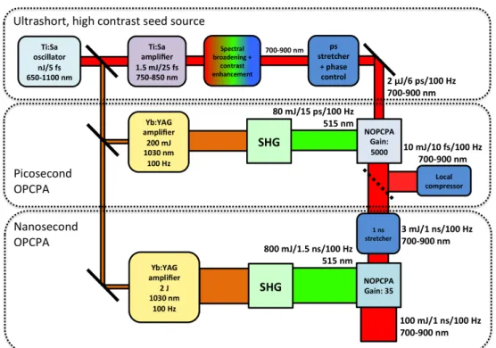
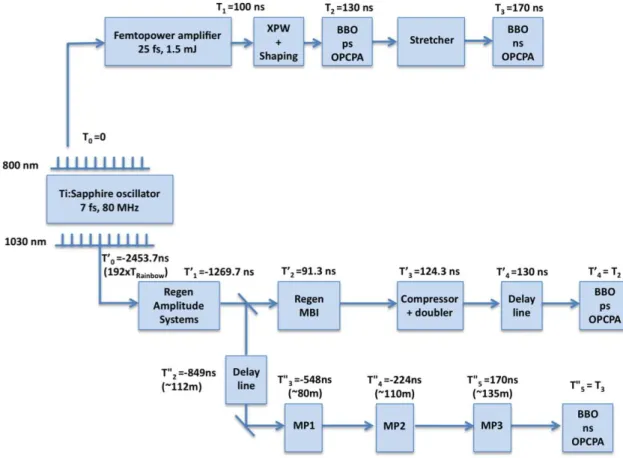
The performances of the front end require a state of the art system never demonstrated before. In order to fight against gain narrowing in Ti:Sa, which prevents simultaneously obtaining very short pulses and high energy, the front end is based on the Noncollinear Optical Parametric Chirped Pulse Amplification (NOPCPA). The main challenges in the development of the system are (1) the pump lasers of the NOPCPA stages, (2) the high contrast requirement of 1012 and (3) maintaining a high repetition rate at the end of the system. A detailed schematic of the front end is presented in Figure 1.3.2. The front end can be subdivided into three parts: the first is the generation of an ultrashort, high contrast seed source for OPCPA and the succeeding parts consist of two OPCPA stages, one in a picosecond timescale and the other in a nanosecond timescale. The main goal of the front end is to deliver 100 mJ pulses with a bandwidth that can support 10-fs pulses.
Figure 1.3.2. Detailed schematic of the front end of the Apollon-10 PW laser.
The front end starts from an ultrabroad Ti:Sa oscillator which delivers 6.8-fs pulses and has a spectrum ranging from 650-1100 nm. Successive amplification in a multipass Ti:Sa amplifier increases the seed source energy from the nJ-level to 1.5 mJ but lengthens the pulses to 25 fs (750-850 nm) due to gain narrowing. Spectral broadening and contrast enhancement is implemented to attain sub-10 fs pulses and improve the temporal contrast from 108 to ~1010. The bandwidth of the
!
pulse is broadened to 700-900 nm. Then in preparation for the picosecond NOPCPA stage, the pulses are stretched to around 6 ps with a bulk glass stretcher and an acousto-optic programmable dispersive filter (AOPDF) allowing precise phase control of the pulse.
The pump and seed sources for the NOPCPA stages are optically synchronized since they are derived from a single oscillator, eradicating the need of synchronizing two independent sources for the pump and seed. The Ti:Sa oscillator output has spectral content at 1030 nm which is amplified in diode pumped, ytterbium (Yb) doped laser amplifier chains and frequency doubled to serve as pumps for the picosecond and nanosecond OPCPA stages. Using diode-pumped technology offers the potential of operating the front end at a high repetition rate and therefore, high average power. Additional advantages include improved energy stability and better beam stability resulting from lower thermal load.
The picosecond OPCPA stage has a gain of 5000. The ultrashort seed must be amplified to 10 mJ with approximately 80 mJ of pump energy. The main advantage of the picosecond OPCPA stage is its capability of improving the contrast of the pulse. Since amplification only occurs during the presence of the pump, anything outside the pump temporal window will not be amplified. An improvement in contrast related to the gain of the amplification stage is expected. A local compressor shall be installed after the picosecond OPCPA stage for pulse monitoring.
Finally, the output of the picosecond stage will be stretched with an aberration-free Öffner stretcher to 1 ns. This nanosecond, power amplification stage only requires a gain of 35 to reach the goal of 100 mJ for the front end. The output is then sent to the Ti:Sa amplifiers for further amplification to reach 300 J before compression.
1.4.FRAMEWORK OF THIS THESIS
The goal of this thesis is to develop the appropriate ultrashort seed source for the Apollon-10 PW laser front end and implement its picosecond OPCPA stage. The approach in the work is mainly experimental but also guided by theory and simulations. A more in-depth description of the Apollon-10 PW front end is presented in the second chapter, including the characteristics of the picosecond pump system used for OPCPA and its synchronization with the ultrashort seed. In the third chapter, the stringent requirements of the Apollon-10 PW seed source are reviewed and approaches to fulfill these requirements are presented. Two techniques for spectral broadening are studied and contrast enhancement via cross polarized wave generation is demonstrated. In Chapter 4, the experimental conditions of the seed prior to amplification are defined. This mostly involves the design of an appropriate seed stretcher. The applicability of using a negative dispersion or positive dispersion stretcher in the system is assessed and the final stretcher design is implemented.
OPCPA is discussed in the fifth chapter, including theory and experimental results. The picosecond OPCPA stage was designed based on simulations using the available experimental parameters. Single and dual stage configurations were tested and preliminary compression results are presented. Conclusions and perspectives of this work are discussed in the last chapter.
T
HEA
POLLON-10
PW
F
RONTE
NDAs mentioned in the first chapter, the Apollon-10 PW front end is divided into three parts: the ultrashort seed source, picosecond OPCPA and nanosecond OPCPA stages. In the first part of this chapter, these sub-systems are briefly discussed to provide a global overview of the front end. Afterwards, the key components: the ultrashort seed and the pump sources, necessary in the implementation of the picosecond OPCPA stage are presented. The starting point of the ultrashort seed source which consists of an ultrabroadband Ti:Sa oscillator and a Ti:Sa multipass amplifier are explained in detail. The picosecond pump, on the other hand, was developed with commercially available amplifiers and under a collaborative effort with the Max Born Institute from Berlin (Germany). Several amplifiers were used to boost its initial pJ energy to 200 mJ. Emphasis is also given to the synchronization of the pump and seed pulses as a crucial aspect in picosecond OPCPA. Furthermore, some components of the nanosecond OPCA stage which have been developed in parallel are also presented. To summarize the chapter, the progression of the development of the laser chain is discussed.
2.1.THE APOLLON-10PWFRONT END SUB-SYSTEMS:AFAST OVERVIEW
The Apollon-10 PW front end is a highly complex system as represented by its detailed block diagram in Figure 2.1.1. To aid in understanding such a complicated laser chain, its three parts— the ultrashort seed source, picosecond OPCPA stage and nanosecond OPCPA stage are introduced in the following subsections to provide a general overview of the system.
2.1.1.ULTRASHORT SEED SOURCE
The starting point of this system is a commercial carrier-envelope-phase stabilized, 80 MHz, octave-spanning Ti:Sa oscillator that also provides an output at 1030 nmn for the pump of the laser chain. The ultrabroad 800-nm main output is seeded into a multipass Ti:Sa CPA amplifier to obtain 1.5-mJ, 25-fs pulses at a repetition rate of 1 kHz. The spectral phase of the 800-nm pulses is actively controlled by an acousto-optic programmable dispersive filter (AOPDF, Dazzler from Fastlite) and the beam pointing stability is controlled by a tip-tilt active mirror leading
to
instabilities of only 50 µrad. Specifications of the oscillator and amplifier are included in section 2.2. These amplified pulses are used to generate 10 fs pulses with a high contrast ratio (CR) >1010 and an energy of few !J in order to seed the ps-OPCPA stage, which is the aim of this thesis.
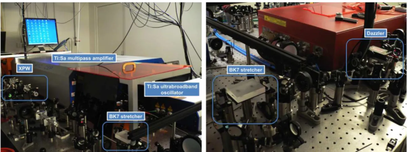
Figure 2.1.2. Parts of the ultrashort seed source implemented in the Apollon-10 PW front end.
The next block for the ultrashort seed source is labelled as XPW and the actual setup is shown in Figure 2.1.2. This represents a compact and highly efficient method for spectral broadening and contrast enhancement based on cross polarized wave generation (XPW). The development of the seed source delivering sub-10-fs and 10-fs, high contrast, CEP-stable pulses is extensively discussed in Chapter 3.
Before the ps-OPCPA stage can be implemented, the seed pulses must be stretched to a duration of several picoseconds to match the pump, permitting efficient energy extraction. Several stretcher configurations were tested to achieve 6-7 ps pulses. Setups utilizing negative and positive dispersion were explored. This is the subject developed in Chapter 4 of this thesis. The final stretcher configuration, represented by the BK7 stretcher and Dazzler blocks in Figure 2.1.1, consisted of a double-passed 7.5-cm long, BK7 glass block and an AOPDF (Dazzler from Fastlite). The actual setup is shown in Figure 2.1.2. The Dazzler, having a 45-mm TeO2 crystal, will be used
to actively control the residual phase mismatch between the ns-Öffner stretcher (section 2.1.3), all the materials of the amplifiers and the final compressor of the Apollon-10 PW laser. After stretching, spatial filtering was performed to ensure an excellent spatial profile for the injection of the ps-OPCPA stage.
!
2.1.2.PICOSECOND PUMP AND OPCPA STAGE
Both pump lasers in the picosecond and nanosecond OPCPA stages have been and are still being developed within the project and will be based on diode-pumped Yb:doped laser amplifiers. This offers two main advantages: (1) direct diode-pumping of crystals offer the potential of efficient operation at repetition rates in the 100 Hz range and (2) Yb:doped gain media possess a relatively large bandwidth, allowing tunability of the pulse duration of the pump from sub-ps to ns pulses. The second advantage is highly suitable for the ps and ns OPCPA stages of the Apollon-10 PW front end. Additionally, chirping the seed and the pump has proven to enhance the gain bandwidth of OPCPA [Zha 11]. The result has been demonstrated with a Ti:Sa pump but can be realized with these flexible, Yb:doped pump sources too.
Figure 2.1.3. Parts of the picosecond pump for OPCPA implemented in the Apollon-10 PW front end.
The amplification of the pJ output from the ultrabroadband oscillator to the mJ pump for picosecond OPCPA is described thoroughly in section 2.4. Pictures of the parts of the picosecond pump are shown above. As an overview, the 1030 nm output was initially amplified from the pJ to the nJ-level with an ytterbium doped fiber amplifier (YDFA) from Keopsys. Afterwards, a CPA configuration was adapted for amplification to the mJ level. A Martinez-type stretcher lengthens the pulse to around 2 ns and was amplified to 2 mJ in a Yb:KYW regenerative amplifier from Amplitude Systemes (S-Pulse). Part of the output was sent to the nanosecond pump while the remaining energy seeded the last amplifier of the picosecond pump. Another regenerative amplifier based on a thin-disk Yb:YAG crystal, developed in collaboration with the Max Born Institute (MBI), increased the energy of the 1030 nm beam to 200 mJ. The output was compressed down to around 15-17 ps with a grating compressor and frequency-doubled in a 4-mm LBO crystal to obtain 80-90 mJ pulses, ~12 ps at 515 nm. These parameters were fixed and the design of the picosecond OPCPA stage revolved around the availability of pump energy and pump pulse duration.
The picosecond OPCPA stage is discussed in detail in Chapter 5. The ultrashort seed source and frequency-doubled pump beam were temporally synchronized (section 2.4) at a 4-mm BBO crystal. A gain of 5000 was desired to amplify 2 !J pulses to around 10 mJ. Single and dual stages were implemented to achieve this goal. Amplification via OPA is an instantaneous process, thus without the presence of the pump, amplification does not occur. Due to the picosecond pump pulse duration and gain, a 3-order of magnitude contrast enhancement was expected outside the duration of the pump beam. Additionally, the amplified pulses were initially compressed to determine the manageability of the accumulated phase in the system. Compression was optimized with the phase control capabilities from the Dazzler (shown in Figure 2.1.2). Once the laser system becomes fully operational, a local compressor will be used to monitor the output pulses of the picosecond OPCPA stage.
2.1.3.NANOSECOND PUMP, STRETCHER AND OPCPA STAGE
The most challenging part of the front end is the nanosecond OPCPA pump. No commercial diode-pumped source is capable of delivering around 2 J, >1.5 ns pulses at 1030 nm and repetition rate of 10-100 Hz. This energy is required to have 1 J, >1.3 ns pulses at 515 nm to pump the final OPCPA stage and amplify the ultrashort seed to 100 mJ. To achieve this goal, three multipass CPA amplifiers are needed to amplify 1 mJ from the Yb:KYW regenerative amplifier. Progress on this part is briefly discussed but is not witihin the scope of this thesis.
At the moment, only the first multipass amplifier (MP1), shown in Figure 2.1.4 has been developed. The amplifier is based on two diode-pumped Yb:KYW crystals which inherently have a high gain and are thus ideal for pre-amplification. First demonstrations of the amplifier produced 20 mJ from an input energy of 1 mJ and pump energy of 180 mJ. Further details on the amplifier are presented in section 2.5.1 and discussed in [Pap 11].
Figure 2.1.4. The first multipass amplifier (MP1) for the nanosecond OPCPA pump.
The two succeeding amplifiers (MP2 and MP3) will be based on Yb:CaF2 crystals that are cooled
!
(>15 nm). Low temperatures enhance its gain cross section, improving its thermal properties and favoring high power/high repetition rate operation [Sie 09, Ric 10]. Each Yb:CaF2 amplifier will
have a gain factor of 10, increasing the energy from 20 mJ to 200 mJ then from 200 mJ to 2 J. After frequency doubling, around 1 J of 515 nm will be available for the nanosecond OPCPA stage.
Similar to the picosecond OPCPA stage, the seed pulses have to be stretched to a nanosecond duration to match the pump pulses. This duration will also be used in the succeeding Ti:Sa amplifiers of the laser chain. Stretching from 6-7 ps to around 1 ns will be performed with an aberration-free Öffner stretcher, which is discussed in more detail in section 2.5.2. Implementation of the stretcher is currently in progress and is shown in Figure 2.1.5.
Figure 2.1.5. Öffner stretcher which will stretch the ps-pulses to 1 ns for the nanosecond OPCPA stage.
Due to losses in the Öffner stretcher, mainly caused by the number of passes through the gratings, only ~3 mJ of the 10 mJ seed energy generated from the ps-OPCPA stage will remain after transmission. This will require a gain of around 35 and extraction efficiency of around 10% to obtain 100 mJ pulses from a pump of 1 J. The main difficulty in the nanosecond regime is the reduced damage threshold of the antireflection coatings of the BBO crystal. As a result, the maximum peak intensity on the crystal should limited to around ~0.5 GW/cm2 for safe and reliable operation. To compensate for this decreased intensity, which is directly related to the gain in an OPCPA, longer crystals must be used to achieve the desired efficiency.
With the global overview of the Apollon-10 PW front end, the parts of each sub-system can now be discussed. The remaining sections of this chapter (2.2-2.5) consist of detailed descriptions of the sub-systems to further aid in understanding the complexity of the Apollon-10 PW front end.
!
!
!
2.2.THE ULTRASHORT SEED SOURCE
The starting point of the ultrashort seed source is based on a commercial Ti:Sa oscillator and amplifier which provide carrier-envelope phase stable pulses. The features of these systems influence the spectral broadening and contrast enhancement stages required for the Apollon-10 PW front end and are therefore explained in the following subsections. Emphasis is also given on how these systems deliver carrier-envelope phase stable pulses.
Figure 2.2.1. (a) Diagram of the ultrabroadband oscillator courtesy of [Can 09]. Spectra of the (b)
ultrabroadband Ti:Sa oscillator and (c) multipass Ti:Sa amplifier.
2.2.1.ULTRABROADBAND TI:SA OSCILLATOR:FEMTOSOURCE RAINBOW
The ultrabroadband Ti:Sa oscillator called Femtosource Rainbow from Femtolasers is a Kerr-lens mode-locked, compact and carrier envelope phase stabilized (CEP) oscillator which delivers 2-nJ, 6.8-fs pulses at a repetition rate of 80 MHz as shown in Figure 2.2.1.a. The spectrum of the oscillator is shown in Figure 2.2.1.b, is ultrabroad arising from the combination of lasing and self-phase modulation in the Ti:Sa crystal [Fuj 03]. Highly beneficial for the Apollon-10 PW laser chain, this single oscillator is used to seed both the signal and pump lines for OPCPA, unlike other systems which require further wavelength shifting for the pump with nonlinear methods such as soliton-based frequency shifting in a photonic crystal fiber [Tav 06a] or the electronic synchronization of two independent seed and pump sources [Wit 06]. A dichroic mirror splits the spectrum between the signal and pump lines (800 nm and 1030 nm output in Figure 2.2.1.a) as indicated by the red and orange shaded areas in Figure 2.2.1.b. Intracavity dispersion is
!
compensated with chirped mirrors (CM) and tuned with a pair of ultra-thin fused silica wedges (W) positioned at Brewster angle. The output pulses are compressed with chirped mirrors as well. Additional extracavity components, such as an acousto-optic modulator (AOM) for the pump (Coherent Verdi, 532 nm) and a PP-MgO:LN crystal (PPLN) are also installed for carrier envelope phase stabilization which will be discussed further in section 2.2.3.
2.2.2.MULTIPASS TI:SA AMPLIFIER:FEMTOPOWER
The optical layout of the Ti:Sa multipass amplifier is shown in Figure 2.2.2 and its spectrum in Figure 2.2.1.c. The system, called Femtopower and also from Femtolasers, delivers 25-fs, 1.5 mJ pulses which are CEP stabilized and have a contrast of 108. The seed from the oscillator enters the system, as indicated by the oscillator input label in Figure 2.2.2. First the seed passes through a Faraday isolator that blocks any back reflections which may re-enter the oscillator. As a CPA, the seed pulses are stretched with CEP prisms (CEP-stretcher in Figure 2.2.2) and two passes in 10 cm of SF-57 glass (Stretcher in Figure 2.2.2). The CEP prisms are used for slow-loop CEP stabilization. The stretched pulses are coupled into the multipass amplifier where the Ti:Sa crystal is cooled at low temperatures (100 K) to prevent thermal lensing and pumped by a Q-switched Nd:YLF laser (Photonics Industries). For the first four passes, the MHz pulse train from the oscillator is amplified. After the fourth pass, the pulse is coupled out of the ‘cavity’ and redirected to a Pockels cell which is set to select the most intense pulse in the train and to decrease the repetition rate to 1 kHz. To suppress any pre-pulses, a Berek compensator [Ber 12] is placed after the Pockels cell for fine tuning of the pulse polarization. Subsequenty, the pulse passes through the Dazzler (25-mm TeO2 crystal, Fastlite) allowing phase control and amplitude shaping to fight gain
narrowing. The pulse then re-enters the multipass ‘cavity’ and retraces the path of the first four passes, but at a different height. For the 9th and 10th passes, a telescope increases the laser beam size to have efficient gain saturation across the whole pump volume. A pick-off prism couples out the pulses which are then redirected by mirrors to the grating compressor. As the pulses exit the system, a beam splitter sends part of the beam to a Menlo APS system, equipped with an f-to-2f interferometer and spectrometer for CEP measurement, which is discussed in detail the Appendix. Additionally, beam pointing is stabilized and actively controlled with piezo-controlled, tip-tilt active mirrors installed at three points in the amplifier: (1) the input, (2) after the 10th pass and before the grating compressor and (3) at the output/input of the next part of the ultrashort seed source. With active control of the pointing stability and a feedback loop, the pointing instabilities in the system are minimized to less than 50 !rad.
Figure 2.2.2. Schematic diagram of the 10-pass Ti:Sa amplifier which provides 25-fs, 1.5 mJ pulses at 800
!
2.2.3.CEP AND STABILIZATION
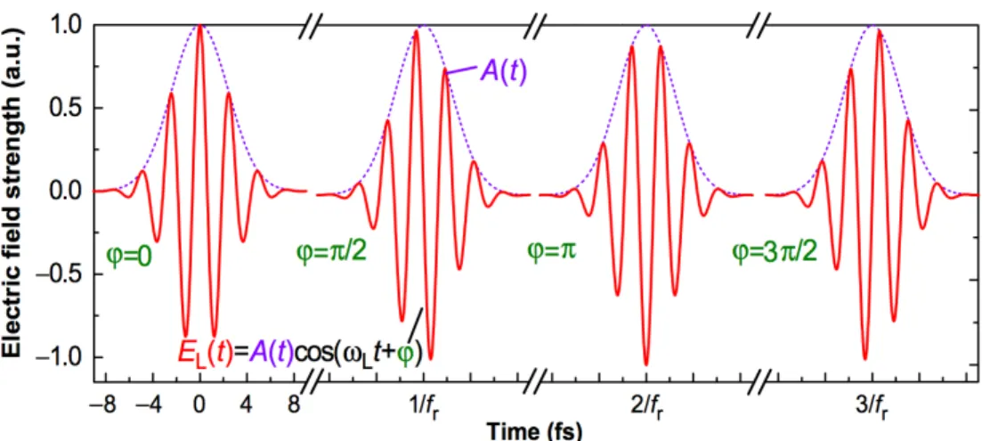
Before discussing how the CEP is stabilized in the oscillator and amplifier, it is useful to define the carrier envelope phase and its importance. An ultrashort pulse can be described in the temporal domain as a product of an envelope
A
(t)
and a carrier wave represented bycos(
!t + ")
as seenin Figure 2.2.3. The carrier envelope phase is the phase difference between the peak of the envelope and the carrier frequency, denoted by
!
. In the figure, the slippage of the carrier envelope phase is shown as the peak of the carrier wave becomes displaced with respect to the envelope. Variations in the phase are easily caused by dispersion as the envelope (group velocity,v
g=
!!
!k
0) and carrier wave (phase velocity,
v
ph=
!
k
0) experience different speeds in a material.
The CEP is crucial for few-cycle pulses since the peak of the carrier wave shifts and will therefore cause a variation in the maximum electric field that reaches the target. For some few-cycle, high-intensity experiments such as harmonic generation this phase is important [Boh 98].
Figure 2.2.3. Slippage of the carrier envelope phase as seen by the displacement of the peak of the carrier
wave (red) with respect to the peak of the envelope (violet). Diagram courtesy of [Dom 04].
In the Apollon-10 PW system, both the oscillator (Femtosource Rainbow) and multipass amplifier (Femtopower) deliver pulses with stabilized CEP. For CEP stabilization in the oscillator, the laser pulses are focused into a PP-MgO:LN crystal where difference-frequency generation (DFG) occurs between the edges of the pulse spectrum and SPM is induced [Fuj 05] as shown in Figure 2.2.4. This DFG signal inherently has no CEP phase (
!
= 0) and as it interferes with the SPM broadened laser spectrum, the beat note can be measured and represents the carrier envelope phase frequency,f
CE which is related to the repetition rate byf
CE= !! f
r2"
. A fast acousto-optic modulator is used to control the pump power which induces a shift on the mode-locked spectrum [Hel 02] and forces thef
CE to be equal tof
r4
. The CEP change after each successive pulse will then be equivalent to 0.5!
as shown in Figure 2.2.3. Asf
CE slowly drifts during the operation of the oscillator, automatic adjustment of the CEP is done with a pair of intracavity wedges.
Figure 2.2.4. Representation of CEP measurement in the oscillator. DFG occurs between the high frequency
(nfast) and low frequency (nslow) components of the spectrally broadened pulse. The beat frequency between
the DFG and SPM broadened pulse is equivalent to the carrier envelope phase frequency fCE. The image is
provided by Femtolasers and adapted from [Fuj 05].
For the mutipass amplifier (Femtpower), the Pockels cell is triggered by
f
CEO= f
r4
so only pulses of the same CEP are amplified. The CEP is also very sensitive to beam pointing instabilities which was evident in oscillators using prisms for cavity dispersion instead of chirped mirrors [Hel 02]. This occurred since the beam pointing instabilities would cause changes in beam path through the prisms, varying the amount of dispersion acquired by the pulse. For the amplifier, this is exploited to control the slow drifts in the CEP. The CEP prisms are used to slightly adjust the material dispersion experienced by the pulse by mutual translation of the prism pair [Gre 09]. The slow drift in CEP is measured by an f-to-2f interferometer (refer to Appendix) in the Menlo APS system (see Figure 2.2.2). The system generates an error signal that is sent to transducers to control the CEP prism pair. The CEP stability of the output pulses is around 200 mrad, as shown in Figure 2.2.5.Figure 2.2.5. Measured CEP drift of 200 mrad rms of the amplifier for over 200 s.
After the commercial Ti:Sa systems, the succeeding parts of the seed source consist of spectral broadening and contrast enhancement stages which is the focus of Chapter 3 and stretching of the pulses to match the picosecond pump as discussed in Chapter 4.
!
2.3.THE PICOSECOND OPCPA PUMP
In this section, each of the Yb-based amplifiers mentioned in the fast overview as part of the picosecond OPCPA pump are discussed in detail. Implemented in a CPA scheme, these amplifiers boost the pJ output of the oscillator to 200 mJ and is subsequently frequency doubled, providing around 80-90 mJ at 515 nm for the picosecond OPCPA stage. The pump line of the laser chain was developed by Dimitris Papadopoulos and Alain Pellegrina of the Apollon-10 PW front end team. The picosecond pump is unique and is the state of the art in terms of repetition rate (100 Hz) and energy (80 mJ at 515 nm). The first part of which is schematically represented below whereas the actual picture was shown earlier in Figure 2.1.3.
Figure 2.3.1. Schematic of the amplification of the 1030 nm output from the ultrabroadband oscillator.
Preamplification occurs in a Yb-doped fiber amplifier, the pulse is stretched and then further amplified in a commercial regenerative amplifier.
2.3.1.YTTERBIUM DOPED FIBER AMPLIFIER
Depicted in Figure 2.3.1, the 1030 nm output of the oscillator is seeded directly into the ytterbium doped fiber amplifier (YDFA). Its initial spectrum from the ultrabroadband oscillator is shown in Figure 2.3.2 together with its beam profile. The output was coupled into a single mode fiber that was connected to the input of the YDFA and the whole pulse train at 80 MHz was amplified. Specifications of the amplifier suggest that with an input pulse having an average power of 0.1 mW (1.25 pJ) and a bandwidth of 4 nm, 1.9-nJ, 700-fs amplified pulses are expected. With a slightly higher input energy (~0.16 mW, 2 pJ), the output of the oscillator was amplified to around 3.75 nJ. The spectrum of the amplified pulses was still broad, having a FWHM of 14 nm but due to the broader bandwidth of the input pulses and the dispersion of the fiber, the output pulse duration was estimated at 2.8 ps.
Figure 2.3.2. (a) Spectrum and (b) beam profile of the 1030 nm output of the ultrabroadband oscillator
(Femtolasers Rainbow), (c) Output power with respect to pump current of the YDFA and (d) output spectrum.
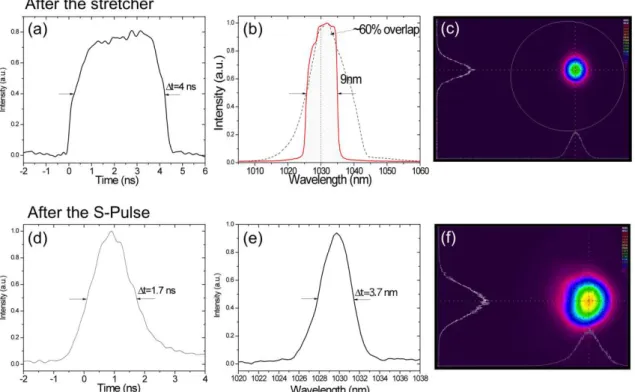
Figure 2.3.3. (a-c) Temporal, spectral and beam profiles of the 1030 nm pump after the grating stretcher, the
red line in (b) shows the output spectrum while the dashed line is the input, (d-f) temporal, spectral and beam profiles after amplification from the S-Pulse to 2 mJ.
!
2.3.2.STRETCHER AND S-PULSE AMPLIFIER
The CPA scheme was implemented after the YDFA for amplification to higher energies. The output of the YDFA was stretched to around 4 ns with a 4-pass grating stretcher, illustrated in Figure 2.3.1. The Martinez-type stretcher used a single grating (1825 l/mm) and its beam path was folded for compactness. The temporal profile of the pulse was square-shaped as shown in Figure 2.3.3 and because of clipping in the stretcher, specifically at the folding mirror (left mirror in Figure 2.3.1), the bandwidth of the output spectrum was reduced to 9 nm. The beam profile was excellent and was injected into the next part of the system, a commercial regenerative amplifier (S-Pulse, Amplitude Systemes) based on diode-pumped Yb:KYW crystals.
The S-Pulse contains a pulse picker which permits the amplifier to operate in the single-shot regime up to repetition rates of 1 kHz. The pulses were amplified to 2 mJ and their resulting temporal and spectral profiles are shown in Figure 2.3.3. Further reduction of the bandwidth to 3.7 nm was caused by gain narrowing and the corresponding measured pulse duration was around 1.7 ns. The output of the S-Pulse was split into two, around 0.2-0.5 mJ went to the last amplifier for the picosecond pump while the remaining energy was used for the nanosecond pump.
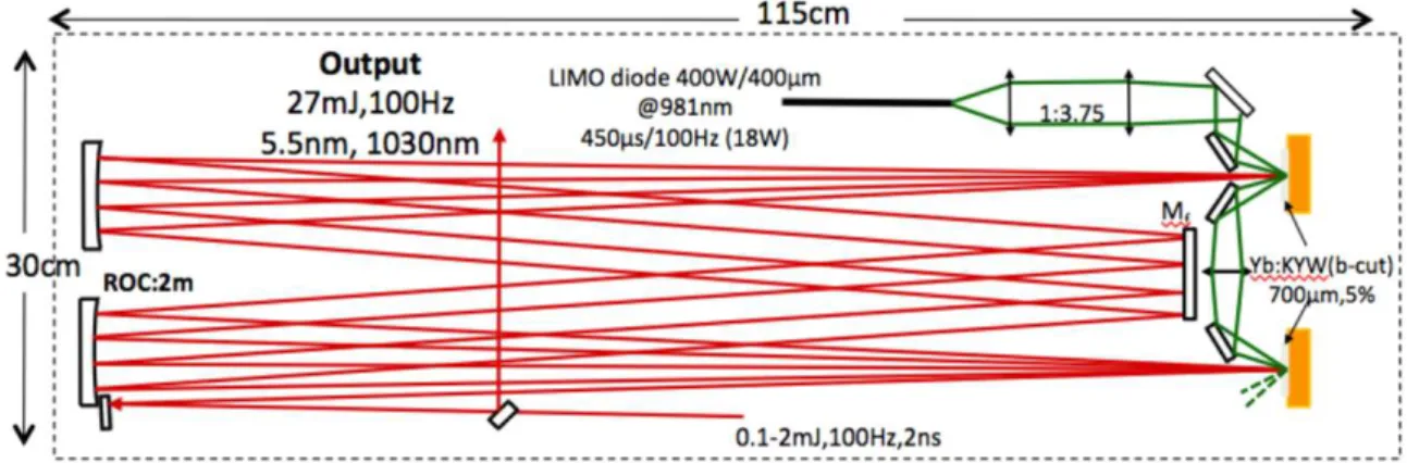
2.3.3.MBI AMPLIFIER
The last amplification stage of the picosecond pump laser is a Yb:YAG thin disk regenerative amplifier from MBI with the same design as in [Tum 09]. An industrial thin disk head provided by Trumpf was used as a gain medium. A regenerative cavity was built around this gain module as shown in Figure 2.3.4. The BBO pockels cell, which was also developed by MBI, fixed the repetition rate of the amplifier to 100 Hz. In order to reduce the heat load on the disk, the pump diode assembly was operated in quasi-continuous mode at 100 Hz and had a pump duration of 0.7 ms. Outcoupling of the amplified beam was carried out with a Faraday rotator associated to a polarizer and half-wave plate. In addition to having a maximum energy of 200 mJ, the characteristics of the pulses are shown in Figure 2.3.5. Gain narrowing was unavoidable especially in Yb:YAG as the spectral bandwidth of the pulses shortened from 3.7 nm to 1.9 nm and the measured temporal duration was around 1 ns.
Figure 2.3.4. Schematic of the MBI amplifier which consists of a regenerative cavity built around a
Figure 2.3.5. (a) Temporal, (b) spectral, and (c) spatial beam profiles of the output pulses from the MBI
amplifier.
2.3.4.COMPRESSION AND FREQUENCY DOUBLING
The pulses were compressed using a highly dispersive transmission grating pair (1825 l/mm) with an overall efficiency of 74%, leading to 150 mJ and pulse duration of 15-17 ps. The pointing stability of the 1030 nm output was measured to be <5 µrad owing to the remarkable stability of the regenerative amplifier and the transmission grating based compressor. The IR pulses were frequency doubled in a 4-mm thick LBO crystal in a critically phase matched type I configuration to obtain at maximum, ~95 mJ pulses at 515 nm. The efficiency for second harmonic generation was around 63% and the global efficiency including losses from the compressor was ~47%. The pulse duration was estimated to be around 12 ps due to the quadratic intensity dependence of SHG and an excellent pulse to pulse energy stability of 1.2% rms was achieved from working in the saturation regime. The spatial profile of the pump beam is shown in Figure 2.3.6.b and this will be used for the picosecond OPCPA stage. The variable parameter of the pump for the OPCPA stage was its energy which was controlled by a half-wave plate and polarizer. The pump pulse duration was fixed to around 12 ps as a result of the difficulties in adjusting the compressor whose grating separation reached around 2 m.
Figure 2.3.6. (a) Compression of the MBI output with a 2-pass grating compressor and frequency doubling
with a 4-mm LBO, (b) beam profile of the 515 nm output.
Prior to setting up the OPCPA stages, the picosecond pump and stretched ultrashort seed pulses must be temporally synchronized. In the picosecond timescale, issues including temporal jitter become more crucial as compared to the nanosecond timescale and are therefore discussed in the following section.