f
MITLibraries
Document Services
Room 14-0551 77 Massachusetts Avenue Cambridge, MA 02139 Ph: 617.253.5668 Fax: 617.253.1690 Email: docs@mit.eduhttp://libraries. mit. edu/docs
DISCLAIMER OF QUALITY
Due to the condition of the original material, there are unavoidable
flaws in this reproduction. We have made every effort possible to
provide you with the best copy available. If you are dissatisfied with
this product and find it unusable, please contact Document Services as
soon as possible.
Thank you.
Some pages in the original document contain
Design and Manufacture of the 2003
2.007 Wireless Control Boxes
by
Eric Varady
Submitted to the Department of Mechanical Engineering
in Partial Fulfillment of the Requirements for the
Degree of
Bachelor of Science
at the
Massachusetts Institute of Technology
June 2003
© 2003 Massachusetts Institute of Technology
All rights reserved
The author hereby grants to MIT permission to reproduce and to distribute publicly
paper and electronic copies of this thesis document in whole or in part.
/
Signature of
_
...
.,.y.:...
/...
...
D arment of
M
chanical Engineering
_F"'---"-~
~ ~
~May
~
16,
2003
C ertified
by
...
. ...
. ..
... .... ... .. ...
.
...
Alexander H. Slocum
Professor Mechanical Engineering
Thesis Supervisor
/'7
, IDESIGN AND MANUFACTURE OF THE 2003 2.007 WIRELESS CONTROL BOXES
by ERIC VARADY
Submitted to the Department of Mechanical Engineering On May 23, 2003 in partial fulfillment of the requirements for the Degree of Bachelor of Science in
Mechanical Engineering ABSTRACT
A new smaller, lighter, and more durable wireless control box was designed and built for use in the 2.007 Design Contest. The new units can also be commanded by an external controller via a standard serial interface.
Thesis Supervisor: Alexander H. Slocum Title: Professor of Mechanical Engineering
Introduction:
In 2001, the 2.007 Design Contest switched from a tethered to a wireless control system. Eliminating the tether facilitated greater freedom of movement and ease of control. Unfortunately, this first control box was large, heavy, and electrically vulnerable. It had open holes in its enclosure so its heat sinks (which were not
electrically neutral) could dissipate heat and it had bulky rubber bumpers on its sides for added shock absorption.
The discontinuation of one of the first-generation box's critical components coupled with the need for autonomous control of the box via an external controller initiated the design of a new control box. The goals were to make the new box smaller, lighter, and more durable. There would be two means of input - radio and serial. To make the box less prone to failure due to student wiring mistakes, the box would be electrically protected against reversed batteries and have a more thoughtful pin layout to minimize confusion and error. New components would eliminate the need for exposed electrically-hot heatsinks and would make the box compatible with alkaline batteries as an input.
Control Box Fabrication Instructions:
The fabrication of the control box has been separated into three sections: First come the operations done on the bottom of the plastic enclosure and the subsequent mounting of hardware to it. Second is the creation of the "top insert" - four Novak Spy electronic speed controllers (ESC) mounted to an acrylic support and wired to a terminal block. Last is the electrical wiring of all remaining components together. See Appendix
for a complete bill of materials. Section One: The Plastic Enclosure
The plastic enclosure and acrylic insert are cut on the Media Lab's laser-cutter. The laser-cutter was chosen over other manufacturing methods (e.g. CNC Mill, waterjet, etc) because it is fast, easy to program, capable of cutting sharp corners, and allows for easy and repeatable work-piece fixturing.
The Bud Industries' plastic enclosure comes with eight brass inserts - four for the screw attachment of the clear plastic lid, and another four embedded in its inner bottom surface. Because the laser's reflection off these metallic objects would pose a safety risk, the four brass inserts shown in Figure 1 are removed with a mill prior to laser-cutting.
7-Figure 1. Top view of the plastic enclosure with the lid off. The highlighted red
items are the plastic cylinders (0.25" high) housing threaded brass inserts. The laser's path intersects these metallic objects, so they must be removed before laser-cutting.
To prevent vaporized plastic from accumulating on the enclosure's outer surfaces (especially in the areas around the raster-etching of the serial-jack hole), the box is covered with a layer of masking tape prior to laser-cutting. Once the box is cut, the tape is removed and the box is cleaned with rubbing alcohol. The laser-cut clearance holes for machine screws are countersunk to the sizes specified in Figure 2.
·
. * -04
', ,. . ' '. , , ^ -. , ' , .'. 'y... ..£ , l ' ' ' ' ' ' ' . ', . ,,. ., , ,. .. , S,0S
04
if.
es
..- .... ':...:....:.'. ~': _'._, :....'..::.2 .. ,.'.... " . ' Jy J - -~~~~~~~~~~~~~~~~~~~~~~~~~~~~~~~~~~~~~~~~~~~~~~ I x, IJIn preparation for epoxying the motor and battery outlet plugs to the inner surface of the enclosure, the box's inner surface and the corresponding surfaces of the plugs are lightly sanded. Five-minute plastic epoxy is applied to the plug and it is positioned and screwed into place. The panel-mount phone-jack receptacle is snapped into position and epoxyed for added reinforcement.
Hex standoffs are screwed into place with #6 spring lock-washers as shown in
Figure 3.
I'MI
Figure 3. Quarter cross-section of the plastic enclosure showing the installation
of the hex standoffs. A spring lock washer (blue) is used to prevent the flathead #6 screw from vibrating loose.
The [MiniSSC is stacked on top of a Battery Booster (with the use of the 0.25" aluminum standoffs supplied with the Battery Booster) and bolted into position inside the box with #4 spring lock-washers and nuts. Figure 4 shows the plastic enclosure with the two plugs, four hex standoffs, MiniSSC, and Battery Booster.
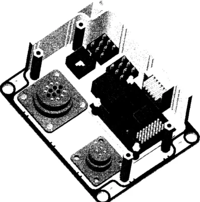
Figure 4. Two plugs, four hex standoffs, MiniSSC, and Battery Booster mounted
to the plastic enclosure (two of its walls have been removed for easier viewing). The MiniSSC is mounted above the Battery Booster (shown in orange) and is separated by the four 0.25" round unthreaded standoffs (shown in purple) that are supplied with Battery Booster. This combination is mounted to the enclosure with fur #4 screws, lock washers, and nuts.
Section Two: The Top Acrylic Insert
Wiring the Novak Spys to the terminal block is most easily done when all components are already mounted to the acrylic insert. The insert is created on the Media Lab's laser-cutter from 1/16" thick acrylic sheet. As shown in Figure 5, the Spys are aligned on the insert such that their PWM cables pass through the rectangular cutouts. They are mounted to the insert with Scotch penrmanent double-sided tape.
Wire<; (shown n
ire berit down p ' d tlroLg the'sc holes
Figure 5. Alignment of Novak Spys and Phoenix Contact terminal block on the
laser-cut acrylic insert. The Spys are mounted with Scotch permanent double-sided tape, and the terminal block is mounted with foam double-sided mounting tape.
The terminal block consists of a Phoenix Contact terminal plug and corresponding receptacle snapped together into one unit. This block is then aligned on the insert as shown in Figure 5 and attached with double-sided foam mounting tape. The Spys' motor and battery plugs are cut off and discarded. Each of the motor and battery wires are cut to length, stripped, and inserted into the terminal block according to the wire diagram
Figure 6. Control system electrical wiring diagram.
The 0. lItF capacitors supplied with the Spys are inserted into the terminal block as shown in Figure 7. These eliminate electrical noise generated by the motors, which can interfere with radio reception. After a careful inspection is conducted to ensure there are no shorts across any of the wires entering the terminal block, the terminal block's screws are tightened down.
Figure 7. Installation of 0.1 I F capacitors into the terminal block. The red and
black wires run from the four Novak Spy ESCs (not shown) to the terminal block. See Figure 6 for further wiring detail.
On the other side of the acrylic insert, each of the Spys' switches are cut off and the two wires are soldered together. This permanently activates each Spys' Battery-Eliminator-Circuitry (BEC), which is used to power the receiver, LEDs, CMOS switching chip, and MiniSSC.
Highly-flexible Daburn 18-gauge wires, shown in Figure 6 as the thick yellow and green wires, are inserted into the terminals of the terminal block on the side farthest from the ESCs (i.e. into the empty terminals shown in Figure 7 that are on the far side of the terminal block). Each wire is 6 inches long and has crimped to its other end an AMP socket. The short wires in Figure 6 are "jumpers" connecting the battery terminals in parallel. They are made of Daburn wire that has had its insulation stripped off and replaced with 1/16" OD heat shrink. This modification reduces the wire's overall OD, allowing two wires to fit in each terminal of the terminal block. Following the electrical schematic in Figure 6 and the capacitor installation method in Figure 7, the appropriate adjacent battery terminals are connected with 10F electrolytic capacitors. Electrolytic capacitors are polarized, so careful attention must be paid to ensuring the positive terminal of the capacitor is inserted into a positive battery terminal. The capacitors explode when improperly wired. Once all wires and capacitors are inserted into the terminal block and an inspection for short-circuits conducted, all remaining terminal block screws are tightened down.
Section Three: Wiring All Components Together
Follow Figure 8 to appropriately solder the connections between the pins of the two NKK illuminated push-button switches. In Figure 8, bold black lines show the pins soldered together. Solder to each of the switches' colored pins 5" of 24-gauge wire of the same color. Follow Figure 9 to crimp a MTA 3-pin receptacle to these three colored wires now soldered to each of the switches. Pay careful attention to the orientation of the positive-locking mechanism to ensure that the red wire enters Pin 1 of the receptacle.
l -[ZIZ I l l _ : __ -l l
IZI
L. , I Ii
+ i__ i I~~~~~~~
I w l I cmFigure 8. Wiring diagram for the red and green NKK push-button illuminated
switches. Note the orientation of the switch based on the "+" and "-" labeled on each switch. Bold black lines signify soldered pin-to-pin connections. Colored pins signify the color wire that should be soldered to the appropriate pin.
WNMJ
Psn2I 3lr
A
i. , J.
Figure 9. Colored wiring diagram for the 3-pin MTA positive-locking receptacle
for each wire soldered to the NKK switches
Snap a spring-loaded flip-cover to each switch and follow Figure 10 to properly insert and orient the switches into the correct square cutout in the plastic enclosure (note the appropriate orientation of the spring flip-cover with respect to the enclosure). To facilitate easy replacement of the spring-loaded flip-covers, these switches are not glued permanently into the box.
E __- l
425
A
Figure 10. Placement of the two NKK switches and correct orientation of their
spring-loaded flip-covers.
As shown in Figure 11, crimp a two-wire MTA receptacle to the red and black wires exiting the Battery Booster.
P~n1
O"n
ri"nd
Figure 11. Colored wiring diagram for the 2-pin MTA positive-locking
receptacle for the Battery Booster's two input power wires.
Follow Figure 6 to wire the remaining components of the system together. When inserting the Daburn wires into the battery and motor plugs, pay careful attention to which wire enters which hole of the plugs.
The appropriate crystal is inserted into the radio receiver and secured with electrical tape to prevent it from vibrating loose. See Table in the Appendix for a complete frequency chart. The receiver is mounted to the inner side wall of the enclosure using the same permanent double-sided tape used to mount the Novak Spys. Figure 12 updates the enclosure shown in Figure 4 with the addition of the two switches, the snap-in serial jack, and the receiver.
"Connectamundo" pin-to-pin wire connectors are used to connect the MiniSSC and radio receiver to the PCB. Because Connectamundo connectors do not use a positive lock, all are reinforced with electrical tape to protect against vibration.
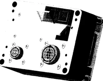
Figure 12. In addition to the items shown in Figure 4, displayed here are the
mounted serial jack, two switches, and radio receiver. The receiver is attached to the enclosure's inner side wall with permanent double-sided tape.
Parts Selection (Major Problems and Decisions):
Electronic Speed Controller Selection
A new Electronic Speed Controller, or ESC, was needed for two reasons: The Novak units used in the previous control boxes had been discontinued. Second, the lower current requirements of the newly selected Tamiya motors allowed for a smaller ESC unit, reducing the overall size of the box. The newly selected ESC was required to be programmable to allow for variation among throttle joysticks. As seen in Table 2 in the Appendix, the Novak Spy ESC best fit our requirements. As an added bonus, the Spy does not have (or need) an external heat sink.
Radio Selection
Again driven by the desire to shrink the overall size of the control box, a GWS Naro radio receiver was selected for its small size compared to its Futaba predecessor. A 6-channel Naro was chosen over the 4-channel version to allow for expandability should
Wire Selection
Each Novak Spy has highly-stranded 18-gauge wires for its motor and battery connections. The large number of high-current wires being squeezed into a small plastic enclosure required the use of the most flexible 18-gauge wire readily available. Securing identical Novak wire from the manufacturer was unreasonably expensive (approximately
$400 per 100 ft.) The most flexible, reasonably-inexpensive, and readily available alternative was Daburn "test-lead wire." Though it has unusually thick insulation, this 18 gage 65/36 wire (65 strands of 36 gauge wire are combined to form this 18 gauge wire) is far more flexible than standard 18 gauge 16/30 with thinner insulation. The large number of strands also increases the current-capacity of each wire.
Serial Interface Selection
For autonomous control, rather than have an external microprocessor spend a large percentage of its CPU cycles generating PWM signals to drive the control box's ESCs, it was decided to include a serial interface in the control box. Serial data entering the box's RJ- 11 phone jack is converted by an on-board PIC from digital values ranging
from 0-255 to the necessary PWM waveforms. Two products were available to accomplish this job, but only the Scott Electronics' MiniSSC was pre-assembled and proven (I had used it with great success in a prior UROP project). In addition, the MiniSSC can control of up to eight ESCs, allowing for future expandability. The
MiniSSC requires a supply voltage of 7-15V, so Medonis Engineering's "Battery Booster 12" was included in the control box to boost the 5V provided by the ESC's BEC to 12V for MiniSSC operation.
Switch Selection
The selection criteria for the switches controlling power to the system and selection of radio or serial input were the following:
* illuminated LED preferable over incandescent bulb for longer lifetime * panel mountable
* capable of being fitted with a spring-mounted protective cover to prevent inadvertent switching.
NKK switches were selected because they fit these criteria and were available from Digikey.
Diode Selection
One of the shortcomings of the previous control box was the lack of reverse-voltage protection. Students in 2.007 often accidentally wire their batteries in reverse and destroy the box's electronic components.
It was decided that the new control box would be protected against this situation with a diode and an alarm.
One option was to wire a reverse-biased diode across the battery leads. This wiring scheme would protect the system from a reversed battery by shorting its current across the diode rather than through the other electronics. Though this setup would not alter the battery voltage viewed by the system under normal operation, the selected diode
would have to be large enough to handle the current drawn (and heat generated) by a short circuit. In addition, the shorted batteries would heat up and possibly explode.
A diode wired in series with the system's electronics, though less efficient under normal operation (due to its constant 0.6V voltage drop), would not short a battery wired in reverse. A piezo buzzer (protected by its own diode) wired in reverse-bias across the battery would then sound an audible alert without any damage done to the system or batteries. This wiring scheme was deemed preferable, and a diode capable of handling up to 25A was selected (far more current than two sets of alkalines can source). If NiCd or NiMH batteries are used in the future, this diode should be upgraded to 50A capacity; each of the four ESCs is capable of drawing a maximum of 12 amps.
Box Selection
The redesign of the control box presented an opportunity to substantially reduce its size and weight. Searching for a plastic enclosure, the critical design criteria were that it be sturdy, capable of being cut with a laser, available with brass threaded inserts (for repeatedly screwing the lid on and off), and a clear plastic lid (for easy viewing of the ESC's LEDs without cutting holes in the box). The box selected from Bud Industries was available through Digikey and in addition came with a NEMA seal for a secure lid fit (though the control box is NOT watertight). As an added bonus, the acrylic insert (on which the ESCs are mounted) can be clamped in place between the top of small plastic protrusions on the inside walls of the enclosure and the underside of the box's lid (as shown in Figure 13). The hex standoffs hold the acrylic insert in place when the lid is removed for ESC calibration or service.
Figure 13. Cross-sectional view of the acrylic insert clamped in place between
the lid and the small plastic protrusions in the inner walls of the enclosure. The screws passing through the insert into the hex standoffs keep the insert in place when the lid is
removed for calibration or service. Motor and Battery Plug Wiring
. i j i i I
separate plugs solved the second. Thoughtful layout of the pins in each plug further minimizes students' confusion.
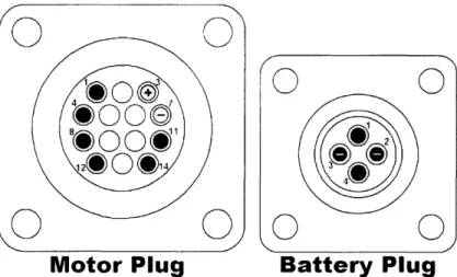
For the 14 pin motor plug, a symmetric layout was chosen such that pairs of motor leads reside next to each other. This pin layout can be seen in Figure 14. The colors correspond to the labeled throttles on the podiums. For each pair of motor leads, the pin labeled with the lower number is "positive" when the throttle is pushed forward.
Motor Plug
Battery Plug
Figure 14. Pin layout for the motor and battery outlet plugs.
For the battery plug, a 4-pin plug with two pins per battery pole was used to double current capacity. By choosing pins across from each other to be the same pole, there is less likelihood of students improperly wiring their plug than if the paired pins were adjacent. See Figure 14 for the battery plug pin layout.
Switching Between Serial and Radio:
The new control box has two input devices: radio and serial. Both devices each output four PWM signals. A device had to be selected or designed that would accept as inputs these two sets of four signals, and based on the user's preference, output only one of the two sets to the four ESCs. Below are the three designs considered.
Simplest Solution - A Four-Pole-Double-Throw (4PDT) Switch
A 4PDT switch would have been by far the easiest means of routing two sets of four input signals to one set of four outputs. A simple wiring diagram for such a 4PDT switch arrangement is shown in Figure 15.
0
©
J
/I
f I
ESC 1
2
.1
/
3
adold
1
Rdo I1
ESC 2 ESC 3 ESC 4
5 8 11
4 7
9
102
2
so
d3
SoI4
M
RadIo 2 Radio 3 RadIo 4
Figure 15. Wiring diagram for the implementation of a 4PDT switch. The two
sets of four PWM signals are wired into the bottom row of pins. The position of the switch determines which set of four signals are routed to the four Novak Spy ESCs. The horizontal dashed line signifies that the four internal switches move in unison.
This method would have also been the least expensive, but was not selected because it would have required lots of soldering, would have appeared "ugly," and would have not allowed for illumination. An external LED from the switch would have allowed for illumination, but a 5PDT switch (the fifth pole would drive the LED) could not be found. In retrospect, the entire project could have been completed far earlier and with much less uncertainty had this method been implemented. Soldering of a PCB actually ended up being far more work than a simple 4PDT switch with 12 leads would have been. Medium Solution - A 4PDT Relay
Using a 4PDT relay instead of a 4PDT switch separates the switch and the switching method. The switch can be a simple illuminated single-pole-single-throw (SPST) unit that activates a 4PDT relay on a printed circuit board (PCB) within the control box. It is the relay that handles the routing of the four PWM signals. Figure 16 shows a simplified wiring diagram.
Figure 16. Wiring Schematic of a 4PDT relay (as shown in the relay's
specification sheet). This schematic is very similar to that of Figure 15. Though the pin numbers are different, this relay effectively houses a 4PDT switch which is triggered by a high "switch" voltage across pins 13 and 14. The above relay also shows a LED wired in parallel to the "switch voltage" for visual feedback.
Though this method was prototyped and worked as desired, there was concern about the effects of external magnetic fields on the relay. Students often mount the control box to their machines with strong ceramic magnets. In close proximity to these magnets, the control box's internal relay may be overpowered and unable to switching properly (a mechanical relay makes or breaks its electrical connections by using tiny
electromagnets to pull signal-carrying wires together or apart). Complex Solution - A Digital Multiplexer
Since a PWM signal is essentially a series of alternating 's and 0's (its "low" is 0V and its high is 5V), a four channel digital CMOS multiplexer (mux) can be used to route one of the two sets of four inputs to the one set of four ESC outputs. A custom PCB was manufactured by PCB Express that incorporated the CMOS mux, supporting electrical components (resistor network and capacitor), resistors necessary for powering the switches' internal LEDs, and pin connectors. Figure 17 shows the physical layout of the PCB, and Figure 18 shows its electrical wiring schematic.
Figure 17. Custom PCB layout. Red traces are wires on the top layer, and blue
traces are wires on the bottom. Purple traces show areas on the board where traces overlap both on the top and bottom.
rcvr
Figure 18. Electrical wiring schematic of the custom PCB.
-I
I
4.8V. A sufficiently high "no-load" alkaline battery voltage must be supplied so that when motors stall and high currents are drawn, the reduced battery voltage never falls below this minimum working voltage. An experiment was done with multiple Tamiya motors operating at stall powered by various combinations of alkaline cells wired in series (for higher voltage) and parallel (for added current-sourcing capacity) The experimental data showed that two parallel sets of six alkaline AA batteries wired in series (6*1. 5V=9V), for a "no-load" supply voltage of 9V, could source sufficient current for motor torque requirements while maintaining the supply voltage above 5.5V in all possible current-draw situations.
The radio receiver, CMOS mux, and Battery Booster (for MiniSSC) are designed to operate within a voltage range of 4.8V-6V. In addition, the LEDs within the switches operate within a very narrow voltage range of +0. IV of their operating voltage, and a supply voltage that varies between a "no-load" 9V and a "stall" 5.5V is out of
specification. A voltage regulator that can convert a varying voltage input into a steady 5V output would serve all of these devices. The Spys "Battery Eliminator Circuitry" is designed to be used for this exact purpose.
Figure 19 demonstrates the voltage changes that occur within the control box as current flows from the batteries to the motors and internal electronics. The 9V supply voltage first sends current through a diode which reduces the supply voltage by 0.6V. The remaining 8.4V powers the ESCs (and is the maximum voltage the motors are
capable of seeing). One ESC's BEC reduces this varying supply voltage to a constant 5V to directly power the radio receiver and CMOS mux. This 5V is further reduced to 2.0V via series resistors to power the switches' LEDs. Lastly, this 5V is also passed to the
Battery Booster, which boosts it to 12V to power the MiniSSC.
9V
Battery
Input
d 8.4V (Valiable 0-8.4V)--- --- -- -- ---
-
4 Motors
Radio Reciever
CMOS Mux
Battery Booster 12V
MiniSSC
2 Switches' LEDs
Figure 19. Flow diagram which shows the changes in voltage within the control
General Specs / Quick Reference:
Control Box Dimensions: 2.50"x4.52"x3.55" (see Figure 20) Weight: .95 lbs
Voltage In:
* Power Supply: 6V to 9V * Alkaline Cells: 6 cells (9V)
* NiCd or NiMH cells: 5 to 7 cells (6V to 8.4V)
Voltage Out: OV to (Vin-0.6V)
* Vin is dependant on the current drawn from the batteries * 0.6V drop is due to the series diode.
Current Out: Max 12 amps Per Motor
K - . I I
-
Box Operation and Troubleshooting:
Radle/Serlal Power Butten Toggle
\ 1~~~~~~~~~~~~~
Serial Imput
Amp 4-pin Amp 14-pin Battery Cennecter Meter Connecter
Figure 21. Bottom view of the control box (without steel sheet metal cutouts
attached).
*
Red Switch: Power (Illuminated = ON)* Green Switch: Radio/Serial Input (Illuminated = serial input) * Spy Calibration:
I. Disconnect motor plug.
2. Hold down the Spy's button until the LED glows solid red.
3. Move corresponding throttle to full-forward until the Spy's LED glows solid green.
4. Move throttle to full-backward until the LED glows blinking-green. 5. Release joystick to neutral and wait for the LED to return to glowing solid
red.
6. Resume normal operation.
* If a Spy's LED does not glow solid red when the corresponding throttle is in the neutral position, re-calibrate it.
* If a box emits loud buzzing, the batteries are wired incorrectly. Disconnect the batteries immediately and investigate.
* Each Spy is capable of sourcing a maximum of 12 amps to the motors. * If the box not responsive:
1. Make sure the red power switch is on and the green input-selector switch is set appropriately.
Recievew
tMre podeMM I
Figure 22. Control system functional schematic.
Future Work:
Diode Upgrade
IfNiCd or NiMH batteries are to be allowed in the future, the diode used to protect against an improperly-wired battery should be upgraded to 50A capacity (each of the 4 ESCs is capable of drawing a maximum of 12A 4x12=48A).
Add Channels
Both the receiver and the MiniSSC are capable of supporting two additional channels, but the PCB, as it is currently designed, cannot. One option that does not require any PCB redesign is to add a second identical PCB and use it in much the same way. A second option is to redesign the PCB to use an 8-channel mux. A third option is to replace the entire digital "complex" solution and use a "6PDT Switch" (variant of the 4PDT switch discussed earlier)
If these two additional channels are to be used to control motors, two additional ESCs must be added. If the two additional channels are meant to control solenoids, then simple relays may be used instead. A PIC would probably have to be used in this case to interpret a PWM waveform as a on/off signal. (i.e. if throttle = "full-forward," then ON.
Individual Switching of the Four PWM Channels - Some Channels Serial, Others Radio Autonomous robot users' most requested feature is to have a combination of radio and serial control. Rather than have the current "all-radio" or "all-serial" switching implementation, they would prefer that the user have the ability to individually select the input for each ESC.
To implement this, a redesign of the PCB is necessary. In addition, the single green switch would have to be replaced with at least four switches.
This redesign could be done very simply if the PCB and the single green switch are eliminated in favor of four illuminated single-pole-double-throw (SPDT) switches. Shut-off Jitter and Jitter in General
It has been reported that the motors occasionally jitter at the moment power is turned on or off. This is most likely solved by re-calibrating the podiums to make sure the ESCs get a neutral signal. Jitter in general may be solved with the use of filters or capacitors.
What I Have Learned:
1. The more constraints at the beginning of the project, the better. Though a complete-redesign of the control box from scratch allowed for tremendous
freedom in determining the design, the sheer number of different possibilities and designs to pursue caused me tremendous frustration and I wasted a lot of valuable time. Just selecting the components to be used in the box (and not the design, manufacture, and/or debugging) was a senior thesis onto itself.
2. Design For Assembly (DFA) is just as important as Design for Manufacture (DFM). Though I spent a large amount of time tweaking the CAD model to streamline the assembly process, assembling and wiring the control box still took far longer than manufacturing the components.
3. By being meticulous in the use of CAD assemblies, I caught and corrected a number of interference errors that would have otherwise caused me great headache. However, aiming for "photo-realistic" detail in the CAD model was not a good use of my time. For many of the figures shown in this thesis
document, various photographs of the finished product would have sufficed. 4. Digital electronics, though very inexpensive, are a nightmare to debug. The
mechanical (or analog) equivalents of the CMOS mux implementation (as described earlier), though more expensive, are far simpler to design and debug.
5. I must learn to include in any decision's "cost estimation" or "benefit-analysis"
the value of my time. In this project, I pursued a number of designs that used cheaper but more difficult-to-use (time-intensive) components which I should have abandoned in favor of more expensive but simpler (faster) implementations. 6. Making the control box "attractive" was a worthwhile goal, but I devoted far too
72Mhz R/C Airplane Crystal Frequency Chart
Frequency
Channel
Frequency
Channel
Mhz Number Mhz Number 72.010 11 72.510 36 72.030 12 72.530 37 72.050 13 72.550 38 72.070 14 72.570 39 72.090 15 72.590 40 72.110 16 72.610 41 72.130 17 72.630 42 72.150 18 72.650 43 72.170 19 72.670 44 72.190 20 72.690 45 72.210 21 72.710 46 72.230 22 72.730 47 72.250 23 72.750 48 72.270 24 72.770 49 72.290 25 72.790 50 72.310 26 72.810 51 72.330 27 72.830 52 72.350 28 72.850 53 72.370 29 72.870 54 72.390 30 72.890 55 72.410 31 72.910 56 72.430 32 72.930 57 72.450 33 72.950 58 72.470 34 72.970 59 72.490 35 72.990 60
i
-I
il~lIllIl
l
Table 1. 72Mhz R/C Airplane Crystal Frequency Chart
Appendix:
r;I P 0 fn
9
. k . AIJ IJ -4 I-4 tiCA 0 C) ;> C). C CO C6 P _s-0. P7 It 0 0 C) DJQ rb I. -& I-4 C/)0s_
. _ C: .) CD 0 _r-ED v-C M 0r 0+ I P C) C) C>) rb A 1. LA Ch C> -- , t,- 4-. 0 '-i I > r,' N 8Ob CD CD CD l) 0.) C P C> PO Q fT <44 44. CD C* 0 I 4--4i C). 'D;I 0 J, rb CDo
C)D C)-, P 4 P I -, 'o rD, PU PU t.~~~~~~~~. C) 0 -I P-, 4- -4-J, > -A I= Ar) ,) CD1 CD o I) Rn 0' .9 rI. CA CDle ' .A C.) O t,.i > 0 >'-4 -i 4).,?
0r-eD. '-CD CD C) pg Pn) ('2 Ulr O CA RA CD C) LI) CD0 '-.0? "I --4 C, C'I I-ID CDJ CL O O3 rr 0 >3 0 0D C)N0% CD. "I 0n CD. 'IO CA IJ 4-O CA 80., --J 0 C> :- 4-CD O :r
_7 .X ru 4-CD :P-'O A Pd .9 Z 5 r O LA~CD
4--4 C/> 4--I4 -4 C & CDJzJ J; F_-O1 Oo
C)li In In Oc
P, r Ul C> C> .I C> IJ Cr :: .P
Io~4
C)O0 &Z ID -I '-4 -J CD CD P C) CA C-i
., Ml LA -.1) r.A 00 A -;ii. 0 0 O N C TC U 4-41 Ur CTable 2. ESC Comparison
rQ Et. 08 ml -1 U-Z eb -A .--I i--i C 0 IA Fi' 0 N *0 -, M ft Q. w3~ 3l~ Z-. LI. C> Co rp> 'I.0 CD CA1 4-C) - - . . - . - - i - -._ ._ ._ ._ ._ ._ ._ ._ ._ _ _ w bf lo
Vendor Part
Q
Vndr
aPart
Description
Per
Number
P
Box
arts Ordered From: DIGIKEY
PCB Parts:
96-14259-5-ND TI CD40257BE quad 2-1 mux, DIP, CMOS 1
20EBK-ND 220 ohm, 1/8 W resistor 2
4593-ND 0. luF Polyester capacitor 1
1901-ND 2 position, 24 AWG, Amp MTA-100 receptacle 1
19020-ND 3 position, 24 AWG, Amp MTA-100 receptacle 6
1921-NI) 2 position, Amp MTA- 100 locking header 1
A 19470-ND 3 position, Amp MTA- 100 locking header 6
1925-ND 10 position, Amp MTA-100 locking header 1
770-101-R2.2K-ND 10 pin conformal resistor network bussed SIP 1
9982-ND T-Handle Tool for crimping wire to MTA-100 n/a
IMP Parts:
1321-ND Connector Pin Sockets 14-18AWG Tin Crimp 12
~? ~4 position receptacle (with brass inserts) 1
1357-NI) 4 position plug (student) n/a
? 14 position receptacle (with brass inserts) 1
1362-ND 14 position receptacle (no threads) 1
1358-ND 14 position plug (student) n/a
Other Parts:
2718R- 100-ND Red Daburn 18 gauge wire 6 in.
2718B- 100-ND Black Daburn 18 gauge wire 6 in.
2718Y- 100-ND Yellow Daburn 18 gauge wire 2 ft.
2718G- 100-ND Green Dabum 18 gauge wire 2 ft.
77-1120-ND Plastic Box NEMA4X polycarbonate 4.53x3.54x2.17" 1
4066PHCT-ND 63V 10 OuF Electrolytic Capacitor 4
1818K-ND STANDOFF HEX 6-32THR 1.25"L ALUMINUM 4
9063-ND 6-6 Modular Jack/Snap-In Panel Mount w/ Bezel 1
360-1534-ND Switch Push-Button DPDT w/ Illuminated Red LED 1 60-1536-ND Switch Push-Button DPDT w/ Illuminated Green LED 1
Parts Ordered From: TOWER HOBBIES
LXCNR7 fNovak Spy Micro Reversible ESC 4
Parts Ordered From: BALSA PRODUCTS
n/a GWS Naro FM Receiver- 6N - Futaba/Hitec -Vertical 1
n/a UM-1 Single Conversion Receiver Crystal 1
Parts Ordered From: PHOENIX CONTACT
1803714 MINI-COMBICON; pitch 3.81mm; socket strip; horizontal; 0 1.5mm2; screw connections; 16-positions (terminals)
1858028 MINI-COMBICON; pitch 3.81mm; plug; inverted; 0 1.5mm2; 1 screw connections; 16-positions (terminals)
Parts Ordered From: NKK SWITCHES
AT4171 Spring-Loaded Switch Guard for Illuminated Switches 2
Parts Ordered From: SCOTT EDWARDS ELECTRONICS
SSC-ASD2 Mini SSC II Serial Servo Controller 1
CNX-010 Connectamundos - jumper wires for header posts - package of 1
10 wires
Parts Ordered From: MEDONIS ENGINEERING
n/a Battery Booster 12 for MiniSSC II 1
Parts Ordered From: McMASTER-CARR
92210A144 18-8 SS Flat Head Socket Cap Screw 6-32 Thread, 1/4" Length 8 92210A190 18-8 SS Flat Head Socket Cap Screw 8-32 Thread, 1/4" Length 4 92210A1 12 18-8 SS Flat Head Socket Cap Screw 4-40 Thread 5/8" Length 4 98437A102 18-8 SS Spring Lock Washer #4 Screw Size, .12" ID, .173" OD, 4
.022" Minimum Thickness
92146A540 18-8 SS Spring Lock Washer #6 Screw Size, .148" ID, .25" OD, 4 .031" Minimum Thickness
90760A005 Zinc-Plated Hex Nut 4-40, 3/16" WD, 1/16" HT 4
I I
~~I-Table 4. Non-Digikey Parts List
J i
iI I