HAL Id: hal-01070860
https://hal.archives-ouvertes.fr/hal-01070860
Submitted on 2 Oct 2014
HAL is a multi-disciplinary open access
archive for the deposit and dissemination of
sci-entific research documents, whether they are
pub-lished or not. The documents may come from
teaching and research institutions in France or
abroad, or from public or private research centers.
L’archive ouverte pluridisciplinaire HAL, est
destinée au dépôt et à la diffusion de documents
scientifiques de niveau recherche, publiés ou non,
émanant des établissements d’enseignement et de
recherche français ou étrangers, des laboratoires
publics ou privés.
A Novel RISE-Based Adaptive Feedforward Controller
for Redundantly Actuated Parallel Manipulators
Moussab Bennehar, Ahmed Chemori, François Pierrot
To cite this version:
Moussab Bennehar, Ahmed Chemori, François Pierrot. A Novel RISE-Based Adaptive Feedforward
Controller for Redundantly Actuated Parallel Manipulators. IROS: Intelligent RObots and Systems,
Sep 2014, Chicago, IL, United States. pp.2389-2394, �10.1109/IROS.2014.6942886�. �hal-01070860�
A Novel RISE-Based Adaptive Feedforward Controller for Redundantly
Actuated Parallel Manipulators
M. Bennehar
˚, A. Chemori
˚and F. Pierrot
˚Abstract— A novel adaptive controller based on the Robust Integral of the Sign of the Error (RISE) is proposed. The RISE feedback strategy yields semi-global asymptotic tracking despite the presence of unstructured additive disturbances provided some limited assumptions on the system. To achieve better tracking performance, the RISE controller is extended with a model-based adaptive feedforward term. The addition of the feedforward term compensates for the structured uncertainties yielding reduced tracking errors and reduced control effort. The proposed controller is experimentally implemented on a 3-DOFs redundantly actuated parallel manipulator. The computed con-trol inputs are projected using a kinematics based projector in order to remove the internal efforts that may damage the mechanical structure of the manipulator. Experimental results show a better performance of the proposed adaptive controller compared to the basic RISE controller in terms of tracking accuracy and energy consumption.
I. INTRODUCTION
Parallel Kinematic Manipulators (PKMs) have attracted the attention of many researchers in the last few decades thanks to their accuracy, rigidity and stiffness [1]. Moreover, actuation redundancy consolidates these features by eliminat-ing the abundant seliminat-ingularities and homogenizeliminat-ing the dynamic capabilities of the manipulator throughout its workspace [2]. Consequently, Redundantly Actuated Parallel Kinematic Manipulators (RA-PKMs) are gaining an increased interest both in industrial and academic communities. Nevertheless, experiments show that PKMs are not yet as accurate as they are expected to be [3]. Therefore, many studies are being conducted to improve their performance by means of design optimization, efficient modeling and reliable control [3].
Classical kinematic controllers (i.e. Proportional Deriva-tive (PD) [4] and Nonlinear PD (NPD) [5]) have proven to be limited when it comes to control mechanical manipulators for high speed tasks. In fact, these controllers, extensively adopted in industry, are more suitable for linear systems, whereas mechanical manipulators are known for their highly nonlinear dynamics. On the other hand, classical model-based controllers such as Compute Torque (CT) or [6] the Augmented PD (APD) [7]) may overcome the aforemen-tioned limitation by including knowledge of the system dynamics into the control loop yielding a better tracking performance. However, accurate dynamic model of the ma-nipulator is often required to achieve significant tracking improvement. A more comprehensive review on classical *LIRMM, Universit´e Montpellier 2 - CNRS, 161 rue Ada, 34392 Montpellier, France. Email: t bennehar, chemori,
pierrotu@lirmm.fr
This research was supported by the French National Research Agency, within the project ANR-ARROW.
controllers can be found in [3] and [8]. Adaptive Control the-ory has been introduced to mechanical manipulators to cope with model uncertainties and environment changes issues that may deteriorate the model based controllers [9]. Indeed, adaptive strategies present an effective means to compensate for structured (linear in the parameters) disturbances such as model uncertainties. However, robustness against unstruc-tured disturbances cannot always be guaranteed.
Recently, a new control strategy called the Robust Integral of the Sign of the Error (RISE) [10] was developed. This new control strategy features a unique integral signum term and allows to ensure semi-global asymptotic stability de-spite the presence of general uncertain disturbances. The RISE strategy was successfully implemented on many sys-tems including autonomous underwater vehicles [11] and direct-drive motors [12]. However, this control technique is kinematic-based and may lead to poor tracking results. Nevertheless, the performance of the RISE controller can be improved by including some knowledge of the system dynamics in the control loop. For instance, in [13], a Neural Network (NN) approximation of the system dynamics was combined with the RISE strategy for a spacecraft leader follower control. In [12], the RISE feedback was coupled with an adaptive feedforward term to control a class of Euler-Lagrange systems. However, even if this technique seems very promising, it has never been applied to PKMs.
In this paper, a novel RISE-based adaptive controller is proposed. The RISE feedback technique is coupled with an adaptive feedforward term to compensate for the nonlinear-ities and consequently to improve the tracking performance. In contrast with [12], the proposed controller features a simpler adaptation law based on [14] for practical imple-mentation on complex nonlinear systems such as RA-PKMs. Indeed, the proposed controller in [12] is based on a complex adaptation law that may not be easily implemented for RA-PKMs and increase the computation cost of the controller. The proposed control scheme is validated through real-time experiments on Dual-V; a 3-DOFs RA-PKM developed in our laboratory. A Comparison between the basic RISE controller and the proposed model-based adaptive RISE is provided to demonstrate the relevance of the proposed contribution.
This paper is organized as follows: Section II is devoted to the dynamic modeling of Dual-V. In section III, a background on RISE control strategy is presented. Section IV is devoted to the proposed RISE-based adaptive controller. Real-time experiments are provided in Section V. Finally, conclusions and future work are provided in section VI.
II. DUAL-V: A 4-RRR REDUNDANTLYACTUATEDPKM
A. Robot description
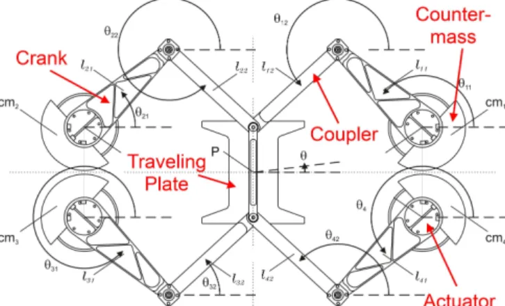
The Dual-V robot [15] is a 3-DOF planar RA-PKM developed within a collaboration between LIRMM laboratory (France) and the University of Twente (Netherlands). It belongs to the 4-RRR family in which, every RRR chain is composed of an actuator, a crank and a coupler (cf. Fig. 1). The manipulator’s links are made with aluminum and the arrangement of the four RRR chains allows one rotation and two translations of the end effector (a traveling plate).
B. Robot dynamic modeling
The displacements of the traveling plate of the robot are given with respect to a reference frame placed in the center its workspace. The operational coordinates of the center point of the traveling plate are described by the vector X “ rx, y, θsT P R3
where the pairpx, yq denotes the Cartesian position in the horizontal plane and θ denotes the rotation about the z-axis. The corresponding Cartesian velocities are expressed by the vector 9X“ r 9x, 9y, 9θsT
P R3
. The actuated joint coordinates are described by q“ rq1, q2, q3, q4sT P
R4
and the corresponding joints velocities are described by 9q “ r 9q1, 9q2, 9q3, 9q4sT P R4. One advantageous feature of the
Dual-V robot relies in having closed form analytic expres-sions for the forward and inverse kinematic problems [15]. Therefore, the transition from operational to joint spaces (and vice versa) is straightforward and does not require extensive numerical computations. The transformation from operational to joint velocities is achieved by means of the inverse Jacobian matrix Jmpqq P R4ˆ3 as follows
9q “ JmX.9 (1)
The input torques produced by the four actuators of the robot are described by Γ P R4
. To establish the inverse dynamic model of the Dual-V robot, the method proposed in [16] has been extended to include the rotational dynamics of the couplers. Actually, Dual-V differs from the well known Delta-like robots by having forearms (i.e. couplers) made with heavier material (i.e. Aluminum), therefore, their inertial dynamics cannot be neglected. Consequently, an
Fig. 1. Illustration of the CAD model of Dual-V robot
additional term is added to take into account these non negligible dynamics. In the sequel, we briefly introduce the inverse dynamic model of the robot and the necessary relationships for the subsequent developments.
For a prescribed motion of the traveling plate, the required input torques to move the different parts of the platform Γ can be divided into three components
Γ1` Γ2` Γ3“ Γ (2)
where Γi, i “ 1 . . . 3 is the required torque for moving a
different part of the mechanical structure. After computing each component Γi and rearranging the different terms, the
full inverse dynamic model of Dual-V robot can be expressed as follows pJT mq ˚ MIX: ` MIIp 9JmX9 ` JmX:q ` Γ3“ Γ (3) where p.q˚
denotes the pseudo-inverse of p.q and :X P R3
is the operational acceleration of the traveling plate. Γ3 “
fpX, 9X, :Xq P R4
is a highly nonlinear function that accounts for the required torques to compensate for the difference between the modeled and the real couplers inertia. MI P
R3ˆ3 is the mass matrix of the traveling plate including a part of the couplers and MII P R
4ˆ4
is the mass matrix of the cranks, the counter-masses and the a part of the couplers. The reader may refer to [15] for a more details.
III. BACKGROUND ONRISE FEEDBACKCONTROL SCHEME
Consider the dynamics of a n-DOFs kinematic manipulator in joint space [17]
Mpqq:q` Cpq, 9qq 9q ` Gpqq ` Γdptq “ Γptq (4)
where Mpqq P Rnˆn
is the inertia matrix, Cpq, 9qq P Rnˆn
the Coriolis and centrifugal forces matrix, Gpqq P Rn
the gravity force vector, Γdptq is a general nonlinear disturbance
standing for unmodeled phenomena (e.g. friction, external disturbances, etc) and Γptq P Rn
denotes the control input vector. It is worth noting that the dynamics (3) of the robot Dual-V can be put in the form (4) using the adequate kinematic relationships.
The RISE strategy is a continuous feedback control tech-nique that yields semi-global asymptotic tracking despite the presence of uncertainties in nonlinear systems [10]. This technique that features a unique integral signum term can accommodate for a large class of general uncertainties based on limited assumptions on the disturbance and the system to be controlled [12].
Assumption 1:The inertia matrix M is symmetric, positive definite and satisfies the following inequality@y P Rn
: m ¯kykď y T Mpqqy ď ¯mpqqkyk (5) where m
¯ is a known positive constant, ¯mpqq is a positive
function andk.k denotes the standard Euclidean norm.
Assumption 2:If qptq, 9qptq P L8 then the first and second
partial derivatives of the elements of Mpqq, Cpq, 9qq 9q and Gpqq with respect to qptq exist and are bounded.
Fig. 2. View of the experimental setup of Dual-V
Assumption 3: The nonlinear disturbance vector Γdptq
and its first two time derivatives are bounded (i.e. Γdptq, 9Γdptq, :Γdptq P L8).
To quantify the control objective, the tracking error e1ptq P
Rn and the filtered tracking error e2ptq P Rn are defined as
follows
e1“ qd´ q (6)
e2“ 9e1` α1e1, α1ą 0 (7)
where qdP Rn denotes the desired joint position. The RISE
feedback control action is defined by [10] ΓRISE“pks` 1qe2´ pks` 1qe2pt0q
` żt
t0
rpks` 1qα2e2pσq ` β sgnpe2pσqqs dσ
(8)
where ks, α2, β P R are positive constant gains and sgnpξq
is defined @ξ P Rn “ “ ξ1 ξ2 . . . ξn ‰ as sgnpξq fi “ sgnpξ1q sgnpξ2q . . . sgnpξnq ‰.
The tracking performance of the RISE controller can be further improved by adding a feedforward term based on the dynamics of the system (e.g. Neural Networks [13], model-based adaptive law as in [12] or known dynamics).
IV. PROPOSEDSOLUTION: A NOVELRISE-BASED ADAPTIVECONTROLLER
To improve the tracking performance of the RISE con-troller (8), we propose to extend it by adding an adaptive feedforward to compensate for linearly parametrized uncer-tainties. The motivation behind this strategy is to better track-ing performance and reduced control effort by accounttrack-ing for the structured uncertainties. Hence, the model-based adaptive feedforward term should compensate for some of the un-certainties while the RISE term should compensate for the remaining uncertainties which may yield to a reduced control effort and a better tracking of the reference trajectories.
To develop an adaptive controller, the system parameters in (4) have to be separated from the dynamic model [9]. Therefore, the following linear in the parameters reformula-tion can be obtained
1 2 3 4 5 6 7 8 r0, 0, 0sT r0.02, 0.04, 15sT r´0.02, 0.04, ´15sT r0.02, ´0.04, 15sT r´0.02, ´0.04, ´15sT x y
Fig. 3. Overview of one cycle of the desired trajectory to be performed by the Dual-V (units:rm, m, degsT
).
Mpqq:q` Cpq, 9qq 9q ` Gpqq “ Y pq, 9q, :qqΘ (9) where Y P Rnˆp
is known as the regression matrix and is formed by known nonlinear functions of q, 9q and :q, and ΘP Rpis the unknown parameters vector. This parameterization is primary in the development of any model-based adaptive controller. The proposed controller is the combination of the RISE feedback term (8) combined with a feedforward term based on (9). It is designed as follows
Γ“ ΓRISE` YdΘˆ (10)
where ΓRISE was introduced in (8), Ydfi Y pqd, 9qd, :qdq and
ˆ
Θptq is an estimate of Θ generated, as in [14], according to the following adaptation rule
d
dtΘptq “ KYˆ
T
d e2, Ką 0. (11) Remark: It is worth to note that the proposed controller in (10) seems to show similarities with the results in [12]. However, the adaptation law proposed in [12] is too compli-cated to be used in RA-PKMs since it involves the first and the second time derivatives of the regression matrix (which itself is a highly nonlinear function of q,9q and :q), especially with the unavoidable use of the pseudo-inverse of the inverse Jacobian matrix in the dynamic model of RA-PKMs (case of the Dual-V (3)).
For RA-PKMs, the control torques may contain antago-nistic forces that do not create any motion as they are in the null-space of JmT and can damage the mechanical structure
of the robot. Therefore, these dangerous internal forces need to be reduced. This can be achieved by projecting the input torques into the range space of JT
m[2] thanks to the following
projector
RJT
m “ I ´ NJmT (12)
where I P Rnˆn
is an identity matrix and NJT
m “ Inˆn´
pJT mq
˚
JT
0 10 20 30 40 −0.5 0 0.5 xe [mm] 0 10 20 30 40 −0.5 0 0.5 0 10 20 30 40 −1 0 1 ye [mm] 0 10 20 30 40 −1 0 1 0 10 20 30 40 −0.4 −0.2 0 0.2 θe [deg] Time [sec] 0 10 20 30 40 −0.4 −0.2 0 0.2 Time [sec]
Fig. 4. Scenario 1 - Cartesian tracking errors, left: RISE controller, right: RISE-based adaptive controller
results in RJT m “ pJ T mq ˚ JT
m Hence, the internal antagonistic
forces can be significantly reduced by projecting the control inputs given by (10) into the range space of JmT. This is
achieved by using the projection matrix RJT
m as follows Γ˚ “ RJT mpΓRISE` Yd ˆ Θq. (13)
V. EXPERIMENTALVALIDATION: APPLICATION ON THE DUAL-V RA-PKM
The experimental testbed used to implement the proposed controller is shown in Fig. 2. The Dual-V robot consists of four closed kinematic chains which are made with Alu-minum. The arms are mounted on four direct-drive actuators from ETEL Motion Technology. The actuators are fixed on an Aluminum base and can supply up to 127 N.m of input torques. Simulink and Real-Time Workshop (both from Mathworks Inc.) are used to implement and build the control algorithm as well as the trajectory generator. The generated code is then uploaded to the target PC, an industrial computer cadenced at 10 kHz and running xPC Target in real-time.
To evaluate the robustness of the proposed controller (13), two scenarios are considered. The first scenario deals with the nominal case where no uncertainties are introduced. In the second scenario, a payload is added on top of the traveling plate resulting in an additional unknown mass and inertia. The dynamic parameters of the Dual-V are divided into certain and uncertain parameters. The parameters of the couplers and the cranks are considered as certain ones while the only uncertain parameters are those of the traveling plate. This is a justifiable hypothesis since any payload will be handled by the traveling plate and hence, the uncertainty will only affect its dynamics. Consequently, the actual applied control torque is given by
Γ“ RJT
mpΓRISE` Y1dΘ1` Y2dΘˆ2q (14)
where the term Y1dΘ1 corresponds to the fixed dynamics
0 10 20 30 40 −5 0 5 τ1 [Nm] 0 10 20 30 40 −5 0 5 0 10 20 30 40 −5 0 5 τ2 [Nm] 0 10 20 30 40 −5 0 5 0 10 20 30 40 −5 0 5 τ3 [Nm] 0 10 20 30 40 −5 0 5 0 10 20 30 40 −5 0 5 τ4 [Nm] Time [sec] 0 10 20 30 40 −5 0 5 Time [sec]
Fig. 5. Scenario 1 - torque inputs, left: RISE controller, right: RISE-based adaptive controller.
(i.e. those of the cranks, the counter masses and part of the couplers) and is expressed as
Y1dΘ1“ MIIp 9Jmpqd, 9qdq 9Xd`Jmpqdq :Xdq`ΓpXd, 9Xd, :Xdq
(15) and Y2dΘˆ2 corresponds to the dynamics to be adapted
(i.e. those of the traveling plate and part of the couplers) expressed as
Y2dΘˆ2“ JmpqdqT ˚MˆIX:d (16)
where MˆI “ diagt ˆmtp, ˆmtp, ˆItpu is the unknown mass
matrix to be estimated. Hence, the regression matrix Y2 is
given by. Y2“ JmT ˚ » – : x 0 : y 0 0 θ: fi fl (17)
and the unknown parameters vector is ˆΘ2“
” ˆ mtp, ˆItp
ıT . In the experiments, the unknown parameters vector was initialized to zero (i.e ˆΘ2p0q “ r0, 0sT ). For comparison
purpose, the RISE feedback controller without the adaptive term is also implemented. From a theoretical point of view, the addition of a model-based feedforward yields better tracking results. Moreover, the control inputs should be reduced because some of the nonlinearities have already been compensated for by the model-based adaptive term.
The desired trajectories were generated in the Cartesian space using 5th order polynomials. The traveling plate of the robot has to move across different points through the workspace. The desired joint positions and velocities were obtained by solving the Inverse Kinematics problem and equation (1) respectively. Fig 3 illustrates a typical cycle of the traveling place displacements where the duration of each point-to-point trajectory is fixed to 0.8 seconds.
The standard midpoint algorithm was used to integrate the equation (11) and the joint velocities were estimated by
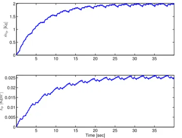
5 10 15 20 25 30 35 0 0.5 1 1.5 2 ˆmtp [K g] 5 10 15 20 25 30 35 0 0.005 0.01 0.015 0.02 0.025 ˆ Itp [K gm 2] Time [sec]
Fig. 6. Scenario 1 - Evolution of the estimated parameters versus time.
filtering of the measured joint positions (the Dual-V actuators are not equipped with velocity sensors). The control gains in (7), (8) for the RISE feedback and the adaptation gain in (11) that provided the best results were obtained by trial and error as follows
α1“ 40, ks“ 25.5, α2“ 124, β“ 75
K“ diagt75, 0.025u
In order to accurately evaluate the performance of both controllers, we introduce the following RMS-based criteria for the tracking errors
RM Sexy“ b RM S2 ex` RM S 2 ey (18)
where exfi xd´ x and ey fi yd´ y. We also evaluate the
RMS of the orientation error RMSeθ given eθ fi θd´ θ.
RM Sx is the standard Root Mean Square of the discrete
signal x of length k defined by RM Sx“ g f f e 1 k k ÿ i“1 xpiq2 . (19)
Regrading the energy consumption, the following torques based criterion is introduced
E“ n ÿ i“1 k ÿ j“1 |γipjq| (20)
where k is the number of samples and n is the number of actuators (e.g. n“ 4 in the case of the Dual-V)
TABLE I
SCENARIO1 -SUMMARY OF THE PERFORMANCE OF BOTH CONTROLLERS.
RISE Adaptive RISE Improvement RM Sexy [mm] 0.2515 0.1652 34.31 % RM Seθ [deg] 0.0708 0.0287 59.46 % E [Nm] 8.76ˆ 104 8.50ˆ 104 2.98 % 0 10 20 30 40 −0.5 0 0.5 xe [mm] 0 10 20 30 40 −0.5 0 0.5 0 10 20 30 40 −1 0 1 ye [mm] 0 10 20 30 40 −1 0 1 0 10 20 30 40 −0.4 −0.2 0 0.2 θe [deg] Time [sec] 0 10 20 30 40 −0.4 −0.2 0 0.2 Time [sec]
Fig. 7. Scenario 2 - Cartesian tracking errors, left: RISE controller, right: RISE-based adaptive controller.
Scenario 1: In this scenario, no additional mass is added to the mechanical structure (i.e. nominal case). The tracking errors are depicted in Fig 4. One can clearly notice that the addition of the adaptive feedforward term significantly reduces the tracking errors in all axes. The evolution of the unknown parameters estimates for the adaptive case are illustrated in Fig 6. The generated input control torques for both controllers are depicted in Fig 5. TABLE I summarizes the performance of both controllers in terms of Cartesian and joint tracking errors and power consumption. One can notice that the proposed adaptive controller yields much better tracking performance both in Cartesian and joint spaces while consuming slightly less energy.
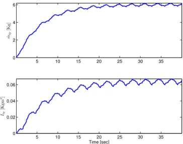
Scenario 2: In this scenario, an additional unknown weight is added on top of the traveling plate. The main motivation of experiencing this scenario is to firstly evaluate the robustness of the proposed controller to load changes. Then, to compare once again the RISE and adaptive RISE based controllers in terms of tracking accuracy and energy consumption. The Cartesian tracking errors are depicted in Fig 7. It can be noticed that the proposed adaptive controller yields better tracking performance and the improvement is more notice-able than the nominal case. TABLE II summarizes the RMS errors of both controllers as well as the energy consumption. The evolution of the new estimated parameters due to the additional weight is illustrated in Fig 9. One can see that the parameters converge to new values different from those in the nominal case due to the unknown added weight. The
TABLE II
SCENARIO2 -SUMMARY OF THE PERFORMANCE OF BOTH CONTROLLERS.
RISE Adaptive RISE Improvement RM Sexy [mm] 0.4145 0.1965 52.59 %
RM Seθ [deg] 0.1247 0.0592 52.52 %
0 10 20 30 40 −5 0 5 τ1 [Nm] 0 10 20 30 40 −5 0 5 0 10 20 30 40 −5 0 5 τ2 [Nm] 0 10 20 30 40 −5 0 5 0 10 20 30 40 −5 0 5 τ3 [Nm] 0 10 20 30 40 −5 0 5 0 10 20 30 40 −5 0 5 τ4 [Nm] Time [sec] 0 10 20 30 40 −5 0 5 Time [sec]
Fig. 8. Scenario 2 - torque inputs, left: RISE controller, right: RISE-based adaptive controller.
input torques are depicted in Fig 5. Final conclusions can be therefore drawn that the proposed controller provides better tracking results while consuming slightly lower power.
Results can be viewed in the video available at the following url: http://youtu.be/VN5hJAG5JQE.
VI. CONCLUSIONS& FUTUREWORK
A novel RISE-based adaptive controller that combines the RISE feedback and a model-based feedforward adaptive term is developed. The RISE feedback strategy is known for its semi-global stability despite the presence of general nonlin-ear unstructured disturbances based on limited assumptions about the system. To improve the tracking performance of the RISE control strategy, an additional adaptive model-based term is added. The adaptive feedforward term includes some knowledge about the system dynamics and allows to compensate for the structured uncertainties. With the amal-gamation of the RISE and the adaptive feedforward terms, the tracking errors and the control effort are significantly reduced compared to the basic RISE controller. The proposed control solution as well as the classical RISE controller were experimentally implemented and evaluated on a real RA-PKM to consolidate the theoretical development. The results clearly demonstrate the relevance of the proposed approach. This work can be further extended and improved by taking into account more unknown parameters and by using a projection method for the adaption law including known bounds of the parameters.
REFERENCES
[1] J. P. Merlet, Parallel Robots, Second Edition. Dordrecht, Netherlands: Springer, 2006.
[2] A. M ˜AŒller, “Effects of geometric imperfections to the control of re-dundantly actuated parallel manipulators,” in Proc. IEEE International
Conference on Robotics and Automation (ICRA’09), Kobe, Japan, May
2009, pp. 1782–1787.
[3] F. Paccot, N. Andreff, and P. Martinet, “A review on the dynamic control of parallel kinematic machines: Theory and experiments,” The
International Journal of Robotics Research, vol. 28, no. 3, pp. 395–
416, Mar. 2009. 5 10 15 20 25 30 35 0 2 4 6 ˆmtp [K g] 5 10 15 20 25 30 35 0 0.02 0.04 0.06 ˆ Itp [K gm 2] Time [sec]
Fig. 9. Scenario 2 - Evolution of the estimated parameters versus time.
[4] F. L.Lewis, D. M.Dawson, and C. T.Abdallah, Robot Manipulator
Control, Theory and Practice. New York, USA: Marcel Dekker,
Inc., 2004.
[5] P. R. Ouyang, W. Zhang, and F. Wu, “Nonlinear pd control for trajectory tracking with consideration of the design for control method-ology,” in Proc. IEEE International Conference on Robotics and
Automation (ICRA’02), Washington, USA, May 2002, pp. 4126–4131.
[6] J. Luh, M. Walker, and R. Paul, “Resolved-acceleration control of mechanical manipulators,” IEEE Trans. Automat. Contr., vol. 25, no. 3, pp. 468–474, June 1980.
[7] D. Koditschek, “Natural motion for robot arms,” in Proc. The 23rd
IEEE Conference on Decision and Control (CDC’84), Las Vegas,
Nevada, USA, Dec. 1984, pp. 733–735.
[8] J. F. He, H. Z. Jiang, D. C. Cong, Z. M. Ye, and J. W. Han, “A survey on control of parallel manipulator,” Key Engineering Materials, vol. 339, pp. 307–313, May 2007.
[9] J. J. Craig, P. Hsu, and S. S. Sastry, “Adaptive control of mechanical manipulators,” The International Journal of Robotics Research, vol. 6, no. 2, pp. 16–28, June 1987.
[10] B. Xian, D. M. Dawson, M. S. D. Queiroz, and J. Chen, “A con-tinuous asymptotic tracking control strategy for uncertain multi-input nonlinear systems,” IEEE Trans. Automat. Contr., vol. 49, no. 7, pp. 1206–1211, July 2004.
[11] N. Fischer, S. Bhasin, and W. Dixon, “Nonlinear control of an autonomous underwater vehicle: A rise-based approach,” in Proc.
IEEE American Control Conference (ACC’11), San Francisco, USA,
June 2011, pp. 3972–3977.
[12] P. M. Patre, W. MacKunis, C. Makkar, and W. E. Dixon, “Dynamics and control of redundantly actuated parallel manipulators,” IEEE
Trans. Contr. Syst. Technol., vol. 16, no. 2, pp. 473–379, Mar. 2008.
[13] P. M. Patre, W. MacKunis, K. Kaiser, and W. E. Dixon, “Asymptotic tracking for uncertain dynamic systems via a multilayer neural net-work feedforward and rise feedback control structure,” IEEE Trans.
Automat. Contr., vol. 53, no. 9, pp. 2180–2185, Oct. 2008.
[14] N. Sadegh and R. Horowitz, “Stability and robustness analysis of a class of adaptive controllers for robotic manipulators,” The
Interna-tional Journal of Robotics Research, vol. 9, no. 3, pp. 74–92, June
1990.
[15] V. van der Wijk, S. Krut, F. Pierrot, and J. L. Herder, “Design and experimental evaluation of a dynamically balanced redundant planar 4-rrr parallel manipulator,” The International Journal of Robotics
Research, vol. 32, no. 6, pp. 744–759, May 2013.
[16] D. Corbel, M. Gouttefarde, and O. Company, “Asymptotic tracking for systems with structured and unstructured uncertainties,” in Proc. IEEE
International Conference on Robotics and Automation (ICRA’10),
Anchorage, Alaska, May 2010, pp. 4675–4682.
[17] H. Cheng, Y.-K. Yiu, and Z. Li, “Dynamics and control of redundantly actuated parallel manipulators,” IEEE/ASME Trans. Mechatron., vol. 8, no. 4, pp. 483–491, Dec. 2003.