HAL Id: hal-00845292
https://hal.archives-ouvertes.fr/hal-00845292
Submitted on 16 Jul 2013
HAL is a multi-disciplinary open access
archive for the deposit and dissemination of
sci-entific research documents, whether they are
pub-lished or not. The documents may come from
teaching and research institutions in France or
abroad, or from public or private research centers.
L’archive ouverte pluridisciplinaire HAL, est
destinée au dépôt et à la diffusion de documents
scientifiques de niveau recherche, publiés ou non,
émanant des établissements d’enseignement et de
recherche français ou étrangers, des laboratoires
publics ou privés.
Electrical Aging of the Insulation of Low Voltage
Machines: Model definition and test with the Design of
Experiments
Nadine Lahoud, Jérôme Faucher, David Malec, Pascal Maussion
To cite this version:
Nadine Lahoud, Jérôme Faucher, David Malec, Pascal Maussion. Electrical Aging of the Insulation of
Low Voltage Machines: Model definition and test with the Design of Experiments. IEEE Transactions
on Industrial Electronics, Institute of Electrical and Electronics Engineers, 2013, vol. 60, pp.4147-4155.
�10.1109/TIE.2013.2245615�. �hal-00845292�
This is an author-deposited version published in :
http://oatao.univ-toulouse.fr/
Eprints ID : 9210
To link to this article : DOI:
10.1109/TIE.2013.2245615
URL :
http://dx.doi.org/10.1109/TIE.2013.2245615
O
pen
A
rchive
T
OULOUSE
A
rchive
O
uverte (
OATAO
)
OATAO is an open access repository that collects the work of Toulouse researchers and
makes it freely available over the web where possible.
To cite this version :
Lahoud , Nadine and Faucher, Jérôme and Malec, David
and
Maussion, Pascal
Electrical Aging of the Insulation of Low Voltage
Machines: Model definition and test with the Design of
Experiments.
(2013) IEEE Transactions on Industrial Electronics,
vol. 60 (n° 9). pp. 4147-4155. ISSN 0278-0046
Any correspondence concerning this service should be sent to the repository
administrator:
staff-oatao@listes.diff.inp-toulouse.fr
Electrical Aging of the Insulation of Low Voltage
Machines: Model definition and test with the Design
of Experiments
Nadine Lahoud, Jérôme Faucher, David Malec, Pascal Maussion, Member IEEE
1
Abstract— The aim of this paper is to present a method for modeling
the lifespan of insulation materials in a partial discharge regime. Based on the design of experiments, it has many advantages: it reduces the number of time-consuming experiments, increases the accuracy of the results and allows lifespan modeling under various stress conditions including coupling effects between the factors. Accelerated aging tests are carried out to determine the lifespan of these materials. The resulting model presents an original relationship between the logarithm of the insulation lifespan and that of electrically applied stress and an exponential form of the temperature. Results show that the most influential factors can be identified according to their effects on the insulation lifespan. Moreover, the lifespan model validity is tested either with additional points which have not been used for modeling or through statistical tests. Finally, it is shown that fractional plans are not suitable to reduce the number of experiments. This application of the experimental design is best used during the initial phase, before the final drive has been built and any on-line diagnostic.
Index terms—Diagnosis, dielectrics, insulation, insulation testing, accelerated aging, lifespan estimation, condition monitoring, modeling, aging.
NOMENCLATURE
E
i Effect of factor no. iE
ij Effect of interaction between factor no. i and factor no. jy
i Experimental value, measured at experiment no. iF
i Level of factor no. i, could be +1, -1 or any value between -1 and +1M
Average experimental valueL
Lifespan in minutesT
Temperature in °C V Voltage in V F Frequency in Hz W ai n N pShapiro-Wilk statistic parameter Shapiro-Wilk coefficient Number of experiments
Number of samples = number of repetitions Probability risk
The authors are with Université de Toulouse; INPT, UPS; LAPLACE; ENSEEIHT, CNRS ; F-31071 Toulouse, France. (phone : +33534322364; fax: +33561638875, e-mail : maussion@laplace.univ-tlse.fr)
I. INTRODUCTION
With the increasing use of electrics in aircraft, the reliability of the low voltage insulation systems in rotating machines has become a very important issue. Many papers, in particular [1], have reported that stator-winding insulation is one of the weakest components in a drive (around 40% of failures). In this domain, condition monitoring and early detection of incipient faults can reduce maintenance and increase reliability.
According to the diagnosis method classification presented in [2], diagnosis of the insulation systems or materials can be model-based, signal-based or data-based. Various testing and monitoring model-based or signal-based methods have been developed to check the stator insulation system conditions in electric motors. A comprehensive review of the testing and monitoring methods is presented in [3] with online and offline methods capable of diagnosing the condition of the turn-to-turn insulation in low-voltage machines. Furthermore, a wide range of diagnosis techniques is reviewed in [4] for online stator inter-turn fault detection and diagnosis in PMSM. Motor current signature analysis, harmonic analysis in the a b reference frame, high frequency
current injection, artificial intelligence-based methods and models for inter-turn fault simulation are presented.
An alternative way to manage the insulation system condition in electrical machines consists in studying the numerous factors which could affect their lifespan. Operating conditions and material design are involved in this aging process and interact with each other. Full aging tests for all the factors around the nominal conditions could be time consuming. Consequently, accelerated aging tests are usually performed in order to study and predict the lifespan. This kind of test can be used for different objects in electrical engineering such as IGBT modules [5] in high temperature power cycling or nano-structured enamels on twisted pairs [6]. These tests are used to obtain failure statistics. This data may determine a functional relationship between one or more applied stresses (electrical, thermal, mechanical, etc.) and either a potential damage incurred or the characteristic insulation lifespan. Combining the different stresses quoted earlier could have a dramatic effect on both bearings and stator winding insulation [7]. As an example, [6] points out the behavior under severe waveforms of three different insulating organic enamels on twisted pairs, subjected to electrical degradation due to breakdown voltage tests. The conclusion is that the PEI enamel with nano-sized silica is
better with respect to the other tested materials but does not give any lifespan model.
Data processing of test results can also generate lifespan models. Reference [8] estimates the effect of electro-thermal aging in the lifespan estimation of hydroelectric generator stator windings. It provides lifespan plots but only concerning one factor: the winding temperature. Over the last few decades, several models have been proposed for electrical insulation life-end modeling [9-10] with respect to the physical, thermal and electro-mechanical aspects of the electrical aging process. Despite these studies, this phenomenon remains complex and difficult to understand, to forecast and finally to model, especially in PWM inverters. It is well known that the insulation degradation rate in rotating machines can be greatly affected by many operating factors such as voltage, frequency, temperature, pressure, etc. and these stresses can synergize. Nevertheless, there is no comprehensive model for insulation lifespan prediction. The proposed models of degradation or of lifespan differ slightly from one paper to another but they are all based on physics and include some factors which are specific to the material or the aging mechanism.
Moreover, the choice of the lifespan forms remains critical for model accuracy. Various forms can be found in different works [11-12] but they mainly involve a log-based relationship for frequency and voltage and an exponential form for the temperature. In this paper, the “Design of Experiments” (DoE) is used to define and to validate a theoretical lifespan model. Taguchi’s method, which was developed in Japan by G. Taguchi to improve the implementation of total quality control is the best-known. It is based on the design of experiments to provide almost optimal quality characteristics for a specific objective. This method is applied to accelerated tests on polyesterimide films which are widely used in insulation systems in order to establish an insulation lifespan model. It takes into account logarithmic and exponential forms of the different stress factors; these forms are chosen with respect to previous theoretical studies and some experimental results. Thus, DoE is presented followed by its application to accelerated aging test results to obtain a mathematical lifespan model focused essentially on the most influential factors [13]. One advantage of the method is that this new kind of model includes some non-linear relationships between the stress variables because of the interactions between the stress factors. This can be considered as a new type of model-based method, an original way to a-priori choose a model and to carry out just the required number of accelerated tests in order to compute the model parameters. However, a model without validation tests is not complete and presents only half of the work. Consequently, this paper investigates the statistical analysis that should be carried out to test which parameters are significant or not. Moreover, the model validity will be tested on additional experimental points which have not been used for the identification of its coefficients.
The final objective of this work is to extend the validity domain of the model, primarily towards low constraint levels, for prognostic purposes. The prognostication of residual life has been less intensely explored than diagnosis. Recent works, [14-16] propose investigations for different
applications. In [14], a mathematical method for the interrogation of the system state under cyclic thermo-mechanical stresses has been proposed for different lead-free solder alloy systems. They are based on the derivation of damage proxies and prior-damage-based nonlinear identification algorithms. In [16], adaptive neuro-fuzzy inference systems and hidden Markov estimators give the opportunity to develop a new prognostic method. Vibration signals are used to compute 2 or 4 step-ahead condition monitoring indexes which are successfully compared to measurements. It is applied to mechanical faults in helicopters such as cracks on a planetary gear carrier plate and bearing faults. Also using hidden Markov models, [15] presents a prognosis method for the gear faults in dc machines, based on the time–frequency features extracted from the motor current. They are considered as machine health indicators which can predict the severity of a future fault. The paper focuses on methods for computing the parameters from limited data since previously compiled data is not available.
II. THE DESIGN OF EXPERIMENT METHOD
In the lifespan modeling of insulation systems as well as in many other complex and/or non linear domains, there is no general method to reach optimal design or to indentify a model, given specific requirements, except varying the parameters step by step. This strategy, called One Factor At a Time (OFAT) method, can be time-consuming if a comprehensive series of experiments is conducted. Moreover, it is valid only when no coupling effects exist between the factors. The design of experiments is a systematic and efficient method to determine the best combination of factor levels in an optimization process or to define a model of the system response and to identify its coefficients. The advantages are the following:
1) the reduction in the number of experiments to obtain the optimal solution,
2) an increase in the accuracy of the results, assuming an isovariance for each of the n experiments, the variance for each factor will be divided by n1/2,
3) the possibility of considering several factors in the same experimental plan (instead of OFAT) and to take into account interactions between factors,
4) a statistical analysis can be carried out at the end of the method in order to check if the factor effects or the model coefficients are statistically significant or not. A statistical hypothesis test is used to make decisions. Experimental design started during the 1930s in England with M. Fisher’s work [17] and has been particularly developed since the publication of some predefined tables by Taguchi. The principle of this methodology is to implement a schedule of experiments designed to obtain the most accurate information for a specific problem with a minimum number of experiments. Its performance has been proved in different areas of application, especially in chemistry and mechanics, where a high volume of parameters have to be simultaneously optimized. In recent years, they have been successfully used in electrical engineering for electrical machine design (induction, reluctance, synchronous…) or to improve their performance and optimize their design [18-23]. Applications of the DoE can also be found in the control of power electronic devices
[24-26], to increase the reliability in inverters for photovoltaic systems [27] or to find optimal rapid-charging patterns for LiIon batteries [28].
Full factorial designs involve implementing a set of experiments in which all relevant parameters, called factors, are systematically varied. The number of values each parameter will carry has to be set thereby fixing the levels of the controlling factors. The main purpose is to obtain information on the effects of the selected parameters. The idea is to modify the level of each factor in every experiment according to a specific procedure. This allows a drastic reduction in the number of required experiments. A simple example with only two levels is presented in Table I, where centered reduced variables are used, i.e. (-1) for the low level and (+1) for the high level of each factor.
TABLE I
EXAMPLE OF AN EXPERIMENTAL TABLE
Experiment number M Factor 1 Factor 2 Interaction 12 Criterion Y 1 1 -1 -1 +1 y1 2 1 +1 -1 -1 y2 3 1 -1 +1 -1 y3 4 1 +1 +1 +1 y4 M
Each line represents an experiment and each column is indexed to a factor. For each experiment (i), the selected criterion value (yi), which is the system response, is measured. In the design of experiments, the effect of a factor is obtained according to expression (1). For example, E1 = 0.12 means that Factor 1 at the highest level has an effect of +0.12 on the criterion with respect to the average value of the criterion, named M. Moreover, a key feature of the DoE is that the effect of interactions between factors 1 and 2 for example, can also be determined. Equation (2) presents the average effect of interaction E12 between factors 1 and 2 on the desired criterion.
4 4 3 2 1 1 y y y y E + -+ -= (1) 4 4 3 2 1 12 y y y y E + -= (2)
Consequently, the mathematical model relating response Y to the different factors is as follows (3):
Y ~ M + E1.F1 + E2.F2 + E12.IF1F2 (3) where :
· Y is the system response vector which, in this case, represents the insulation lifespans,
· M is the mean value for all aging test responses, · Fi are the factor levels affecting the aging process, · IFiFj are the levels of the interactions between factors
Fi and Fj,
· Ei are the effects of the factors and Eij the effects of the interactions between factors Fi and Fj on the global response.
Furthermore, it is easy to verify that the effect vector (Ê) can be calculated through the following relationship:
Ê = X-1.Y (4) with
÷
÷
÷
÷
ø
ö
ç
ç
ç
ç
è
æ
= 2 . 1 2 1 ˆ E E E M E (5)where Ê is the vector of the different factor effects on the criterion and the corresponding interactions between them. X is the matrix obtained from the experimental plan as shown in the shadowed part of Table I and Y is the vector of the experimental result values presented in the last column.
In the domain of electrical insulation degradation, the DoE has already been used for tracking the influential operating parameters on the insulation lifespan of kapton films [29] and for degradation analysis in terms of a better understanding of a reliable water-treeing test [30]. In this paper the DoE is used to analyze the aging process of organic rotating machine insulation in partial discharge regime. The input variables are, in this case, the parameters affecting the insulation degradation and the process output is the insulation lifespan. These designs include all combinations of every factor level and the number of experiments depends on the number of factor levels. These designs are usually noted Xk, i.e. the corresponding experiment table is composed of k factors with
X levels each.
III. ACCELERATED AGING TESTS A. Materials
One of the aims of this study is to verify the capacity of the DoE to establish an electrical lifespan model for the insulation materials of rotating machines fed by inverters. Consequently, accelerated aging tests are performed in order to relate the applied external stresses (factors) to the insulation lifespan (response). As stated in the introduction, this study concerns only the secondary part (which consists of the impregnation varnish) of an inverter-fed rotating machine insulation system (composed of impregnation varnish and enameled wires). It is common knowledge that partial discharges occur in rotating machines fed by inverters [6] [31-33]. The impregnation varnish is the first element of the insulation system to be in contact with partial discharges and becomes the most affected part. Failure often occurs at this level in the insulation system. Rotating machine insulation is often made of polyesterimide (PEI) which is an organic material. In this study, a simple structure in the form of steel plates coated with polyesterimide (PEI - thermal class: 180°C), as shown in Fig. 1, was subjected to accelerated aging under different external stress conditions. The plate is 15cm x 9cm with a 90µm coating. Coated steel plates with a well-controlled insulation thickness were preferred to twisted pairs in this study. Even though the final objective is to test stators, films are a good starting point to test the design of experiment capacity for lifespan modeling. Twisted pairs have already
been studied in [29] for sinusoidal stress voltage and they will be tested in future works before the stators.
Fig. 1. Tested 90µm coated steel plate (15cm x 9cm) .
For each test condition, the sample lifespan (i.e. when insulation properties fail or exceed the design limits) was measured. When a sample breaks down, the over-current is immediately detected by the HV-switch and the sample is switched off while the other samples remain supplied. Eight samples were simultaneously tested under each experimental condition. Lifespan data in this paper is presented according to Weibull’s statistical processing [34], which is commonly used for breakdown data treatment and sometimes in terms of average lifespan for comparison.
B. Applied stresses
The failure process is driven by several stresses acting simultaneously such as electrical, thermal, mechanical and ambient stresses. These different stresses can affect the insulation degradation phenomenon in rotating machines even during normal service conditions, especially when fed by inverters. Additional stresses could be moisture, aggressive chemicals, dirt, radiation, etc. In inverter-fed rotating machines, over-voltages occur at the motor terminals and the voltage distribution in the winding is not homogeneous just after voltage application. These over-voltages can lead to partial discharges occurring between phases, between turns or between turns and ground. Nevertheless, it is obvious that an increase in the rate of voltage rise/fall and switching frequency has a decreasing effect on machine reliability. Reference [7] presents the development of new techniques for the quality assessment of stator winding insulation. The objective is a reliable operation of inverter-fed machines. They are based on offline tests (capacitance, dissipation factor, and/or insulation resistance), using the inverter to apply different voltage tests to the motor. The purpose of our study is to provide information on the insulation material during the design phase. The experimental aging conditions were therefore chosen to ensure that the insulation degradation is mainly due to the partial discharges. However, for simplicity and because of their influence, only three major parameters were studied:
1) the square wave applied HVDC (V), 2) the frequency of the applied voltage (F), 3) temperature (T).
Depending on the results of this work, other factors such as pressure and humidity could be studied in future work.
C. The experimental setup
The samples were tested in our experimental setup, shown in Fig.2, which is fully described in [13]. Under electrical
stress, the steel plate acts as one electrode and a spherical stainless steel electrode (diameter: 1mm) is a second. The only pressure applied by the spherical electrodes on the sample was due to their mass (0.8g); no additional springs were used. Samples were placed in a climatic chamber where the temperature is fully controlled. The lifespan of each sample was measured using a timer (one per sample) which stopped counting as soon as the current increased and crossed a threshold at which the corresponding sample broke down. The faulty specimen was disconnected while the survivors remained under voltage and at the controlled temperature.
Fig. 2. The experimental setup for accelerated aging tests, climatic chambers and power electronic.
IV. APPLICATION TO THE INSULATION AGING MODEL
The traditional methodology for an experimental design consists of 4 steps: study preparation including choice of the response and factor forms - which is the main scope of this paper - and the determination of factor levels, choice of the experimental design, the experiment itself and the result analysis and discussion
A. Step 1: Study preparation
1) Choice of the response and factor forms
In this approach, the description of the insulation degradation in a partial discharge regime is taken into consideration. In this specific case, the effect of the electrical stress level on the insulation lifespan is most often represented by the inverse power model [35],such as in (6):
L = c. E—n (6)
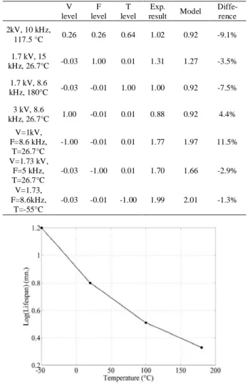
where L is the insulation lifespan, E is the electrical field, c is a material constant and n is called the power law constant. Our experimental results have shown that the lifespan evolution (for a given temperature and frequency) complies with this relationship [36]. Moreover, under electro-thermal stress, our experimental results presented in Fig.3 and in other state –of- the-art works [35-36], have shown that the variation in the insulation lifespan with the applied temperature, at a fixed voltage and frequency, may follow (7):
Log(L) = a.exp(-b.T) (7)
L is the insulation lifespan, T is the applied temperature
and a and b are material constants. This assumption will be used in our model henceforth. Constants a and b are calculated from lifespan experimental results under electro-thermal stress and obtained by drawing in Fig. 3, the
variation of the insulation lifespan logarithm with respect to the temperature (for V=2kV and F=10 kHz i.e. at the center of the experimental domain). Their exact values are calculated with expression (7) from these experimental results as shown in [45] and leads to a=0.87 and b=5.64x10⁻³.
Fig 3. Effect of temperature on insulation lifespan, from -55°C to 180°C, for V=2kV and F =10 kHz
This model presents a logarithmic form of electrical stress (i.e. voltage and frequency) and an exponential form of the temperature according to (6) and (7). Consequently, the corresponding model can be expressed in (8):
Log(L) ~ M + EV.log(V) + EF.log(F) + ET.exp(-bT) +
EFV.log(V).log(F) + EVT.log(V).exp(-bT) +
EFT.log(F).exp(-bT) + EVFT.log(V).log(F).exp(-bT) (8)
2) The determination of factor levels
As already stated, three factors were chosen, voltage, frequency and temperature, at levels as follows:
1) The extreme values of the applied voltage (square wave bipolar with 50% duty cycle) were ±1 kV and ±3 kV. The lower value corresponds to a possible overvoltage in normal service conditions. By considering a 500 VDC bus voltage (or +/-270V) and a complete impedance mismatch between the motor and its feeding cable, depending on the distance between the first turn of different phases and the last, the voltage stress between them can rise up to 1 kV. The highest value was chosen to accelerate the aging tests.
2) The frequency values range from 5 kHz to 15 kHz, which are considered as normal PWM frequencies in these aeronautical applications.
3) The temperature values range from -55°C to 180°C (thermal class of the insulating material) and were also chosen so as to accelerate the aging tests.
Table II presents the chosen factors with their corresponding forms. Table III gives all the 23 (3 factors, 2 levels each) possible combinations between the different factor levels. This experimental plan was carried out and the corresponding sample lifespans are listed (in minutes).
TABLEII
LEVELS OF THE THREE STRESS FACTORS
Factors Level (-1) Level (+1) Level (0)
Log (Voltage (kV)) Log(1) Log(3) Log(1.73)
Log((Frequency (kHz)) Log(5) Log(15) Log(8.7)
Exp(-b.Temperature (°C)) Exp(55b) Exp(-180b) Exp(26.7b)
TABLE III
EXPERIMENTAL RESULTS WITH THREE FACTORS AT 2 LEVELS EACH :8 EXPERIMENTS WITH 8 SAMPLES EACH
Log(V) Log(F) e(-bT) Lifespan (minutes)
Test n° F1 F2 F3 Sample no. 1 Sample no. 2 Sample no. 3 Sample no. 4 Sample no. 5 Sample no. 6 Sample no. 7 Sample no. 8 1 -1 -1 -1 378 418 568 587 634 642 786 850 2 -1 -1 1 25 29 23 29 26 30 24 31 3 -1 1 -1 169 187 268 268 343 364 162 322 4 -1 1 1 14,5 14,25 13,4 13,8 14,8 15 13 15,5 5 1 -1 -1 26 30 28 33 24 29 28 35 6 1 -1 1 6 6,5 6,2 6,8 5,5 6,5 6 6,3 7 1 1 -1 14 16,21 15,07 15,5 15,28 16 12,5 14,8 8 1 1 1 2,2 2,233 1,133 1,65 2,033 1,516 0,933 1,4 TABLE IV
FULL FACTORIAL DESIGN MATRIX FOR THREE FACTORS WITH 2 LEVELS EACH
Log(V) Log(F) e(-bT) Log(V).Log(F) Log(V).e(-bT) Log(F). e(-bT) Log(V).Log(F)
.e(-bT) Log(L)
Test n° M F1 F2 F3 I(V.F) I(V.T) I(F.T) I(V.F.T) Weibull Average
1 1 -1 -1 -1 1 1 1 -1 2.822 2.769 2 1 -1 -1 1 1 -1 -1 1 1.452 1.431 3 1 -1 1 -1 -1 1 -1 1 2.457 2.396 4 1 -1 1 1 -1 -1 1 -1 1.165 1.154 5 1 1 -1 -1 -1 -1 1 1 1.485 1.461 6 1 1 -1 1 -1 1 -1 -1 0.805 0.793 7 1 1 1 -1 1 -1 -1 -1 1.187 1.172 8 1 1 1 1 1 1 1 1 0.2 0.196
Tests at the center of the study domain
Model : Log(L)=f[Log(V), Log(F) and exp(-b.T)]
B. Steps 2 and 3: Choice of the experimental design and experimentation
Table IV gives the 23 possible combinations between the different factor levels and their interactions. The shadowed columns give the Weibull treatment and the average values of the eight samples simultaneously tested under each experimental condition. The Weibull statistical process is commonly used for breakdown analysis. One can note that test N°9 represents the experiments at the center of the study domain (level 0), as shown in Table II. This test is run for model validation to compare the predicted lifespan and the experimental value at the center of the experimental domain.
C. Step 4: Result Analysis
This method demonstrates the effects of the different factors and interactions on the sample lifespan.
1) The factors and interaction effect values
The different effects are calculated by applying equation (4) to the experimental domain and the response matrices presented in Table IV. The different effect values are presented in Table V and in diagram form in Fig. 4.
TABLEV
EFFECT VALUES FOR THE LIFESPAN MODEL
Model Effect M 1.45 Log(V) -0.53 Log(F) -0.19 Exp(-bT) -0.54 ILog(V).Log(F) -0.03 ILog(V).exp(-bT) 0.12 ILog(F). exp(-bT) -0.03 ILog(F).Log(F). exp(-bT) -0.05
This diagram clearly shows the effect of each factor with respect to the average (M) and the following conclusions:
1) the three factors (i.e. voltage, frequency and temperature) have a decreasing effect on the insulation lifespan,
2) the voltage and the temperature effects are more significant than the frequency effect,
3) the most influential factors (i.e. voltage and temperature) have the highest interaction.
2) The mathematical model analysis
In order to obtain a mathematical form for the model, the different effects of (8) must be replaced by their corresponding values given in Table V. This model presents the variation of the lifespan logarithm with respect to a logarithmic form of the electrical stress and an exponential form of the temperature, as expressed in (9).
Log(L) ~ 1.45 - 0.53.log(V) - 0.19.log(F) - 0.54.exp(-bT) - 0.03.log(V).log(F) + 0.12.log(V).exp(-bT)
- 0.03.log(F).exp(bT) - 0.05.log(V).log(F).exp(-bT) (9)
Fig. 4. The diagram effects for the model (from left to right), M is the average lifespan while the other terms are the stress effects; results are in the same order as in Table V i.e. first M, then log(V), etc.
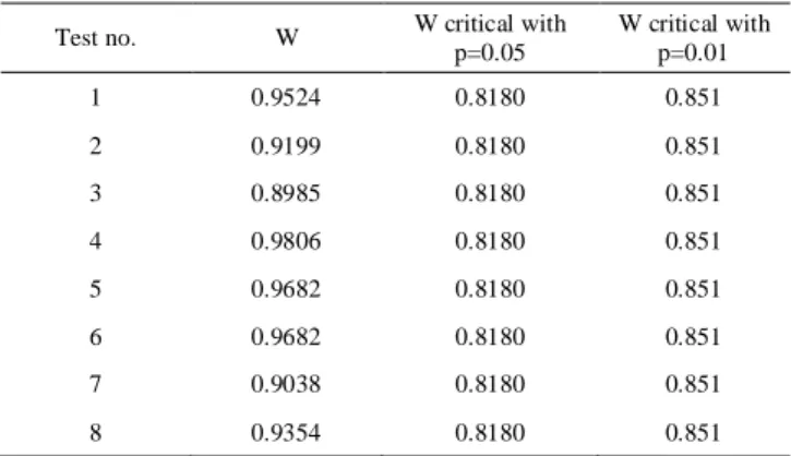
From this model, statistical analyses should be carried out in order to test which factors are significant. Most of the statistical tests are based on the assumption that the samples come from a normally distributed population. This was verified in this paper through the Shapiro–Wilk test [37-38] for each line of the experimental plan in Table III. The test statistic W is given by expression (10), where xi is the lifespan measured in each sample no. i, xthe average value on each line and ai is the Shapiro-Wilk coefficient which can be read in a dedicated table. The normality assumption is accepted with a risk p if W is greater than a critical W which depends on the number of samples and on the risk probability p. Table VI shows that the calculated W is always greater than the critical W, then the 8 different populations can be considered as normally distributed.
å
å
= = = = = = -= 8 1 2 8 1 2 ) ( ) . (w
i n i i n i i i i x x x a (10)The normal distribution assumption can also be tested with a normal probability plot [39] in Fig. 5, with the ordered response values for experiment no. 8 from Table III (for example) on the vertical axis and the normal order statistical medians on the horizontal axis. The normality assumption is accepted because the points on this plot form an almost perfect linear pattern.
TABLEVI
WSHAPIRO-WILK PARAMETER COMPARED TO THE CRITICAL W WITH N=8
SAMPLES AND DIFFERENT RISK PROBABILITIES
Test no. W W critical with
p=0.05 W critical with p=0.01 1 0.9524 0.8180 0.851 2 0.9199 0.8180 0.851 3 0.8985 0.8180 0.851 4 0.9806 0.8180 0.851 5 0.9682 0.8180 0.851 6 0.9682 0.8180 0.851 7 0.9038 0.8180 0.851 8 0.9354 0.8180 0.851
Fig. 5. Normal probability plot, with the ordered response values on the vertical axis and the normal order statistical medians on the horizontal axis for experiment no. 8 in TABLE III.
A major difficulty is the determination of experimental error. The estimation accuracy s of the experimental standard deviation on the criterion σy, depends on the number of experiments. By repeating N times each experiment of the design table, the estimation si for each experiment is improved. yi,j is the jth repetition of the ith experiment (among n) and _
i
y is the average of the N repetitions of the ith
experiment. The variance is given by equation (11).
2 1 _ , 2
1
1
å
=÷
ø
ö
ç
è
æ
-=
N j i j i iy
y
N
s
(11) Based on the classical isovariance assumption, equation (11) can be written and, as a consequence, the estimation of the experimental standard deviation on the effect sE, can be expressed in (12). This expression shows that the precision is increased since the standard variation is divided by the square root of the number of experiments n.
n
s
s
E=
(12)n
s
s
s
n i i iå
==
=
1 2 _ 2 (13)The confidence interval is thus balanced by the Student’s variable
t
an.(N-1) at n.(N-1) degrees of freedom with the probability α to be exceeded in absolute value. Then, the confidence interval for a probability α isE N n
s
t
´
±
.( - )1a around the average effect value. By repeating the 8 experiments of the Hadamard experimental design 8 times and defining a 99% probability, the confidence interval is 0.083. According to effect values given by Table V, the final expression of Log(L) (14), using only the most significant factors, can be re-written:
Log(L) ~ 1.45 - 0.53.log(V) - 0.19.log(F) - 0.54.exp(-bT) + 0.12.log(V).exp(-bT) (14)
3) Model verification
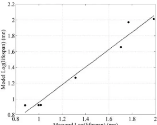
Experimental tests at the center of the level domain and for other constraint levels must be implemented in order to verify the exactitude of the mathematical model. This first test is run for V = 1.73 kV, F = 8.7 kHz, T = 26.7°C (cf. Table II). Results show that Log(L)=1.43 at the center of the domain is very close to the value given by the model, i.e. 1.45 (only 1.4% error). Additionally, other points inside the experimental domain are checked, such as the 7 points in Table VII. To conclude, it can be seen that the maximum error is only around 10%. Additionally, the model validity can also be checked on a plot in Fig. 6, where the model results are plotted versus the experimental results. This quasi-linear pattern denotes a satisfactory correlation between model and experiments.
TABLEVII
EXPERIMENTAL POINTS FOR MODEL VERIFICATION I.E. POINTS INSIDE THE EXPERIMENTAL DOMAIN BUT NOT INCLUDED IN TABLE III
V level F level T level Exp. result Model Diffe-rence 2kV, 10 kHz, 117.5 °C 0.26 0.26 0.64 1.02 0.92 -9.1% 1.7 kV, 15 kHz, 26.7°C -0.03 1.00 0.01 1.31 1.27 -3.5% 1.7 kV, 8.6 kHz, 180°C -0.03 -0.01 1.00 1.00 0.92 -7.5% 3 kV, 8.6 kHz, 26.7°C 1.00 -0.01 0.01 0.88 0.92 4.4% V=1kV, F=8.6 kHz, T=26.7°C -1.00 -0.01 0.01 1.77 1.97 11.5% V=1.73 kV, F=5 kHz, T=26.7°C -0.03 -1.00 0.01 1.70 1.66 -2.9% V=1.73, F=8.6kHz, T=-55°C -0.03 -0.01 -1.00 1.99 2.01 -1.3%
Fig. 6. The diagram effects for the model (from left to right), M is the average lifespan while the other terms are the stress effects.
D. Experiment number reduction
One advantage in the DoE is the possible reduction of the number of experiments and, thereby of the experimental cost. This could be particularly interesting if additional parameters such as pressure and moisture were taken into consideration
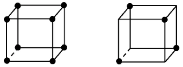
simultaneously with voltage, frequency and temperature. As previously explained, the full experimental plan requires 23=8 experiments in order to test all the combinations and derive the factor and interaction effects. This is illustrated on the left hand diagram of Fig. 7 for 3 factors (3 dimensions) and 2 levels each. It shows that all the combinations of the 3 factors are tested. However a fractional plan could be built, with only 4 experiments instead of 8, testing only 4 combinations of the stress factors, i.e. 2 points per cube face instead of 4.
Fig. 7. Combination representation in case of 3 factors with 2 levels each: full plan on the left = 23=8 possible cases and fractional plan on the right =
half the full plan = 4 experiments out of 8.
With only 4 experiments and 3 factors with 2 levels each, the model will only give the factor effects and not the interaction effects. This strategy may be risky because it involves replacing the study of the interaction between factors 1 and 2 for example, by a third factor in column 5 of Table IV. Consequently, the result of this calculation will be the effect of this 3rd factor aliased by the interaction effect between factors 1 and 2. It is problematic in our case since factor F and interaction VT between V and T are very similar: -0.19 and +0.12 respectively. For example, the effect calculation from the first part of the experimental plan, i.e. the 4 first experiments from Table VIII, leads to the results in the second column of Table IX. Another complementary set of effects which derive from the second part of Table VIII is listed in the third column in Table IX. Interaction V.T is +0.12 in expression (14), consequently, the effect of F appears as -0.07 in Table VIII for the first half plan, i.e. 0.19+0.12 and as -0.31=-0.19-0.12 for the second half plan of Table VIII. Thus, the effect of factor F is aliased by the V.T interaction.
TABLE VIII
FULL FACTORIAL PLAN FOR 3 FACTORS WITH 2 LEVELS EACH =8 TESTS
Test no. M Log(L) Log(F) exp(-bT) Log(L) Weibull 1 1 -1 -1 -1 2.822 2 1 -1 -1 1 1.452 3 1 -1 1 -1 2.457 4 1 -1 1 1 1.165 5 1 1 -1 -1 1.485 6 1 1 -1 1 0.805 7 1 1 1 -1 1.187 8 1 1 1 1 0.2 TABLE IX
FACTORIAL PLAN FOR 3 FACTORS WITH 2 LEVELS EACH
1° half plan 2° half plan
M 1.4 1.5
Log(V) -0.555 -0.497
Log(F) -0.07 -0.31
exp(-bT) -0.575 -0.507
V. CONCLUSION
Thanks to the application of the DoE methodology in this study, a new lifespan model has been defined and verified. This model presents an original relationship between the insulation lifespan and the stress parameters. It involves a logarithm form of the electrically applied stress and an exponential form of the temperature and interactions between these factors. Results show that, in a partial discharge regime, the applied voltage and the temperature have a higher decreasing effect on the insulation lifespan than the frequency. Moreover, these highly influent factors have the most significant interaction. It has been shown that due to the interaction level, the use of fractional plans is not the ideal choice and could lead to approximated lifespan modeling.
Other constraints such as pressure and humidity will be added in future work to take more factors into account Moreover, surface response methodology will help to give other non-linear forms to the lifespan models in order to improve accuracy or to extend the validity domain mainly towards low constraint levels. Our final and long term objective is to test stator prototypes during the design phase of the V-model. Consequently, particular attention will be paid to the reduced number of samples with the help of Bayesian estimation. Twisted pairs will be studied according to the same methodology. Subsequently, stator coils portions will be taken into consideration.
REFERENCES
[1] P.J. Tavner, “Review of condition monitoring of rotating electrical machines”, IET Electr. Power Appl., vol. 2, no. 4, pp. 215–247, 2008. [2] A. Bellini, F. Filippetti, C. Tassoni, and G.A. Capolino, “Advances in
diagnostic techniques for induction machines”, IEEE Trans. Ind.
Electron., vol. 55, no. 12, pp. 4109–4126, Dec. 2008.
[3] S. Grubic, J. M. Aller, B. Lu, and T.G. Habetler, “A Survey on Testing and Monitoring Methods for Stator Insulation Systems of Low-Voltage Induction Machines Focusing on Turn Insulation Problems”,
IEEE Trans. Ind. Electron., vol 55, no. 12, pp. 4127–4136, Dec. 2008.
[4] Gandhi, T. Corrigan, and L. Parsa, "Recent Advances in Modeling and Online Detection of Stator Interturn Faults in Electrical Motors ", IEEE
Trans. Ind. Electron., vol. 58, no. 5, pp. 1564-1575, May 2011.
[5] Smet, F. Forest, J. Huselstein, and F. Richardeau, “Diagnostics for Electric Machines, Power Electronics & Drives”, in Proc. IEEE
SDEMPED, 2011, pp. 278–282.
[6] F. Guastavino, A. Ratto, E. Torello, G. Biondi, G. Loggi, and A. Ceci, “Electrical aging tests on different nanostructured enamels subjected to severe voltage waveforms”, Proc. IEEE SDEMPED, 2011, pp. 278–282. [7] J. Yang, S.B. Lee, J. Yoo, S. Lee,Y. Oh, and C. Choi, "A Stator
Winding Insulation Condition Monitoring Technique for Inverter-Fed Machines", IEEE Trans. Power Elec., vol. 22, no. 5, pp 2026-2033, 2007.
[8] V.I.J. Kokko, “Electro-thermal ageing in lifetime estimation of hydroelectric generator stator windings”, in Proc. IEEE SDEMPED,
2011, pp. 294-299.
[9] G. Mazzanti, “The combination of electro-thermal stress, load cycling and thermal transients and its effects on the life of high voltage ac cables”,
IEEE Trans. Dielec. and Elec. Insul. vol. 16, no.4, pp. 1168–1179,
2009.
[10] J.P Crine, “On the interpretation of some electrical aging and relaxation phenomena in solid dielectrics”, IEEE Trans. Dielec. Elec. Insul., vol. 12, no. 6, pp. 1089-1107, Dec. 2005.
[11] A.C. Gjaerde, “Multi-factor ageing models-origin and similarities”, in Proc. IEEE Electrical Insulation and Dielectric Phenomena Conference, 1995, pp. 199–204.
[12] R. Bartnikas, R. Morin, “Multi-stress aging of stator bars with electrical, thermal, and mechanical stresses as simultaneous acceleration factors,
IEEE Trans. Ener. Conv., vol. 19, no. 4, pp. 702–714, 2004.
[13] N. Lahoud; J. Faucher; D. Malec, and P. Maussion, “Electrical ageing modeling of the insulation of low voltage rotating machines fed by inverters with the design of experiments (DoE) method”, in Proc. IEEE
SDEMPED, 2011, pp. 272–277.
[14] P. Lall, C. Bhat, M. Hande, V. More, R. Vaidya, and K. Goebel, "Prognostication of Residual Life and Latent Damage Assessment in Lead-Free Electronics Under Thermomechanical Loads,"
IEEE Trans. Ind. Electron., vol. 58, no. 7, pp. 2605–2616, 2011.
[15] S.S.H. Zaidi, S. Aviyente, M. Salman, K.K. Shin, and E.G. Strangas, "Prognosis of Gear Failures in DC Starter Motors Using Hidden Markov Models", IEEE Trans. Ind. Electron., vol. 58, no. 5, pp. 1695-1706, May 2011.
[16] C. Chen, B. Zhang, G. Vachtsevanos, and M. Orchard, "Machine Condition Prediction Based on Adaptive Neuro–Fuzzy and High-Order Particle Filtering", IEEE Trans. Ind. Electron., vol. 58, no. 9, pp. 4353-4364 , Sept. 2011.
[17] R.A. Fisher, The Design of Experiments, Edinburgh, Oliver and Boyd, 1935.
[18] L. Gang, Y.G. Guo, J.G. Zhu, X.M. Chen, W. Xu, and K.R. Shao, “Sequential Subspace Optimization Method for Electromagnetic Devices Design With Orthogonal Design Technique”, IEEE Trans.
Magn., vol 48 , no. 2 , pp. 479–482, 2012.
[19] I.P. Brown, and R.D. Lorenz, “Induction Machine Design Methodology for Self-Sensing: Balancing Saliencies and Power Conversion Properties”, IEEE Trans. Ind. Appl., vol. 47 , no. 1, pp. 79–87, 2011. [20] M.S. Islam, R. Islam, T. Sebastian, A. Chandy, and S.A. Ozsoylu,
“Cogging Torque Minimization in PM Motors Using Robust Design Approach”, IEEE Trans. Ind. App., vol. 47, no. 4, pp. 1661–1669, 2011. [21] K. Yamazaki, and H. Ishigami, “Rotor-Shape Optimization of Interior-Permanent-Magnet Motors to Reduce Harmonic Iron Losses”, IEEE
Trans Ind. Electron., vol 57, no. 1, pp. 61–69, 2010.
[22] S. R. Cove, M. Ordonez, F. Luchino and John E. Quaicoe, “Applying Response Surface Methodology to Small Planar Transformer Winding Design", IEEE Trans. Ind. Electron., vol. 60, no.2, pp 483-493, 2013. [23] H-R. Choi, and G-H. Choe, A multiobjective parametric optimization for
passenger-car steering actuator", IEEE Trans. on Ind. Electron., vol. 57, no. 3, pp. 900-908, 2010.
[24] H.M. Hasanien, and S.M Muyeen, “Design Optimization of Controller Parameters Used in Variable Speed Wind Energy Conversion System by Genetic Algorithms”, IEEE Trans. on Sust. Energy, vol. 3, no. 2, pp. 200 – 208, 2012.
[25] S. Rahmani, N. Mendalek, and K. Al-Haddad; “Experimental Design of a Nonlinear Control Technique for Three-Phase Shunt Active Power Filter”, IEEE Trans. Ind. Elec., vol. 57, no. 10, pp 3364–3375, 2010. [26] J. Faucher, P. Maussion, “On-line electrical quality improvement of a
single-phase boost rectifier with fuzzy controller and experimental designs”, in Proc. Electromotion, vol. 13, no. 3, July/Sept., 2006. [27] F. Chan, and H. Calleja, “Design Strategy to Optimize the Reliability of
Grid-Connected PV Systems”, IEEE Trans. Ind. Electron., vol. 56, no. 11, 2009.
[28] Yi-Hwa Liu, and Yi-Feng Luo, “Search for an Optimal Rapid-Charging Pattern for Li-Ion Batteries Using the Taguchi Approach”, IEEE Trans.
Ind. Electron., vol. 57, no. 12, pp. 3963–3971, 2010.
[29] Y. Khelil, P. Maussion, and T. Lebey, “Experimental designs for tracking the influent operating parameters on insulation reliability”, in
Proc. IEEE SDEMPED, 2009, pp 1-6.
[30] J.P. Crine, “When Taguchi meets water treeing”, IEEE Electr. Insul.
Mag., vol. 16, no. 3, pp. 13-18, 2000.
[31] D.F. Ortega, and F. Castelli-Dezza, “On line partial discharges test on rotating machines supplied by IFDs”, Proc. IEEE ICEM, 2010, pp. 1 -4. [32] G. Cavallini, D. Montanari, D. Fabiani, and M. Tozzi, “The influence of PWM voltage waveforms on induction motor insulation systems: perspective for the end user”, in Proc. IEEE SDEMPED, 2011, pp. 288– 293,
[33] F. Guastavino, A. Dardano, E. Torello, and G.F. Massa, “PD activity
inside random wire wound motor stator insulation and early failures: A case study analysis ”, in Proc. IEEE SDEMPED, 2011, pp. 283–287. [34] B. Bertsche, Reliability in Automotive and Mechanical Engineering
Determination of Component and System Reliability, Springer, 2008.
[35] N. Lahoud, M.Q. Nguyen, P. Maussion, D. Malec and D. Mary, “Using the Design of Experiments (DoE) to Elaborate an Electrical Ageing Model for the Insulation of Low Voltage Rotating Machines Fed by Inverters”, in Proc. IEEE Int. Conf. Sol. Dielectr, pp. 24-27, 2010. [36] G. Stone, E.A. Boulter, I. Culbert, and H. Dhirani, Electrical insulation
for rotating machines, IEEE Press, J. Wiley & Sons, 2004.
[37] S.S. Shapiro, and M.B. Wilk, “An analysis of variance test for normality”, Biometrika, vol. 52, no. 3-4, pp 591-611, 1965.
[38] Normal Probability Plot, National Institute of Standards and
Technology, Engineering Statistics Handbook, Available: http://www.itl.nist.gov/div898/handbook/eda/section3/normprpl.htm [39] C. Ritz, and J. C. Streibig, Nonlinear Regression with R, Springer, 2008.
Nadine Lahoud received the M.Sc. degree in
Polymer Materials Science from the Université
Claude Bernard Lyon1, France in 2005 and the
Ph.D. degree from the Université de Toulouse, France in 2009. Her thesis topic concerned the organic electrical insulation ageing. A phenomenological approach has been developed to describe the multi-parameters aspect of this process. In 2009/10, she held a postdoctoral position at LAPLACE, where she worked with the design of experiments for the electrical insulation lifespan modeling. In 2012, she has started to work on flight integration systems at Airbus France.
Jerome Faucher received his M. Sc and PhD in
Automatic and Electrical Engineering from University of Toulouse, Institut National Polytechnique (France) in 2003 and 2006 respectively. He currently works for AIRBUS in the Electrics System department.
David Malec was born in France in 1964. He got
the Eng. degree in 1992 from the Conservatoire
National des Arts et Métiers and the Ph.D. degree
in 1996 from Paul Sabatier University of Toulouse, where he is Professor in the Electrical Engineering department. His scientific activities deal with the study of solid insulating materials (polymers and ceramics) used in both low and high voltage electrical engineering domains. He is a Senior-member of the SEE (French Society of Electricians and Electronics Specialists) and an active member of the SFE (French Society of Electrostatics).
Pascal Maussion (member IEEE) got his MSc
and PhD in Electrical Engineering in 1985 and 1990 from Toulouse Institut National Polytechnique (France). He is currently full Professor at the University of Toulouse and with LAPLACE, Laboratory for PLAsma and Conversion of Energy. His research activities deal with control and diagnosis of electrical systems (power converters, drives, lighting) and with the design of experiments for optimisation in control and diagnosis. He is currently Head of Control and Diagnosis group in LAPLACE. He teaches control and diagnosis in a school of engineers.