HAL Id: in2p3-00919757
http://hal.in2p3.fr/in2p3-00919757
Submitted on 17 Dec 2013HAL is a multi-disciplinary open access archive for the deposit and dissemination of sci-entific research documents, whether they are pub-lished or not. The documents may come from teaching and research institutions in France or abroad, or from public or private research centers.
L’archive ouverte pluridisciplinaire HAL, est destinée au dépôt et à la diffusion de documents scientifiques de niveau recherche, publiés ou non, émanant des établissements d’enseignement et de recherche français ou étrangers, des laboratoires publics ou privés.
Design of the RF system for a 250 A.MeV
superconducting cyclotron
M. Maggiore, L. Calabretta, M. Di Giacomo
To cite this version:
M. Maggiore, L. Calabretta, M. Di Giacomo. Design of the RF system for a 250 A.MeV superconduct-ing cyclotron. 17th International Conference on Cyclotrons and their Applications, Oct 2004, Tokyo, Japan. pp.1-3. �in2p3-00919757�
DESIGN OF THE RF SYSTEM FOR A 250 A.MEV SUPERCONDUCTING
CYCLOTRON
M.Maggiore (a,c), L.Calabretta (a), M. Di Giacomo (b)
(a) Laboratori Nazionali del Sud, INFN - 64, Via S.Sofia I-95123 Catania (b) Grand Accélérateur National d’Ions Lourds, Bvd. H. Becquerel F-14076 Caen
(c) University of Catania, Dept. of Physics, Via S.Sofia I-95123 Catania
Abstract
A superconducting cyclotron accelerating q/A=0.5 ions up to 250 A.MeV, for medical applications and radioisotopes production (SCENT project) is being studied at Laboratori Nazionali del Sud in Catania. The RF system, working in the fourth harmonic, is based on four cavities operating at 93 MHz, which are connected in the central region. The paper describes an unusual multi-stem RF design, performed with 3D electromagnetic codes. The aim is to obtain a cavity, completely housed in the valley, with a voltage distribution going from 65 kV in the injection region to a peak value of 120 kV in the extraction region, and a low power consumption.
INTRODUCTION
Superconducting cyclotron RF systems typically work in the range 10-50 MHz and need big apertures in the pole to house the vertical stems. The cavities are half-wave resonators, practically symmetric with respect to the median plane, characterised by strongly spiralled electrodes (dees). In the case of the SCENT machine, whose extraction diameter is 130 cm, the size of the dees is large and we searched for a solution which allows us to house the resonators inside the valleys. The available depth in the valley is of ±45 cm respect to the median plane. For this reason and to maximize the energy gain it
was decided to work in the 4th harmonic at 93 MHz.
To minimize the risk of discharges, voltages lower than 70 kV are required in the area of the central region, while voltages around 120 kV or higher are required at the outer radius to achieve an adequate turn separation of the beam extracted by the electrostatic deflectors. Due to the strong spiral angle, the electrode equivalent length is around 2.5 metres which results in a capacity of more than 200 pF. In order to control the radial voltage distribution and to obtain the required resonant frequency, a multi-stem configuration is then the only feasible solution [1,2].
THE MODELING METHOD
For simplicity’s sake, we will consider the median symmetry plane and talk about quarter-wave resonators (QWR). A multi-stem QW resonator can in principle be modelled as several paralleled QWR, having all the same eigen-frequency and whose field distribution stays almost unchanged if they are coupled in such a way that they don’t interact each other. This is feasible when the stems are far enough apart, and each QWR is simulated with the proper boundary conditions, as we shall see later.
Each QWR consists of one stem, charged on one section of the electrode. Such a structure usually presents a voltage distribution having a minimum near to the stem base and increasing towards the dee extremities.
The combination of two or more structures like this, gives a voltage distribution where the adjacent maxima join in a plateau as no current has to flow in either direction.
By cutting the dee into sections of different length, it is possible to obtain several different profiles, where the lower voltage will correspond to the minimum of the section with higher capacity.
To simulate each section with the proper boundary conditions, we tested two different solutions, both giving comparable results.
Figure 1: example of cavity subdivision. Normal magnetic boundaries are selected on the vertical surfaces.
In the first case, a magnetic symmetry condition is set among two adjacent stems as shown in figure 1. This method greatly reduces the number of mesh cells. In the second case, tested on a simplified structure, each stem with its section of dee, is simulated in the whole cavity volume.
In both cases the stem position and diameter are adjusted in order to obtain the required voltage distribution and frequency. For this last adjustment, we know that, lowering the cut frequency of each portion, arises the local voltage level. Then the whole structure is simulated using the geometry found in this way, and few local adjustments are done to compensate the effects of the method’s approximations.
At least one simulation of the whole volume is required to check the position of other resonant modes that could be not too close. In the case of a 3-stem structure, for instance, the two nearest modes typically have voltages of
opposite sign on the dee extremities, or lower voltages on the extremities than on the central part.
In order to optimize the shunt impedance, we have chosen to have higher electrode voltages on the inner and outer extremities and to keep a lower voltage in the most part of the dee. The obtained resonator is shown in fig 2.
The big central stem (low inductance) concentrates the currents coming from most of the electrode, while the two lateral ones (high inductance) resonate with the much smaller capacites of the dee extremities.
.
Figure 2: layout of the cavity
THE CAVITY GEOMETRY
The total height of the half-wave cavity is 80 cm, while a vertical aperture of 30 mm along the median plane is left for the beam.
In order to reduce the dee capacity and the electric field, the acceleration gap size ranges from 1.5 cm at inner radii to 6 cm at the outer end.
Figure 3: layout of a dee between the poles The electrode’s angular width gradually increases up to 39 degrees near to the first stem, then it is rather constant in the proximity of the main stem and decrease down to 23 degrees at full radius (see fig. 3).
The three stems are centred at radii 30, 90 and 120 cm. Their diameters are 8.6 cm for the external stem and 10 cm for the internal stem. The main stem extends 32 cm radially and up to 30 deg azimuthally.
RF SIMULATION RESULTS
The simulations have mainly been performed with the eigenmode module of Microwave Studio (MWS) [3] and table 1 reports the calculated parameters.
Table 1: RF cavity parameters
Parameters value
Resonance frequency ∼ 93 MHz
Voltage range 30-160 KV
Quality factor ∼ 8500
Max power density 16 W/cm2
RF Power ∼ 45 KW
E Max 10 MV/m
Mode 2 98 MHz
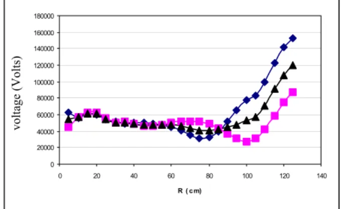
The effective voltage distribution, going from 60 kV in the injection region to a peak value of 120 kV in the extraction region, is shown in figure 4. The values are obtained by integrating the electric field profiles across the gaps in the median plane of the cavity: it has to be noted that, due to the reduced width of the electrode in the injection region, the transit time factor is there very low.
0 20000 40000 60000 80000 100000 120000 140000 160000 180000 0 20 40 60 80 100 120 140 R ( c m) voltage (Volts)
Figure 4: effective voltage vs radius: the internal gap distribution (squares), the external one (diamonds) and the average (triangles).
Loss calculations were also carried out with the SOPRANO code.
SOPRANO [kW] MWS [kW]
LINER 7.50 7.60
DEE 4.40 7.33 (dee + main stem)
INTERNAL STEM 2.14 1.87
EXTERNAL STEM 4.87 5.25
MAIN STEM 1.76
TOT for 120 kV@130 cm 20.67 22.05
Total losses per cavity 41.34 44.10
Table 2: comparison between losses calculated with SOPRANO and MWS for different cavity elements
To take into account the surface roughness and the average working temperature, the copper conductivity has
been set as 5.0x10⁷ S/m instead of 5.8x10⁷. Results are
summarized in table 2. The current distribution on the dee surface is shown in figure 5, which shows very clearly how the different sections interact with the stems.
The maximum current density is about 69 amp/cm and is located on the edges of the two gaps near to the external stem. High currents are also visible at the base of the external stem, requiring special care for the connection to the electrode.
Figure 5: current distribution on the dee ; current values at the short-circuit plate are given in boxes
Figure 6 is a closer view of the critical areas of figure 5 and shows the corresponding loss values. The currents, coming from the large radii, gather along the gaps towards the stem and heat the electrode along the gap.
The maximum power density is estimated at 16 watt/cm2,
for a peak voltage of 120 kV.
Figure 6: power density distribution (watt/m2) for 150 kV
of peak voltage. The peak value is 25 watt/cm2.
COUPLER DESIGN
The inductive coupling has been chosen to feed the RF power into the cavity. Simulations, performed with MWS, has shown that it is possible to get critical coupling with reasonable loop dimensions near all the different stems: i.e, positioning the loop near to the main one, requires a
loop surface around 20 cm2.
Figure 7: inductive loop layout.
CONCLUSION
Multi-stem cavities are a good solution to the design of cyclotron resonators with challenging dee shapes and dimensions. Although the degrees of freedom of the structure grow with the number of stems, the RF design can be approached with some simple but realistic approximations that, with the help of modern 3D EM codes, lead to a quick definition of the stem diameters and positions. Then, multi-stem cavities can easily be designed to provide the voltage distribution needed to optimize the power consumption, to reach high resonant frequencies in spite of the dee dimensions, and to reduce the current densities and the total losses. Last but not least, using more stems will also help to increase the mechanical stability of the structure and allows us to provide an easier path for the dee cooling pipes.
ACKOWLEDGEMENT
The authors want to thank Mr. D. Battaglia and Mr. L. Piazza of the Engineering Dept. of Catania’s University for his contribute to the cavity and inductive coupler design and Mr. A. Caruso of the Laboratori Nazionali del Sud for his technical suggestions for cavity improvements.
REFERENCES
[1] E.Acerbi et al., “Design of the RF cavity for a 200
MeV PSC”, 14th ICCA 1995, Sout Africa.
[2] C.Bieth et al.,”A very compact protontherapy facility
based on use of HTS”, 15th ICCA 1998, Caen, June.
[3] MWS by CST www.cst.de.