Publisher’s version / Version de l'éditeur:
Vous avez des questions? Nous pouvons vous aider. Pour communiquer directement avec un auteur, consultez la
première page de la revue dans laquelle son article a été publié afin de trouver ses coordonnées. Si vous n’arrivez
pas à les repérer, communiquez avec nous à [email protected].
Questions? Contact the NRC Publications Archive team at
[email protected]. If you wish to email the authors directly, please see the
first page of the publication for their contact information.
https://publications-cnrc.canada.ca/fra/droits
L’accès à ce site Web et l’utilisation de son contenu sont assujettis aux conditions présentées dans le site
LISEZ CES CONDITIONS ATTENTIVEMENT AVANT D’UTILISER CE SITE WEB.
Proceedings, ASCE Specialty Conference on The Northern Community: A Search
for a Quality Environment, pp. 705-718, 1981
READ THESE TERMS AND CONDITIONS CAREFULLY BEFORE USING THIS WEBSITE.
https://nrc-publications.canada.ca/eng/copyright
NRC Publications Archive Record / Notice des Archives des publications du CNRC :
https://nrc-publications.canada.ca/eng/view/object/?id=5770774c-ce7c-4449-93dc-3ab0523612c4
https://publications-cnrc.canada.ca/fra/voir/objet/?id=5770774c-ce7c-4449-93dc-3ab0523612c4
NRC Publications Archive
Archives des publications du CNRC
This publication could be one of several versions: author’s original, accepted manuscript or the publisher’s version. /
La version de cette publication peut être l’une des suivantes : la version prépublication de l’auteur, la version
acceptée du manuscrit ou la version de l’éditeur.
Access and use of this website and the material on it are subject to the Terms and Conditions set forth at
Chilled gas pipeline: frost heave design
S e r
8 8 5 0
TH1
N21d
1
Council Canada
National Research
Conseil national
de recherches Canada
no.
987
c.
2
ICHILLED GAS PIPELINE
-
FROST HEAVE DESIGN
by
OttoJ.
SvecANALYZED
Reprinted from
Proceedings, ASCE Specialty Conference on The Northern Community: A Search for a
Quality Environment
held 8
-
10 April 1981 in Seattle, Washingtonp. 705. 718
E
N IBLDG. P,E~.~I
1
L I B R A R Y
b
I
DBR Paper No. 98782-
02-
0
2
Division of Building Research
B I B L I ~ T H E Q U E
Rec5. 3; im.
i
YI-UlrC--- - - SOMMAIRE Le p r e s e n t a r t i c l e donne une v u e d ' e n s e m b l e d e c e r t a i n s d e s p r o b l S m e s p r e v i s i b l e s q u i d e c o u l e n t du s o u l ~ v e m e n t p a r l e g e l d ' u n p i p e l i n e a c h e m i n a n t d e 1 ' A r c t i q u e du gaz r e f r i g e r e . Les d i s c u s s i o n s r e l a t i v e s 2 l a c o n c e p t i o n du p i p e l i n e d a n s d i v e r s e s l o c a l i t g s t r a i t e n t d e s s o l s non g e l & , d e s berrnes, du p e r g e l i s 0 1 peu p r o f o n d , d e s i n t e r f a c e s e n t r e z o n e s g e l g e s e t non g e l g e s , e t d e s p a s = ~ n o - -..--1---..- -1-0 - ; . . i Z - n n T L ' S J J P P I I T t e n t e d e d C f i n i r l e s n c e , l e u r i m p l e s s o n t aPP modele b i d I d i f f 6 - r e r s e . La pos LSvement Pal e s u l t a t s e x &
-.
_.Reprinted from the Proceedings
of the Specialty Conference on
THE NORTHERN COMMUNITY: A SEARCH FOR
A QUALITY ENVIRONMENT
ASCEI~eattle,
~ashington/April8-10,
1981
Otto J. Svec I
ANALYZED
I
ABSTRACTThis paper presents a review of some of the anticipated problems associated with the frost heave of an Arctic chilled gas pipeline. The discussions of pipeline design in various locations include unfrozen ground, berm, shallow permafrost, frozen-unfrozen interfaces and river crossings. The author attempts to define the problems as well as prove their existence, their importance, and the necessity to deal with them. The discussions are supported by numerical results from a two-dimensional finite difference heat conduction-convection model, including gradual phase change. A possible engineering solution to the frost heave problem of a chilled gas pipeline is supported by the experimental results.
I
INTRODUCTIONDuring the freezing of frost susceptible soils not only does in situ water change into ice with a 9 per cent increase of volume but also large amounts of water migrate toward the freezing front. This additional water accumulate s i n the freezing fringe behind the 0°C isotherm
in
the form of ice lenses and causes the upper layers of soil to heave. The water migration and, consequently, the frost heave rate are dependent on theI
over-all heat extraction, applied pressure, hydraulic conductivity, type of soil and other factors. Many researchers since the early thirties have tried to determine the basic physical processes occurring ini
freezing soils, but only during the last decade, and particularly inrecent years, has substantial progress been made. This progress is represented by two important findings: existence of freezing fringe (1,
! 2, 3), and validity of the Clausius-Clapeyron equation
(4).
This success, is a direct result of the accelerated research efforts associated with I increased exploratiofi and engineering activity in the Arctic. In spite
I of indications that the physics behind freezing of soils is now under-
stood, a mathematical description or an engineering theory of frost heave
I
remains an illusion. As the state-of-the-art of the frost heave problem is well beyond the scope of this paper and can be found in Ref. 5, only ai
few comments follow.I Research Officer, Geotechnical Section, Division of Building Research, National Research Council of Canada, Ottawa, Ontario, KIA OR6
706 NORTHERN COMMUNITY ENVIRONMENT
C u r r e n t r e s e a r c h is concerned w i t h a ) b a s i c thermodynamic
p r o c e s s e s i n s o i l m i c r o s t r u c t u r e , b) s o i l c l a s s i f i c a t i o n i n r e s p e c t t o i t s f r o s t s u s c e p t i b i l i t y , c ) e m p i r i r a l r e l a t i o n s a r i s i n g from I
l a b o r a t o r y s t u d i e s t o g e t h e r w i t h e f f o r t s t o a p p l y them t o the f i e l d , and
d ) f u l l - s c a l e t e s t s on s t r u c t u r e s endangered by t h e f r o s t heave ( c h i l l e d n a t u r a l gas p i p e l i n e s , b u i l d i n g f o u n d a t i o n s . b r i d g e s , r o a d s , e t c . ) .
There have n l s o been many a t t e m p t s t o p r e d i c t f r o s t h e a v e by n u m e r i c a l ' models hased on thermodynamics of m i c r o s t r u c t u r e , e m p i r i c a l I a b o r a c o r y
results, a n a l o g i e s between f r e e z i n g and d r y i n g , e t c . Some o f these models, u s i n g e i t h e r f i n i t e d i f f e r e n c e o r f i n i t e element t e c h n o l o g y ( 6 .
7. 8, 9. 10). t r y t o i n c l u d e t h e most i m p o r t a n t f a c t o r i n f r o s t heave p r o c e s s e s , i.e.. t h e h y d r a u l i c p o t e n t i a l d r i v i n g t h e water toward t h e f r e e z i n g f r i n g e . E n l e e s t h i s mechanism i s c o n s i d e r e d i n a p r o p e r l y coupled h e a t and mass f l o w model, f r o s t heave p r e d i c t i o n s w i l l p r o b a b l y remain u n s u c c e s s f u l . The p r e s s i n g need f o r new e n e r g y sources w i l l force
a s o l u t i o n t o t h e s e prohlems even i f i t means o v e r d e s i g n of the f r o s t heave p r o t e c t i v e measures. For example, i n a c h f l l e d gas p i p e l i n e i n t h e A r c t i c t h e d e s i g n h a s t o be s a f e , w i t h minimal risk o f r u p t u r e s s i n c e
t h e s e can be v e r y c o s t l y .
T h i s p a p e r d e a l s v i t h an a n a l y s i s o f p o t e n t i a l f r o s t h e a v e problems of a c h i l l e d g a s p i p e l i n e . A n u m e r i c a l F i n i t e d i f f e r e n c e s t u d y t o g e t h e r
w i t h e x p e r i m e n t a l model i n v e s t i g a t i o n s show the p o t e n t i a l problems of v a r i o u s design schemes. The computer model i s based on heat and mass
t r a n s f e r i n f r e e z i n g s a t u r a t e d s o i l s w t t h o u t , however, i n c l u d i n g w a t e r m i g r a t i o n due t o f r e e z i n g . A s i m u l t a n e o u s one-dimensional e x p e r i m e n t a l
and n u m e r i c a l s t u d y i s now under way i n which a t t e m p t s a r e b e i n g made t o d e f i n e and e v a l u a t e s u c t i o n p o t e n t i a l s i n i t i a t e d and s u s t a i n e d d u r i n g t h e f r e e z i n g p r o c e s s . The upper bound s o l u t i o n i s g i v e n by assuming the
maximum amount of i c e l e n s a c c u m u l a t i o n .
PROBLEM DEFINITION
F r o s t heave w i l l o c c u r i f t h e s o i l under c o n s i d e r a t i o n i s f r o s t s u s c e p t i b l e , i f t h e r e i s a v a i l a b l e w a t e r t o m i g r a t e toward t h e f r e e z i n g f r o n t , and i f t h e r a t e of h e a t removal i s w i t h i n c e r t a i n l i m i t s . The f i r s t two c o n d i t i o n s a r e s e l f - e v i d e n t , h u t t h e t h i r d r e q u i r e s some d e f i n i t i o n . There a r e t h r e e p o s s i b i l i t i e s :
( a ) h e a t i s removed s o f a s t t h a t a r a p i d f r o s t p e n e t r a t i o n t o g e t h e r w i t h w a t e r e x p u l s i o n w i l l o c c u r ( l l ) ,
( b ) r a t e of h e a t removal i s moderate, c a u s i n g r e l a t i v e l y slow o r even z e r o f r o s t p e n e t r a t i o n ,
(c) r a t e of h e a t removal i s lower t h a n h e a t i n f l u x , r e s u l t i n g i n thawing
-
of t h e f r o z e n s o i l . T h e r e i s a l s o a n o t h e r f a c t o r c o n t r o l l i n g t h e f r o s t heave-
i n t e n s i t y of overburden p r e s s u r e . I t i s t h e o r e t i c a l l y p o s s i b l e t o d e c r e a s e o r e l i m i n a t e f r o s t heave i n f r e e z i n g s o i l s by i n c r e a s i n g overburden p r e s s u r e . The n e c e s s a r y l o a d t o a r r e s t h e a v i n g c o m p l e t e l y , however, i s Out o f p r a c t i c a l e n g i n e e r i n g l i m i t s .I
CHILLED
GAS
PIPELINEWhen the first condition, frost susceptibility, is considered, the only practical but limited solution that can be offered
is
partial soil Ireplacement by sand or gravel. Granular materials such as these, unless they contain silty or clay particles, cannot produce sufficient suction forces to induce appreciable water flow required for segregational frost heave. In fact, the design of a chilled gas pipeline usually calls for .a
'
ahallow laver of gravel underneath the pipeline. This is not a solution, bur only a weak measure to postpone slightly the Initiation of frostheave.The second condition, the availability of water, is very difficult to control and will not be discussed in this paper.
It follows that the only variable that can be manipulated is heat removal or alteration of direction of heat flow. Under this category the following avenues of action can be considered in order to minimize frost heave :
I
(a) lower the rate of heat removal (insulation around the pipe);I
(b) change the direction of heat flow (flat insulation under the pipe); (c) introduce a heat source to balance the heat sink effect of the pipe(heating cables) ;
I
(d) combinations of the preceding;(e) use natural solar heat for warming thermally replenished soil by the pipeline (pipe in the berm); and
(f) use well-undercooled gas to achieve a large frost bulb around the pipe in very short time.
I
NUMERICAL MODELThe computer program based on the mathematical model developed in this paper includes both heat and moisture flows. However, owing to a lack of knowledge regarding the applicable material hydraulic properties and suction potentials due to freezing, the numerical results are based on heat flow with forced convection only.
A two-dimensional heat transfer equation for soil-water systems
1
undergoing a phase change in absence of a vapour transfer can be writteni
as follows:d$ where c = c -
L-
I
708 NORTHERN COMMUNITY ENVIRONMENT
The unfrozen water content, 0 , at temperature, T, below freezing can be approximated by:
t
Equation 2 is used to calculate
0,
the rate of the waterlice phase change transition. It also represents one of the coupling mechanisms between heat and moisture flows. The thermal conductivity, h , is calculated according to Kersten (12). At a boundary of two soil layers the following geometric approximation is used:During the phase transition, h is calculated on the basis of water and ice fractions.
A computer program based on the finite difference method has been written in the FORTRAN language. The values of the heat capacity, thermal conductivity and unfrozen water content for a given grid point and time are expressed by explicit linearization from their values at the preceding time step. The freezing Fringe tracks down behind the moving
0°C isotherm. An over-all heat balance computed at every t h e step indicates the total heat crossing all the boundaries, including internal
heat sinks and sources. An iterative solution of an implicit approxima- tion of the partial differential equations, together with a built-in acceleration technique, have been used. A satisfactory convergency
has
been achieved by a time-step-cutting schema basedon
the convergency rate during the iterationas
well as on theover-all
heat balance. All the stationary and moving boundary conditions are defined in a time-dependent and space-wise general way with the moving freezing front. The inside heat sources or sinks (for example, heating cables or pipes,respectively) were treated by using internal boundary conditions.DESIGN ALTERNATIVES
As an engineering frost heave theory has not yet been developed (a theory that would include water migration toward freezing front induced by freezing), the results given below are based on the heat balance equation only. The convection component in this equation is associated with forced flow. Because ice segregation cannot be modelled in a true sense, lower and upper bound solutions seem reasonable. The worst possible case (the upper bound solution) can be represented by taking the available latent heat equal to that of water and the frost heave equal to the frost penetration (ice segregation ratio = 1). In reality such a situation is highly unlikely. Pipeline designers must, therefore, temper these results with "engineering judgement" aided by experimental data.
CHILLED GAS PIPELINE 709
I
This paper will show the grave risk associated with guesswork inselecting the segregatidnia~io and using it for design purposes. The
I
'
advantages of the heat tracing approach, safety and control, will also be demonstrated.(a) Buried pipe
I
Many preliminary studies performed by natural gas industries and government organizations (13, 14 and 15) show that the most desirable design configurations are those with the pipe placed underground. The potential problem of frost heave has to be considered, however, and protective measures adopted. From the discussion in the earlier part of
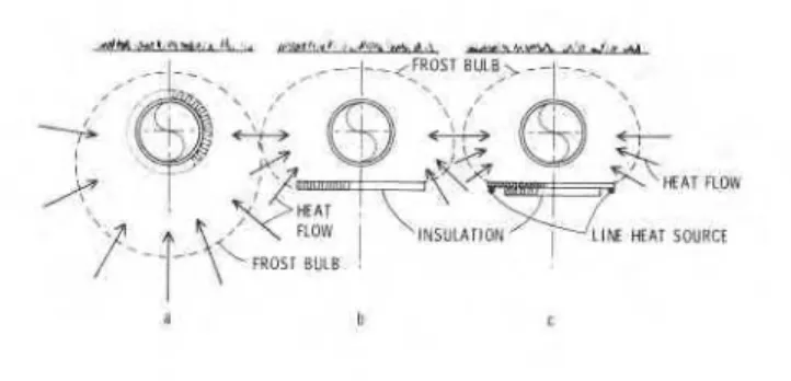
this paper, three possibilities exist (excluding soil replacement): i. to use insulation around the pipe to decrease over-all heat flow,
(Fig. la),
ii. to use flat insulation to change the direction of heat flow, (Fig. lb), and
iii. to use heat sources in combination with insulation to control frost heave (Fig. lc)
.
Case i. The first case has been investigated by a simple numerical parametric study and the results are shown in Fig. 2. It is clear that this particular configuration, if used, wilL be very vulnerable to frost heave. Since the frost bulb is growing, it might be assumed that the circumference of the frost front as well as its distance from the pipe is also increasing. If so, then there should be lower heat flux at the O°C isotherm and a decrease in frost heave. Figure,2 shows, however, that the rate of frost penetration (associated with the heat flux) decreased only after a long period of time. This results from the fact that the frozen ground has higher heat conductivity and the over-all region is constantly cooling. The foregoing assumption is therefore incorrect. As further proof, note that frost penetration (and thus growth of the frost bulb) is controlled by over-all heat balance, including latent heat of migrating water. This means that even if the frost penetration rate is zero, i.e., O°C isotherm is virtually stationary, an ice lens can be forming very quickly. This fact was demonstrated in Ref. 16 where frost penetration versus frost heave was studied. On the other end of the scale, at the high heat flux, even water expulsion can occur (11). The relation between the heat flux and the frost heave is far from linear
(17, 18 and 19). Another practical and as yet unsolved problem is the question of insulation quality (difficulties with geometry and installa- tion) and its protection against moisture during the life of the pipeline.
.
If insulation around the pipe fails after several years and there is nobackup built-in protection, the cost of interruption of operation and necessary repairs will be substantial. Considering all of these facts it must be concluded that use of insulation alone around the pipe, without any other protective measures, is unsatisfactory.
Case ii. It is a well known fact that, in soil, ice lenses grow perpendicular to the direction of the heat extraction. If the heat flow is changed from a vertical to a horizontal direction, the orientation of
NORTHERN COMMUNITY ENVIRONMENT
r'
\
PIOWI
~ I N S U U ~ I O N ' - ~ ' L I w MAT SWRCfl
a b t
Figure 1 A Heat flow in three basic design configurations
TIME. y e a r s
CHILLED GAS PIPELINE 71 1
ice lenses will be altered from horizontal to vertical. Soil deformation due to ice lensing will therefore occur horizontally. For a buried pipe-
? line such deformation is of no practical significance.
This is the basic concept behind the proposal to use horizontal flat
slab insulation under pipelines (Fig. lb). From an installation point of
I
,
view such a configuration is very simple and practical, as compared withinsulation all around the pipe. Also, protection against moisture can be completed by manufacturers before installation.
Case iii. The concept of the following design is the same as that
above, except that it is augmented by two heat sources, (Fig. lc). It
has been shown on an experimental chilled pipeline model (13) that heav- ing of the pipe can be easily controlled by operating two heat sources located under the flat insulation. It was concluded that the heat need not be applied continuously but rather its duration and intensity chosen selectively. Such a system requires monitoring of the pipeline perfor- mance, mainly vertical movements, and perhaps the temperature distribu- tion in the surrounding soil. In fact, since the consequences of heave of Arctic gas pipelines are so serious and difficult, any final design and actual installation will require a certain amount of monitoring.
Because a satisfactory mathematical solution that includes moisture migration induced by freezing has not yet been achieved (mainly due to a lack of complete understanding of the complicated physical processes involved), an experimental procedure devised in Ref. 20 was used in this work. Basically. the system is as follows: a brass pipe (5.08 cm O.D.) mounted on two inner, separate, sliding walls (to allow the pipe to
heave) was placed in a plexiglas box 20.3 x 40.6 x 30.4 cm. The constant
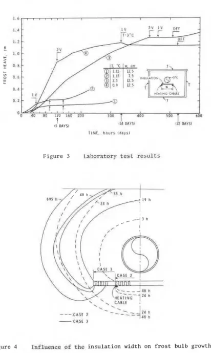
temperature of the pipe was assured by fast circulation of cooling fluid. Slab insulation and two heat tracing cables were placed under the pipe. Good agreement between computer results and experiments was achieved by using non-frost-susceptible saturated sand. For heaving tests highly frost-susceptible Niagara silt was used. Results from these tests did not agree with numerical analysis for the aforementioned reasons. Figure 3 shows the frost heave of the pipe (kept at -3OC) in four tests in which outside temperature T, insulation width W, and
voltage
V
(heat flux) in heating cables were varied. The differencebetween curves 1 and 2 is caused by wider insulation (7.5 cm increased to
12.5 cm). The effect is twofold: frost heaving rates are lower and the
voltage required (heat output) to control heaving of the pipe is also
,
lower. The temperatufe distribution in the soil for cases 2 and 3 isshown in Fig. 4. The effect of wider insulation is clearly visible, particularly on O°C isotherms for 48 hours. Comparison of curves 3 and 4 shows the important effect of outside boundary conditions: the colder
, the ground, the higher the frost heave rates. Note as well that at lower
ground temperatures the temperature gradient is shallower, representing lower heat flux, but the rate of frost heave is greater. This is in
agreement with published results (11). As discussed earlier, the
expectation of smaller frost heave rates as the frost bulb grows is not realized. For warmer ground, the required heat flux from the heating cables (voltage) is smaller. This may be seen from the results of Fig. 3, where at 14 days the temperature of the chamber (outside boundary conditions) increased to 3°C.
N O R T H E R N C O M M U N I T Y E N V I R O N M E N T
1 . 4
-
1 . 2-
(5 DAYS) 114 UnYSi 122 IlAYSt
TIME. h o u r s l d a y s l
Figure 3 Laboratory test results
CHILLED
GASPIPELINE
7 13(b) P i p e l i n e i n a berm
I n o r d e r t o r e d u c e o r perhaps e n t i r e l y e l i m i n a t e t h e f r o s t h e a v e of a c h i l l e d gas p i p e l i n e t h e s e a s o n a l warming e f f e c t i n combination wirh i n s u l a t i o n could be u t i l i z e d . I f t h e p i p e i s p l a c e d i n t h e thermally
a c t i v e s u r f a c e l a y e r . t h e c h i l l i n g p i p e e f f e c t can be i n f l u e n c e d by s e a s o n a l thawback. Moreover, i f t h e p i p e I s placed in a berm ( i . e . , above n a t l l r a l ground l e v e l ) t h e s e a s o n a l t h e r m a l e f f e c t becomes dominant. To e l i m i n a t e i n i t i a t i o n and growth of t h e f r o s t b u l b underneath t h e p i p e t h e i n s u l a t i o n w i l l s t i l l be r e q u i r e d , dependsnt on t h e p i p e temperature.
Although t h i s approach seems t o b e l a g i c a l and p r a c t i c a l t h e r e a r e drawbacks s e r i o u s enough t o p r o h i b i t use o f t h i s p r i n c i p l e even on s h o r t p i p e l i n e s e c t i o n s . F i r s t of a l l , t h e t h e r m a l s e a s o n a l e q u i l i b r i u m (freeze-up and complete thawback) w i l l p r o b a b l y be v e r y s e n s i t i v e , depending on such p a r a m e t e r s a s : changes i n s u r f a c e n - f a c t o r , d e g r e e of compression of t h e p e a t l a y e r underneath t h e p i p e , v e g e t a t i o n a l o n g t h e r o u t e , v a r i a b i l i t y of snow cover and w e a t h e t , changes i n a v a i l a b i l i t y of s o l a r r a d i a t i o n Erom y e a r t o y e a r and, e s p e c i a l l y , t h e i n f l u e n c e o f the t h i c k n e s s of i n s u l a t i o n . I n o t h e r words, t h e f a c t o r o f s a f e t y a g a i n s t t h e start of p e r m a f r o s t growth below the p i p e could be l w and probably u n p r e d i c t a b l e .
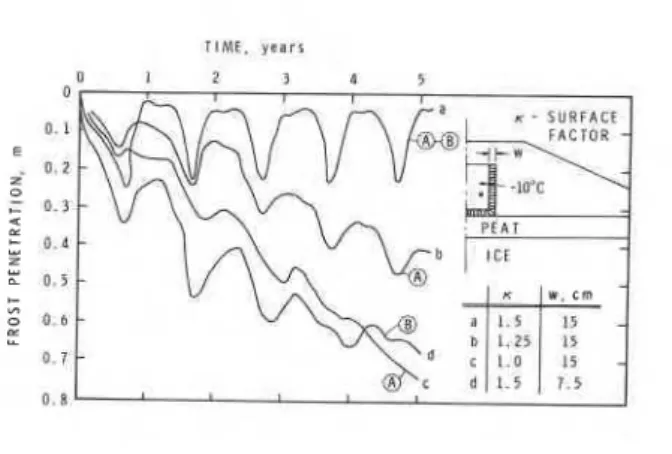
I n o r d e r t o d e m o n s t r a t e t h e v u l n e r a b i l i t y and s e n s i t i v i t y of a weak thermal e q u i l i b r i u m , r e s u l t s o f r e l a t i v e l y s i m p l e c a l c u l a t i o n s a r e shown
i n F i g . 5. The s e t of c u r v e s denoted by t h e l e t t e r A r e p r e s e n t s the i n f l u e n c e of v a r i o u s s u r f a c e c o e f f i c i e n t s ; c u r v e s denoted by the l e t t e r
B
show t h e i n f l u e n c e of t h e t h i c k n e s s o f i n s u l a t i o n . I t i s c l e a r t h a t
o v e r d e s i g n , p a r t i c u l a r l y t h a t due t o u n c e r t a i n t y of i n s u l a t i o n p e r f o r - mance ( v a r i a b l e m o i s t u r e c o n t e n t ) , could be j u s t f f i e d .
An o p p o s i t e s i t u a t i o n may a r i s e i f t h e bemi c o v e r i n g t h e gas l i n e i s
e r e c t e d o v e r a l a y e r of p e r m a f r o s t . Under c e r t a i n c o n d i t i o ~ s d e g r a d a t i o n
of p e r m a f r o s t may o c c u r . Another major drawback of berms i s the requise-
r e n t f o r s u i t a b l e m a t e r i a l and, of c o u r s e , t h e p h y s i c a l p r e s e n c e of t h e berm i t s e l f . P a r t i c u l a r l y from h y d r o l o g i c a l and environmental p o i n t s af
view, t h e p r e s e n c e of berms i s u n d e s i r a b l e . As t h e main i n t e r e s t is i n
t h e t h e r m a l a s p e c t o f t h e p i p e l i n e and a p p l i c a b i l i t y o f t h e berm s o l u t i o n
does n o t seem t o b e p r a c t i c a l , o n l y a few r e s u l t s from t h e numerical a n a l y s i s have been shown.
( c ) Shallow p e r m a f r o s t
E x t e n s i v e a r e a s of t h e proposed g a s p i p e l i n e c o r r i d o r s p a s s t h r o u g h zones of d i s c o n t i n u o u s p e n a s f r o s t t h a t a r e u n d e r l a i n by "shallow
permafrost." "Shallow" r e f e r s to l a y e r s 5 t o 20 m deep. It seems l o g i c a l t h a t i n t h e f r o z e n ground f r o s t heave h a z a r d s would b e minimal.
A s h a l l o w f r o z e n l a y e r does n o t r e a l l y p r o v i d e p r o t e c t i o n a g a i n s t f r o s t
heave, hawever
-
q u i t e t h e c o n t r a r y . The f r o z e n s o i l i s c h a r a c t e r i z e dby h i g h e r h e a t c o n d u c t i v i t y , w i t h minimal a v a i l a b l e l a t e n t h e a t during f u r t h e r c o o l i n g . The h e a t i n u n f r o z e n l a y e r s below t h e p e r m a f r o s t can
t h e r e f o r e be e a s i l y removed, r e s u l t i n g i n f u r t h e r f r e e z i n g w i t h
p o t e n t i a l f r o s t heave, R e s u l t s p r e s e n t e d on F i g . 6 , a c h i e v e d by computer s i m u l a t i o n , a r e based an t h e assumption o f p u r e w a t e r ( o r ice e e g r e g a t i o n
NORTHERN COMMUNITY ENVIRONMENT
Figure 5 Pipeline in a berm - frost penetration as a function of surface factor and insulation thickness
10 m
NO INSULATION
PERMAFROST LAYER CASE@ PIPE TEMP
-
-15'CINSUL THICKNESS =
5 7.5 cm
--
--
- -
- 0 . 3 +.
al FROST N A V E AmR B M A R S bl FROST ARTRAllW (HAVE1
.
I Y T I M
CHILLED
GASPIPELINE
715r a t i o e q u a l u n i t y - upper bound s o l u t i o n ) . F i g u r e 6 shows p o s s i b l e f r o s t heave underneath t h e 10 m of p e r m a f r o s t f o r b a r e and i n s u l a t e d p i p e
.
maintained a t -lO°C. T h i s f i g u r e c l e a r l y demonstrates t h e p o t e n t i a l oft h e problem.
There a r e t w o p o s s i b l e s o l u t i o n s : t o p r e v e n t f r e e z i n g o f t h e
i unfrozen l a y e r s underneath t h e p e r m a f r o s t , o r t o r e s t r i c t any f u r t h e r c o o l i n g of p e r m a f r o s t a t t h e l e v e l of t h e bottom of t h e p i p e . The f i r s t s o l u t i o n r e q u i r e s h e a t i n g d e v i c e s p l a c e d bclow t h e bottom of t h e p e m a - f r o s t . T h i s h a s been c o n s i d e r e d by d r i l l i n g s l o p e d h o l e s b e s i d e t h e p i p e l i n e and p l a c i n g p o i n t h e a t e r s d i r e c t l y under t h e p i p e a t the hottom of t h e p e r m a f r o s t l a y e r . I t i s q u e s t i o n a b l e whether t h i s would h e economical. The second s o l u t i o n seems more r e a l i s t i c : c o o l i n g of perma- f r o s t d i r e c t l y below t h e p i p e l i n e can b e stopped by p r o p e r i n s u l a t i o n i n c o n j u n c t i o n w i t h h e a t t r a c i n g c a b l e s . A s t h i s a l t e r n a t i v e i s very
s i m i l a r t o t h e s i t u a t i o n d i s c u s s e d i n s e c t i o n (a), t h e numerical s o l u t i o n would a l s o be s i m i l a r . H e a t i n g c a b l e s have t o h e o p e r a t e d v e r y c a r e f u l l y , however, t o p r e v e n t l o c a l thawing of p e r m a f r o s t .
I f t h e t e c h n i c a l s o l u t i o n f o r t h e f r o s t heave problem i s t o i n c l u d e h e a t i n g c.ables, some m o n i t o r i n g of t h e t e m p e r a t u r e d i s t r i b u t i o n and pipe- l i n e movement w i l l be n e c e s s a r v . T h i s , however. i s a r e l a t i v e l y s m a l l p r i c e t o pay f o r s e c u r i t y of p i p e l i n e o p e r a t i o n . The d i f f i c u l t y i n c a l c u l a t i n g t h e n e c e s s a r y v o l t a g e i n c a b l e s f o r changing d i r e c t i o n of t h e h e a t flow is an o r d e r of magnitude lower than t h e d i f f i c u l t y of e e t i m a t - i n g w a t e r m i g r a t i o n due t o f r e e z i n g .
(d) River c r o s s i n g s
There a r e b a s i c a l l y two problems a s s o c i a t e d w i t h r i v e r c r o s s i n g s : t h e d e p t h of b u r i a l and p i p e l i n e buoyancy. Both prohlems a r e v e r y c l o s e l y r e l a t e d t o t h e thermal performance of t h e p i p e l i n e . For example, i f some form of h e a t t r a c i n g is used (wrapped around t h e p i p e ) . then t h e requirement f o r i n s u l a t i o n a s w e l l a s t h e q u e s t i o n of d e p t h of b u r i a l i s
somewhat r e l a x e d . A s t h e l e n g t h of t h e p i p e l i n e involved i n a r i v e r cross.lng i s r e l a t i v e l y s m a l l , t h e h e a t t r a c i n g approach i s p r a c t i c a l and economical. Also, depending on n a t u r a l c o n d i t i o n s o f r i v e r flow i n p a r t i c u l a r l o c a t i o n s ( v e l o c i t y and t e m p e r a t u r e ) . t h e f i n a l d e s i g n could t a k e advantage of t h e s e f a c t o r s . f i e Flow o f w a t e r , however, must n o t be o b s t r u c t e d because f r e e z i n g could c r e a t e underwater dams and t h e s e . i n
t u r n , could cause f l o o d i n g , e r o s i o n , i c i n g , e t c . Demonstration of t h i s problem can be found i n Ref. 21, where r e s u l t s of n l ~ m e r i c a l modeling of t h e f r o s t b u l b growth around a d r i l l e d p i p e l i n e under an A r c t i c s t r e a n a r e shown. I t seems t h a t u s e of h e a t i n g c a b l e s could make r i v e r c r o s s - i n g s s a f e . Once such a p r o t e c t i v e measure, even a s a stand-by system,
.
h a s been b u i l t i n , t h e n t h e p r o p e r c o n t r o l is s e c u r e d .( e ) I n t e r f a c e s
I n t h e zone of d i s c o n t i n u o u s p e r m a f r o s t a c h i l l e d gas p i p e l i n e h a s t o c r o s s b o u n d a r i e s between f r o z e n and unfrozen ground. The p i p e h a s t o b e c h i l l e d i n f r o z e n ground and p r o t e c t e d a g a i n s t f r o s t heave i n u n f r o z e n ground. The p o t e n t i a l of t h i s problem i s mainly dependent on t h e number of such l o c a t i o n s a l o n g t h e r o u t e . I f t h e r e a r e r e l a t i v e l y few t r a n s i -
1
716 NORTHERN COMMUNITY ENVIRONMENTI
tions to deal with, then a high factor of safety can be achieved reasona- bly economically simply by an overdesign. If there are many locations with frozen and unfrozen interfaces, however, the problem becomes 1
extremely difficult.
The solution lies in the use of properly designed insulation and other protective measures such as heat tracing. The problem is three I dimensional, and heavily dependent on ground temperatures, depth of
frozen zone, degree of soil frost susceptibility, boundary conditions, etc. A rigorous analysis must precede any design attempt.
I
CONCLUSIONS ~ i l / ~ i ~ e l i n e interaction can be dangerously affected by frost heave. It is the limited tolerance of the pipeline to differential settlement that makes frost heave so serious. It is the purpose of this paper to demonstrate the extent of the problem and to show the strong
I
advantage of suggested protective measures.On the basis of experimental and numerical results here presented, the following conclusions can be drawn:
(a) Insulation placed around a pipe is not sufficient to prevent the frost heave problem in all soil conditions.
I
(b) Slab insulation under a pipe has a very important effect on the direction of heat flow. Insulation quality and protection against moisture can be reasonably assured.
(c) The proper design, with respect to insulation width and thickness, can significantly influence over-all heat flow. Variation of insulation thickness as well as its installation is simple and inexpensive.
(d) A pair of line heat sources combined with insulation of suitable geometry can easily eliminate any heave or control its rate. The suggested approach of heat tracing for chilled gas pipeline protection is not novel. It is the object of this study to prove its importance and its ability to ensure against the very serious problem of frost heave.
ACKNOWLEDGEMENT
The author wishes to acknowledge the encouragement and advice of
E. Penner, Head, Geotechnical Section, DBRINRC. This paper is a contribution from the Division of Building Research, National Research Council of Canada, and is published with the approval of the Director of the Division.
Notation
c
-
apparent volumetric heat capacity c - volumetric heat capacity of soil mixtureCHILLED GAS PIPELINE
1
L - latentheat-or fusion
T - temperature t - time
v
-
water velocitya - parameter affecting slope of unfrozen water function
y - parameter affecting initial step change at O°C in unfrozen water
function
8 - unfrozen water content
$ - rate of water/Pce phase change transition 6 - residual unfrozen water content
h - thermal conductivity
REFERENCES
1. Hoekstra, P. "Water movement and freezing pressures." Soil Sc. Soc. Am. Proc., 1969, 33, p. 512-518.
2. Loch, J.P.G., and Kay, B.D. "Water redistribution in partially frozen, saturated silt under several temperature gradients and overburden loads." Soil Sc. Soc. Am. Journal, 1978, 42, p. 400-406. 3. Penner, E., and Walton, T. "Effects on temperature and pressure on
frost heaving." Int.' Symposium on Ground Freezing, Ruhr University, Bochum, Germany, 1978.
4. Penner, E., and Goodrich, L.E. "Location of segregated ice in frost susceptible soil." The 2nd Int. Symposium on Ground Freezing, Trondheim, Norway, June 1980, p. 626-639.
5. Loch, J.P.G. "Frost action in soils: state of the art." Proceedings, 2nd Int. Symposium on Ground Freezing, Trondheim, Norway, June 1980, p. 581-596.
6. Harlan, R.L. "Analysis of coupled heat-fluid transport in partially frozen soil." Water Resources Res., 1973, Vol. 9, No. 5,
p. 1314-1323.
7. Berg, R.L., Gatner, K.E., and Guymon, C.L. "A mathematical model to predict frost heave." Int. Symp. of Frost Action in Soils, Lulea, Sweden, 1977.
8. Taylor, G.S., and Luthin, J.N. "A model for coupled heat and moisture transfer during soil freezing." Canadian Geotechnical Journal, 1978, Vol. 15, No. 4, p. 548.
9. Hopke, S.W. "A model for frost heave including overburden." Cold Regions, Science and Technology Journal, May 1980, Vol. 3, Nos. 2 h
3,
p. 111-128.NORTHERN COMMUNITY ENVIRONMENT
O'Neill, K., and Miller, R.D. "Numerical solution for rigid-ice model of secondary frost heave." Proceedings, 2nd Int. Symposium on Ground Freezing. Trondheim, Norway, June 1980, p. 656.
McRoberts, E.C., Morgenstern, N.P. "Pore water expulsion during freezing." Canadian Geotechnical J., 1975, Vol. 12, p. 130.
Kersten, M.S. "Laboratory research for determination of the thermal properties of soils." Final report. Engineering experimental stations, Univ. of Minnesota, 1949.
Davidson, B.E., Nottingham, D., Rooney, J.W., Vita, C.L. "Chilled pipeline frost heave mitigation concepts." Proceedings of the ASCE Pipeline Division Specialty Conference, New Orleans, Jan. 1978. Berger, T.R. "The report of the Mackenzie Valley Pipeline Inquiry." Supply and Services Canada, Ottawa, 1977, Vol. 11.
van Everdingen, R.O. "Potential interactions between pipelines and terrain." NHRI, Inland Water Directorate, Calgary, Alta.
Technical Bulletin 114, 1979.
Takashi, T., Yamamoto, H., Ohrai, T., and Masuda, M. "Effect of penetration rate of freezing and confining stress on the frost heave ratio of soil." Third Int. Conf. on Permafrost, Edmonton, 1978. Horiguchi, K. "Effect of the rate of heat removal on the rate of frost heaving." Engineering Geology, 1979, Vol. 13, p. 63-71. Loch, J.P.G. "Influence of the heat extraction rate on the ice segregation rate of soils." FROST I JORD NR. 20, Norwegian Committee on Permafrost, May 1979.
Fukuo, Y., Kitaoka, K. "Frost heaving and its dependence on heat flux through freezing front." Annuals, Dis. Prev. Res. Inst., Kyoto University, March 1970.
Svec, O.J. "Frost heave control of a chilled gas pipeline." In press.
Harlan, R.L., and Svec, O.J. "Numerical simulation of the
groundwater and thermal regimes around chilled gas line under arctic streambed." Proceedings. Symposium on Application of Computer Methods in ~ngineerin~, Los Angeles, 1977.
This publication i s being distributed by the Division of Building R e s e a r c h of the National R e s e a r c h Council of Canada. I t shouldnot be reproduced in whole o r in p a r t without p e r m i s s i o n of the original publisher.
T h e
Di- vision would be glad to b e of a s s i s t a n c e in obtaining s u c h p e r m i s s i o n .Publications of the Division m a y be obtained by m a i l - ing the a p p r o p r i a t e r e m i t t a n c e ( a Bank, E x p r e s s , o r P o s t Office Money O r d e r , o r a cheque, m a d e payable to the R e c e i v e r G e n e r a l of Canada, c r e d i t NRC) to the National R e s e a r c h Council of Canada, Ottawa. K1A 0 R 6 . Stamps a r e not acceptable.
A l i s t of a l l publications of the Division i s available and m a y be obtained f r o m the Publications Section, Division of Building R e s e a r c h , National R e s e a r c h Council of Canada, Ottawa. KIA OR6.