DESIGN OF PASSIVE PIEZOELECTRIC DAMPING FOR SPACE STRUCTURES
by
Jack Barron Aldrich
B.S., University of California, San Diego (1991)
Submitted in Partial Fulfillment of the Requirements for the Degree of MASTER OF SCIENCE
IN AERONAUTICS AND ASTRONAUTICS at the
MASSACHUSETTS INSTITUTE OF TECHNOLOGY June 1993
© Massachusetts Institute of Technology, 1993
Signature of Author
Certified by
Certified b
Accepted b
Dep ent of Aeronautics and Astronautics
June 16, 1993
Professor Nesbitt W. Hagood
Thesis Supervisor, Assistant Professor of Aeronautics and Astronautics
Y I v "-
-Professor Andreas H. von Flotow Thesis Co-Supervisor, Associate Professor of Aeronautics and Astronautics
Proarold Y. achman •e an •~~~~~ ., k fidd ••m . . MASSACHUSETTS INSTITUTE nf TC~POLOGY
SEP 2
2
1993
LIBRARIESAero
DESIGN OF PASSIVE PIEZOELECTRIC DAMPING FOR SPACE STRUCTURES
by
Jack Barron Aldrich
Submitted to the Department of Aeronautics and Astronautics on June 23, 1993
in partial fulfillment of the requirements for the Degree of Master of Science in Aeronautics and Astronautics
ABSTRACT
Passive damping of structural dynamics using piezoceramic electromechanical energy conversion and passive electrical networks is a relatively recent concept with little implementation experience base. This report describes an implementation case study, starting from conceptual design and technique selection, through detailed component design and testing to simulation on the structrure to be damped. About 0.5kg. of piezoelectric material was employed to damp the ASTREX testbed, a 5000kg structure. Emphasis was placed upon designing the damping to enable high bandwidth robust feedback control. Resistive piezoelectric shunting provided the necessary broadband damping. The piezoelectric element was incorporated into a mechanically-tuned vibration absorber in order to concentrate damping into the 30 to 40Hz frequency modes at the rolloff region of the proposed compensator. A prototype of a steel flex-tensional motion amplification device was built and tested. The effective stiffness and damping of the flex-tensional device was experimentally verified. When six of these effective springs are placed in an orthogonal configuration, strain energy is absorbed from all six degrees of freedom of a 90kg. mass.
A NASTRAN finite element model of the testbed was modified to include the six-spring damping system. An analytical model was developed for the six-spring in order to see how the flex-tensional device and piezoelectric dimensions effect the critical stress and strain energy distribution throughout the component. Simulation of the testbed demonstrated the damping levels achievable in the completed system.
Thesis Supervisor: Professor Nesbitt W. Hagood
Acknowledgements
Nesbitt's endless energy and drive has made the last two years a character-building experience. His enthusiasm for multidisciplinary engineering made working for him anything but boring. Thanks for your support.
Andy's dual personality made working in the Space Engineering Research Center a pleasure. The creative aspects of this relatively open-ended project are primarily due to the
efforts of Andy. His practical workstyle and sense of humor will be missed. Thanks also goes to him for obtaining the research funding and conference support.
Thanks to Dave, for his help with the paper and experiments, and his stories about the South African lifestyle. Thanks also to Tienie for his help and ideas. See you in J-Bay.
Thanks to my family for taking the time to figure out why I was living on the East Coast. Thanks to my friends in San Diego for never figuring out why I was living on the East Coast.
TABLE OF CONTENTS
Chapter I. Introduction ... 8...
1.1. Motivation...8
1.2. O bjective ... ...10
1.3. Background: Passive Damping Mechanisms ... ... 12
1.4. Approach: Piezoelectric Passive Damping... .. 15
1.4.1. Modeling of Shunted Piezoelectrics ... 16
1.4.2. Resistive versus Resonant Shunted Piezoelectrics ... 17
1.4.3. Resistive Shunted Piezoelectric Material Properties ... 17
1.4.4. Resonant Shunted Piezoelectric Material Properties ... 19
1.4.5. Coupling Shunted Piezoelectrics to Structures ... 20
1.4.6. Finite Element Modeling of Piezoelectric-based Dampers ... 21
Chapter II. Potential Piezoelectric Damping Implementations for ASTREX ... 23
2.1. Potential Damping Device: Smart Joint ... ... 24
2.1.1. Piezoelectric Washer Design...26
2.1.2. Piezoelectric Washer Manufacturing Issues ... 27
2.1.3. Piezoelectric Washer Stress Analysis ... 29
2.1.4. Alternative "Smart Joint" Designs ... ...30
2.2. Potential Damping Device: Six-Axis Vibration Absorber...32
2.3. Damping Performance: Smart Joint versus 6-axis Absorber ... 34
Chapter III. Design and Analysis of the Component ... 36
3.1. Design Details of the Device ... 37
3.2. Device Analysis: Analytical Truss Model...38
3.2.1. Kinematic Derivation of Effective Stiffness ... 38
3.2.2. Truss Model Design of the Component ... 40
3.3. Device Analysis: NASTRAN Finite Element Model ... 43
3.4. Comparison of Analytical Truss and NASTRAN Models ... 49
3.5. The New Component Design ... 52
3.5.1. Local Elasticity Analysis and Model Refinement...52
3.5.2. Second Iteration Device Optimization with NASTRAN...54
Chapter IV. Experimental Verification of Component Performance ... 61
4.1. The Component Tester Hardware ... 62
4.2. Calibrating the Component Tester...64
4.3. Component Test Data...66
Chapter V. Simulated Frequency Response Performance for ASTREX ... 70
5.1. Finite Element Formulation and Solution Algorithms of the Damped Testbed Model ... 71
5.2. Line-of-Sight Performance Transfer Functions ... 75
5.3. Isolation System Performance Transfer Function ... 78
Chapter VI. Conclusions and Recommendations ... 79
Appendix I: Analytical Finite Element Component Model ... 82
Appendix II: Low-Frequency ASTREX Mode Shapes... 99
NOMENCLATURE
real or normal mode of the system 0 flex-tensional component lever angle M, C, K Mass, damping and stiffness matrices
E Young's Modulus
E vector of electric fields (volts/meter) D vector of electrical displacements
sE piezoelectric material compliance matrix at constant electric field S vector of material engineering strains
Ui strain energy in element i
71 loss factor C damping coefficient R, (0) Resistance, ohms C, (F) Capacitance, farads L, (H) Inductance, Henrys V voltage
T vector of material stresses
L diagonal matrix of lengths of piezoelectric bar I vector of external applied currents
kij material electromechanical coupling coefficient Kij generalized electromechanical coupling coefficient
s Laplace parameter
p =RCo non-dimensional resistance (or frequency)
on natural frequency of a one-degree of freedom system
We resonant shunted piezoelectric electrical resonant frequency
y = s/co, complex non-dimensional frequency
(5 = oWe/o n , resonant shunted piezoelectric frequency tuning parameter
g = o/co , real non-dimensional frequency ratio
Subscripts:
oc open circuit
sc short circuit
f flexure
piezo piezoelectric material eff effective properties
RELEVANT KEY WORDS
Orthogonal: 1. matrices whose product is zero are mutually orthogonal. (decoupling the equations of motion). 2. truss struts that are orthogonal are perpendicular to each other
(decoupling their control authority).
Flex-tensional: steel part that uses preloaded flexured lever arms to amplify the stroke of the piezoelectric
Six-axis vibration absorber: three pairs of orthogonal flex-tensional dampers whose purpose is to absorb the energy of a 90kg proof mass via shunted piezoelectics
Six-axis vibration isolator: three pairs of orthogonal flex-tensional actuators whose purpose is to isolate the 90kg proof mass from ASTREX dynamics via actuated piezoelectrics
Proof mass damper: synonym for six-axis vibration absorber.
Smart Joint: rotary damper/actuator combination that absorbs or commands tripod-end rotations via shunted/actuated piezoelectrics (i.e. washer, sleeve or equivalent strut) Damper: any damping implementation (i.e. washer or six-axis vibration absorber ) or any
damping component (i.e. flex-tensional or washer)
Device: any damping implementation with a distinctive mechanism and damping material. (i.e. the piezoelectric-based flex-tensional or the six-axis vibration absorber)
Component: the essential part or mechanism of the damper. (i.e. the flex-tensional) ASTREX: the structure to be damped. "testbed" is also used to avoid the gaudy acronym. Collocation: 1. collocated actuators and sensors are located at same point on the structure.
2. collocated transfer functions have their input and output at the same point on the model.
Proportional damping: damping implementation that influences collocated degrees of freedom only. Mass-proportional damping is excluded in this definition. i.e. diagonal damping matrix and decoupled equations of motion
Non-proportional damping: damping implementation that influences collocated and adjacent degrees of freedom. i.e. off-diagonal damping terms in damping matrix and coupled equations of motion
Complex mode: modeshape associated to a single pole, complex modes come in complex conjugate pairs.
Real or normal mode: modeshape associated to a pair of complex conjugate poles. The definition of such modes implies the assumption of proportional damping.
CHAPTER
1
INTRODUCTION
Most modem spacecraft, including the proposed Space Station, need a means to isolate precision-pointing instruments or microgravity experiments from the unpleasant dynamics that are inherent to large flexible space trusses. Various disturbances can excite the spacecraft's structural dynamics: a thrusting maneuver, a shuttle docking, an astronaut's movement, onboard machinery or solar dust impacting to name a few. In order to prevent any of these disturbances from propagating through the truss to the sensitive equipment, a device must be designed to damp and/or isolate the performance-sensitive vibrations that are excited by predicted disturbances. The implementation usually requires passive and active stages, consisting of a passive structural damping implementation, and an isolation control system, respectively.
1.1 MOTIVATION
There are many other applications where the addition of passive vibration damping to a structural system can greatly increase the system's performance or stability. For example, bridges and buildings need to damp the destructive dynamics from earthquakes. Automobiles need to be isolated from rough road surfaces. In any case, the addition of passive damping can decrease peak vibration amplitudes in structural systems and add robustness to marginally stable active control systems[l]. Since the actual system modes
to the stability of the closed loop system. In addition, lightly damped modes can exist in the rolloff region of the control system. Although these modes may not be included in the model, they are still subject to control authority that has not yet rolled off. These rolloff modes pose another threat of instability to the control designer.
There are several sources of passive damping in space structures. The most common is material damping by which structural strain energy is dissipated. Damping is also provided by the friction and impacting that occur in the structural joints. The inherent damping in a truss can be increased by using damping enhancement schemes [3]. Several damping techniques are applicable to space structures. Some viscoelastic techniques have been developed for trusses in Ref. [4]. Proof-mass dampers (PMD's) have been applied previously to space structure damping in Ref. [5] and conceptually in Ref. [6]. Viscous damping struts were implemented in Ref. [7]. An active thermal damping scheme was used in Ref. [8]. Impact dampers were used in Ref. [9]. Truss structures with active piezoelectric members for vibration suppression are presented in Refs. [10] and [33].
With the advent of smart materials, like piezoelectrics, it is possible to sense, control and passively damp structural vibrations with the same device, simultaneously. Using passive electrical networks, such as RC and LRC, the device can absorb vibrations with minimal mass penalty.
In recent years, piezoelectric elements have been used as embedded sensors and actuators in smart structures by Forward[11], Crawley and deLuis[12], and Hagood and Crawley[13], and as elements of active structural vibration systems by Fanson and Caughey[14], Hanagud et al. [15], and Bailey and Hubbard[16]. They have also been used as actuation components in wave control experiments by Pines and von Flotow [17]. Within active control systems, the piezoelectrics require complex amplifiers and associated sensing electronics. These can be eliminated in passive shunting applications where the only external element is a simple passive electrical circuit. Modelling of passive piezoelectric damping is described in Ref. [3]. Experimental verification of passive piezoelectric damping in a laboratory structure is described in Ref. [18]. The shunted piezoelectric itself could also be used as a damped structural actuator in a control system, as will be discussed later in this paper.
This report will present a passive piezoelectric damping implementation on ASTREX, a large space structure. The motivation behind this research is to provide as much passive damping as possible to facilitate Line-Of-Sight control roll-off. Passively-shunted piezoelectrics were the chosen damping scheme because of their small implementation experience base relative to the viscoelastic or viscous damping schemes. Piezoceramic's
In chapter 1, the modeling and passive damping issues of shunted piezoelectrics are defined. In chapter 2, potential damping implementations, and control objectives are introduced for ASTREX. In chapter 3, the design, manufacturing and assembly details of the better device from the previous section is explained. This chapter also describes analytical and finite element modeling techniques of the component. Chapter 4 gives the experimental verification of the component. Chapter 5 simulates the damping performance of the six-axis proof mass dynamic absorber in the ASTREX testbed. Conclusions are
summarized in Chapter 6.
Figure 1. ASTREX space structure with scaled six-foot figure. Support pedestal that elevates the center of the truss from the lab floor is not shown.
1.2 OBJECTIVE
The objective of this study was to develop optimal damping/actuation mechanisms that demonstrate the virtues of passive damping for spacecraft performance and control. Before the passive damping implementation ideas can be generated, the characteristics and performance criteria of the undamped structure, ASTREX, must be considered. After all, the development of piezoelectric dampers, actuators and sensors must be guided by the performance-sensitive dynamics and control architectures of the specific class of structures to be damped.
ASTREX consists of two major parts, a vertical pedestal upon which the test-article pivots through an air-bearing system. The mass center is positioned such that the test-article points downward from the horizontal position by about 30 degrees. The ASTREX test article includes a tripod that supports a mirror known as the secondary (figure 2). The primary consists of over a hundred 1 meter back plane struts that form a hexagonal-shaped lattice truss. The tertiary, located a couple of meters behind the secondary, houses the electronics. Thrusters located on opposite sides of the primary, are available to perform
rapid slewing maneuvers. Two control moment gyros are placed on the primary, as are two reaction wheels on the secondary.
Primary (6 Mirrors) 2 Trackers
Tertiary
Input=Torquer Output=Angle
Secondary (Apex) Figure 2. ASTREX space structure overview.
ASTREX's original control-structures interaction performance-metric, involved minimizing the line-of-sight error from step input slewing maneuvers. For purposes of this project, we have assumed use of the two reaction wheels on the secondary as control actuators for line of sight. The frequency response of this transfer function (from torque applied to line-of-sight) for the undamped structure is reproduced in chapter five. From considerations of practical bandwidth limits of the reaction-wheel actuators, together with knowledge of the capability of fast steering mirrors (which might be used in a fast, but small-angle inner loop), the 30 to 40Hz frequency range was selected as a target closed-loop bandwidth for this control closed-loop. Eigenfrequencies below this bandwidth would be actively controlled. Eigenfrequencies near the 30 to 40Hz cross-over would present robust stability problems. Eigenfrequencies far above this bandwidth will need enough passive damping for gain stabilization as depicted in figure 3.
These heuristic considerations, codified in [2], lead us to emphasize passive damping treatments that target the decade centered about 30 to 40Hz, and target modes which contribute strongly to rotational motion of the secondary.
gain required loop gain each line represents one damping
structural eigenfrequency m /
i n for robust phase \ / for gain
stabilization stabilization
I- bandwidth -- frequency bandwidth-- fiequency Figure 3. Phase and Gain Stabilization issues. (a) Figurative depiction of testbed for
band-width to include many poorly modeled, lightly damped, closely spaced modes. (b) Required level of passive damping to meet problem specification. Reference [1].
1.3. BACKGROUND: PASSIVE DAMPING MECHANISMS
The are many passive damping implementations which can be applied to large space structures. For example, lossy materials can be applied to critical surfaces of the structure to absorb strain energy. Structural members can be replaced with smart struts or actuators to provide passive damping and active control. Vibrational energy in the host structure can be dumped into active/passive tuned mass dampers, that are attached to the existing structure to absorb vibrational energy. Regardless of the damping implementation employed, the type of energy dissipation must be selected from conventional techniques or a growing number of new options being developed in smart materials technology.
In the following seven paragraphs, viscoelastic, viscous, frictional, impact, thermal, electromechanical, and magnetomechanical energy dissipation techniques that are applicable to large spacecraft structures are presented.
Viscoelastic damping dissipates structural strain energy that is virtually proportional to the velocity of relative movement. Since viscoelastic materials cannot be depended on for their structural integrity, viscoelastics are generally shear strained only as in the composite
Viscoelastic
Compsite Strut
Aluminum Sleave
Figure 4. Composite strut with viscoelastic/sleeve damping application.
As the strut undergoes an axial deformation the viscoelastic provides a resistive force proportional to the relative velocity between the composite strut and the sleeve.
Viscous dampers, like the Honeywell D-Strut, depend on the fluid flow through a small internal orifice to obtain passive damping performance. Analogous to the viscoelastic, the viscous damper has insignificant internal stiffness in its dashpot. Parallel stiffnesses, such as a preload spring, or the stiff housing in figure 5, must be created to give the device structural integrity while allowing enough deformation for forced fluid flow through the bellows. As the strut in figure 5, undergoes an axial displacement, the annulus is compressed near the arch flexures, and fluid is forced into the bellows proportional to the velocity of oscillation.
Axial Force Annulus
Fluid Cavity Arch Flexure
Fluid
F Bellows
RadFill Port Bellows
Force
Figure 5. (a) Simplified schematic for the viscous damper. (b) D-strut.
When the fluid elastic actuator in figure 6 is used actively, a commanded force controls the fluid pressure, which in turn elongates the strut. The pressurized composite cylinder supports structural loads. Like other viscous dampers, the P-strut also uses viscous fluid flow through an orifice to provide passive damping.
Commanded
Fluid Flow Force (Active)
through Orifice (Passive) Flexible - Bellows
(Reservoir)
Pressurized Composite Cylinder
Figure 6. P-Strut: Fluid Elastic Actuator
Frictional or Coulomb damping is another form of damping that results from the sliding of two dry surfaces. The damping force is equal to the product of the normal force and the coefficient of friction, g, and is assumed to be independent of the velocity, once motion is initiated. Since large space structures have large beam stiffnesses with small displacements compared to civil structures, it is difficult to build a frictional damper that is not burdened by overcoming static friction.
Impact dampers, also known as acceleration dampers, operate by allowing a series of collisions between the primary vibrating system and a secondary mass carried in or on the primary mass (figure 7). Since conservation of momentum is needed to model the damping, velocity proportional damping cannot be assumed in the equations of motion. However, it has been determined in reference [9] that the device is most efficient if two impacts per cycle occur with impacts equally spaced in time.
K
Kc C F(t)
Figure 7. Simple impact damper.
Adaptive damping for spacecraft by temperature control was investigated in reference [8]. The objective of this type of damping is to use the damping material's temperature dependence as a control parameter to adjust the damping value. Controlling the damping of various modes of vibration in a structural system can be accomplished by varying the temperature of the appropriate damping elements through the use of individual heating elements. Since the heating elements and the damping materials are embedded directly
within a composite material of low thermal conductivity, the temperature within each control point can be easily controlled with a minimum of heat input and very little cross coupling between the control points.
Electromechanical energy dissipation techniques, such as resistively-shunted piezoelectrics used in reference [3], convert mechanical strain energy into electrical energy that is then dissipated across a resistor. A piezoelectric truss strut is depicted in figure 8. Truss structures with active piezoelectric members for vibration suppression are presented in Refs. [10] and [11]. Magnetostrictives dissipate energy in a similar manner, by converting mechanical strain energy into a magnetically-induced current, that flows through a spiral coil, and is dissipated across a resistor. Since passive piezoelectric damping technique was used exclusively in this thesis, the next section presents a more thorough discussion of passive piezoelectric damping from a modelling point of view.
Endpiece Side View Internal Electroded Surface 5.04 cm Electrode Bus
,-, Piezoceramic Tube Mounting Hardware
Composite Outer Tube +
Kapton Coated Leads 0.76mm
-,
Figure 8. Piezoelectric truss member used in the space structure of reference [3].
1.4. APPROACH: PASSIVE PIEZOELECTRIC DAMPING
In this thesis, an attempt has been made to increase the system damping using passive piezoelectric techniques, because the project sponsor wished to emphasize this technique. Passive piezoelectric damping was also the chosen approach by consensus, because of its relatively small implementation experience base compared to the viscoelastic or viscous damping techniques. Piezoelectric damping is also justified by its relative temperature insensitivity compared to other damping schemes, such as the viscoelastic. This exercise was intended to test the suitability of passive piezoelectric damping for damping large scale
1.4.1. MODELING OF SHUNTED PIEZOELECTRICS
Piezoelectric material can be used simultaneously as a passive damper, actuator and sensor. This report focuses on its development as a passive damper. This function, however, is best understood in the context of its other two roles. The model in figure 9 shows that the passive damping shunting current, the actuation current and the applied stress can all be used to strain the piezoelectric. See equation (1). Once the piezoelectric is strained, mechanical energy is converted into electrical energy which is dissipated across a shunting circuit. Thus, the piezoelectric is depicted as an transformer in the network analog in Figure 9(b). This electromechanical coupling gives the piezoelectric its third role as a sensor.
It is possible to choose the shunting parallel circuit impedance, ZS (s), to maximize the effective material loss factor, 17. If an appropriate Zis (s) is selected, the cyclic voltage buildup is appropriately phased with the applied stress to yield piezoelectric passive damping. A complete treatment of this concept is given in reference [3]. Once the shunting and electrical impedances are defined by passive damping performance considerations, the current-strain and stress-strain frequency dependent relationships are constrained by equation (1).
S = [s - d,L-'ZFsAd]T +
[d,L-'ZjI
(1)This equation gives the strain, S, for a given applied stress, T, and forcing current, I. Notice that shunting the piezoelectric does not preclude use of the shunted element as an actuator in an active control system but rather modifies the passive characteristics of the actuator. I, S-(a)
---, (5) C) v,,E I: n (b)Figure 9. Simple physical model of a uniaxial shunted piezoelectric (a) and its network analog (b).
1.4.2. RESISTIVE VERSUS RESONANT SHUNTED PIEZOELECTRICS
In many applications, it is possible to model the piezoelectric element as loaded in only one of the following three directions: longitudinal case, force and field in the "3" direction; transverse case, force in "1" or "2" direction, field in "3" direction: shear case, force in "4" or "5" direction (shear), field in "2" or "1" direction, respectively (figure 10). If the designer desires broadband damping for the structure, the shunting circuit is a resistor. If the designer desires narrowband damping, both an inductor and a resistor must be shunted across the piezoelectric to form a resonant shunted LRC circuit.
Oactation O'acuazion Tacnation
Pin---
--
[--- -'7-
---oiV ' Poling "V Poling i Poling (a) / (b) (c)Figure 10. Poling: (a)Longitudinal case. (b)Transverse Case. (c)Shear Case.
In resistively shunted piezoelectric damping, the resistor is varied until the RC circuit time constant, p, is in the vicinity of modes to be damped. In resonant shunting, both the inductor and the resistor must be tuned. Such a scheme should only be considered for damping well-modeled structural modes that require excessive damping. This is one reason why resonant circuit shunting was not investigated in this paper. Another option is to tune several inductor and resistor pairs to damp discrete modes as in reference [31].
1.4.3. RESISTIVE SHUNTED PIEZOELECTRIC MATERIAL PROPERTIES The resistor shunts the electrodes of a piezoelectric element as seen in figure 11.
r
Figure 11. Resistor shunted piezoelectric assumed geometry with forcing in the jth direction and electric field in the ith direction. Ref. [3].
Deriving the effective material properties from impedance yields the loss factor, 77 and relative modulus, E. Ref. [3]:
+ pi (1-k ) (2)
E 1'(0) =
(21-1 +p(1 -k) 2 (3)
Where pi is the dimensionless frequency:
p = RC 5o = , (4)
The loss factor and relative modulus equations have been plotted versus p, the dimensionless frequency (or the dimensionless resistance) in Figure 12 for a typical value of the longitudinal coupling coefficient. These curves are similar to the equivalent material curves for a standard linear solid. As illustrated by the graphs, for a given resistance the stiffness of the piezoelectric changes from its short circuit value at low frequencies to its open circuit value at high frequencies. The frequency of this transition is determined by the shunting resistance. The material also exhibits a maximum loss factor at this transition point.
As seen in figure 12, the material loss factor peaks at 42.5% in the longitudinal and shear cases (k33=k13=0.75). The transverse case has an 8% peak loss factor (k15--0.3).
Resistive Shunted Piezoelectric Material Properties
LongitudCnalCa: -V 10.75 L 02 Loss Factor 006 0.1-- StlfIness PRatio 0 .0 .. . . .. ... .. . . 0 0.0 10- t 100 101
Rho (Nondimenslonal Frequency)
Figure 12. Effective material properties of a resistively shunted piezoelectric in the longitudinal case (k33-0.75) showing material loss factor (solid) and relative
1.4.4. RESONANT SHUNTED PIEZOELECTRIC MATERIAL PROPERTIES An inductor and resistor shunt the electrodes of the piezoelectric as seen in figure 13.
//-
-Figure 13. Resonant shunted piezoelectric assumed geometry with forcing in the jth direction and electric field in the ith direction. Ref. [3].
Deriving the effective material properties from impedance yields the loss factor, r7 and relative modulus, E. Ref. [3]:
ki2 (62rg) S)" (o) = 2 2 (5)
(2
_ 2 + g)' - k52(' - 2) 2(-g2 _g2)(6) E (o) = 1 - k 2 g2)2 +(2rg) (6) whereg = o/w, = dimensionless frequency S = 0,/o, = tuning ratio
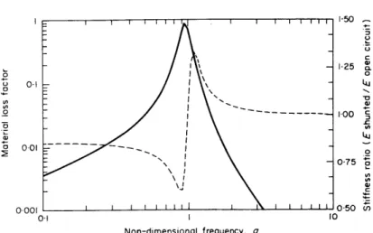
o, = /LiCS i = electrical resonant frequency. (7) The loss factor and relative modulus equations have been plotted versus g, the dimensionless frequency in Figure 5 for a typical value of the coupling coefficient. As illustrated by figure 13, peak loss factors close to 100% are possible. It should also be noted that the stiffness of the piezoelectric changes drastically from its short circuit value at low frequencies to its open circuit value at high frequencies. This stiffness jump at g = 1, does not lend itself to the simple optimization techniques used in resistive shunting. Transfer function techniques described completely in reference 3, must be used instead. Sizing the LRC circuit for the smart joint and six-axis damping designs described in the next chapter, yielded 15kH, and 0.4kH inductors, respectively. Inductors as large as these must be simulated with the active inductor techniques described in reference [3]. Despite the feasibility of this design, resonant circuit damping of discrete modes was not investigated any further. Instead, this research focuses on using broadband damping to facilitate the control of these discrete modes.
~ i I I I i I I 1 . I I I I III ,0 1,25 o o 0.1 LU 075 0.001 050 0-I 10 Non-dimensional frequency, g
Figure 14. Effective material properties of piezoceramic shunted by a resonant LRC circuit (r = 0.20) in the transverse mode of operation (k33=0.38) showing material loss
factor (solid) and relative modulus (dash). Reference [3].
1.4.4. COUPLING SHUNTED PIEZOELECTRICS TO STRUCTURES
The peak loss factor of a vibration will decrease from that of the piezoelectric, when it is coupled to its host structure, according to the fraction of the total strain energy that is actually in the piezoelectric, reference [3]
77 = l U Us, (8)
where Ui is the strain energy in the ith element of the structure. The challenge is thus to employ the damping piezoelectric material in areas of high strain energy to take advantage of this weighting. Of course, the high strain energy locations must also be ranked by their influence on system performance objectives.
The strain energy sharing concept is first considered when designing the damper to be applied to the structure. Note that the word, damper, refers to the piezoelectric damping material and any necessary series or parallel stiffnesses that give the device structural integrity. All damping devices can be simplified to follow one of two different design procedures:
Case(l) If the damper is made up of 100% piezoelectric that is loaded in one direction the material properties in figure 12 apply. An example of this is a shear washer to be discussed in section 2.1. In this case, the appropriate resistor moves the peak of the component loss factor to the desired frequency:
p = RC = 1- k2 (9)
Case(2) If the damper consists of a piezoelectric with series and/or parallel stiffnesses, the peak loss factor location can no longer be guided by equation (9). In this case, equation (9) is a good first iteration approximation if series stiffnesses are high and parallel stiffnesses are low compared to the piezoelectric. The short circuit stiffness, K, and the open circuit stiffness, (K, + K2) must be computed from an analytical or finite element
model of the complete device. Assuming the component's effective material properties are analogous to the piezoelectric, a first order estimate of the effective coupling coefficient,
1- K2 = K' (10)
Kcomponet
is then used in (9) in place of k? to size the resistor. An example of this is the flex-tensional device described in section 2.2.
Regardless of the design case, the short and open circuit stiffnesses of the damper determine two of the minimum three points necessary to describe the first-order stiffness curve of the damper (figure 15(a)). The third parameter, conveniently given by the transition frequency, p, is determined by the value of the shunting resistor.
1.4.4. FINITE ELEMENT MODELING OF PIEZOELECTRIC-BASED DAMPERS
In order to determine the performance of a given piezoelectric damping scheme in its host structure, the damper's stiffness and loss factor curves from figure 6(a) must be modeled. This behavior is captured by the following spring and dashpot finite element configuration (figure 15(b)).
I
T I .I..I.I I II _(K,
+ K,) ///////IKI K,
C
Figure 15. (a) Effective damper properties of a resistively shunted piezoelectric damper in the longitudinal case (k33=0.75) showing damper loss factor (solid) and the
The complex stiffness of the three element configuration is modeled with two linear spring stiffnesses, K,, K, and one complex dashpot stiffness, Cio as follows:
Keff = K, + I + - (11)
Given K, and K2 from static structural models, C is the only unknown constant needed
to complete the dynamic model. Simple algebraic manipulations yield the appropriate value of C such that the transition from low-frequency short-circuit stiffness to high-frequency open-circuit stiffness occurs at the correct transition high-frequency, p. This is accomplished by arbitrarily selecting a third coordinate point, (w, IIKfII), near the transition of the stiffness curve.
Figure 15 shows an equivalent mechanical model of the resistively-shunted piezoelectric damper (including series and parallel stiffnesses). This mechanical equivalent model is suitable for inclusion in commercial finite element software.
The real and imaginary parts of the complex stiffness are separated in (12) to calculate the real magnitude in (13):
Keff = KKK22 + (C) 2 (K, + K2) ( K2 )K (12)
K2 + (Co)2 K2 + (Co)2,
IKeffiI
= [Real(Keff )] + [Imag(Keff )]2 (13)The results of (10) are manipulated into the quadratic equation, C' {a,} + C2 {a,}+ {a,} = 0 and solved for the only unknown, C.
C4 *4[(K, + K2 )2 - (IKeff)2
11
+C {o2[2KIK2(K, + K2) +K 14- 2(IKeffI)2 K22} +
K(K - 2
)=
0(IKeff11)0 (14)This equivalent mechanical model is used in Chapter five to generate the simulated performance transfer functions of the piezoelectric-based component.
CHAPTER 2
POTENTIAL PIEZOELECTRIC DAMPING
IMPLEMENTATIONS FOR ASTREX
The general problem of damping a complicated space structure with piezoelectric materials is open-ended. In trusses consisting of repetitious truss bays the problem is to optimize strut placement, in order to maximize the percentage of strain energy in the damping elements. In structures, like ASTREX, which consists of tripod legs and a hexagonal-planar truss, the options are more numerous for placing various damping elements in various locations. There is freedom to use any device that has considerable influence in damping the modes that facilitate control rolloff.
The most obvious damping scheme, building struts for ASTREX, was not considered for the following two reasons: 1. It was determined in reference 2 that replacing ASTREX's primary composite struts with piezoelectric struts offers insignificant damping with only a few struts being switched. Obviously, if too many struts are replaced, the structure becomes too heavy. 2. Laminated piezoelectric/composite active struts made by TRW, which replaced the three tripod legs, have already been installed in the testbed. Prior to their installation, full-length piezoelectric-composite tripod struts of figure 16, would have been considered for manufacture. This implementation would replace a fraction of the tripod composite tubing with three equally spaced piezoelectric stacks (nine meters long, one inch diameter), such that the axial and bending stiffnesses were unaltered.
Two alternative damping schemes were considered. The "smart-node", active-joint or piezoelectric washer is addressed in section 2.1. The six-axis proof mass damper with
piezoelectric actuators is addressed in section 2.2. These devices are ranked in section 2.3 according to their loss factor potential.
Piezoelectric Stacks
Composite Tubing
Figure 16. Proposed Piezoelectric-composite tripod strut with three equally spaced piezoelectric stacks (three meter version). Tripod length is nine meters.
2.1. POTENTIAL DAMPING DEVICE: SMART JOINT
An inexpensive and lightweight alternative to building full-length piezoelectric tripod struts is the tripod rotational damper, or "smart joint". The objective of this device is to damp the first two or three bending modes of the tripod fixture. Previous analysis in reference [2], has determined that the low-frequency tripod bending modes are critical to the line-of-sight performance. Therefore, the design issues of having a rotational damping mechanism at each of the three tripod-to-backplane mounts was investigated.
Damping rotational motion can be accomplished with piezoelectric washers, sleeves or equivalent struts. Each of these designs will be assessed later. First, it is necessary to determine the rotational stiffness, Krot in figure 17, that leads to maximum strain energy in the rotary spring, for the first and second bending modes (that occur at roughly 20 and 60Hz). Recall that a peak damping target frequency near 40Hz was selected to best enable feedback control.
The quickest way to find the optimal stiffness of the rotational damper, is to use the assumed modes method on a simple model of the essential deformation in ASTREX at low frequencies; namely the spring-mass-tripod leg model of figure 17.
"Smart
o Joint" EI, L Apex
(0)Figure 17. Tripod bending: The essential low frequency ASTREX dynamics.
Calculating the piezoelectric strain energy fraction with an assumed first-bending mode shape for the tripod leg, co(x) = sin(nx/L), yields:
1
2 1 Ube = f El 2c dx - El - L. (15) =2 o x (4 L Urt =2 2 L
1K,(0(0))2 =1Kro, -r (16) Uro' = 1+ --EI ' , (17) Utota 2LKrotThe variables, U,,, Ub,. and Uo are the strain energies of the rotary damper, the tripod leg and their sum, respectively. For example, when the strain-energy fraction is ten percent (typical value from other ASTREX analyses), an initial estimate for the rotational stiffness is: Km, = 0.5 EI/L.
A less quick, but more accurate method is to use the dynamic finite element model shown in figure 18. The goal is to maximize the piezoelectric strain energy in the first or second bending modes. This can be evaluated using the ratio:
piezo iezo pieo, (18)
Since the piezoelectric's rotary stiffness is in series with its deformable channel interface with the backplane truss (see figure 7), the modal displacements of the rotary damper must be scaled by the ratio of piezoelectric flexibility to total rotary flexibility, a.
piezo =a(,)ro; a
CKn
+ K
rKcneK rpez (19)
where, Krot = - + (19)
piezo channel
Mode2 0.5 Mapex
The optimal stiffness value of 400kNm agrees with the optimal value obtained by iterating the stiffness in the full-scale ASTREX finite element model until the piezoelectric strain energy peaks near 40Hz (the mean frequency between the first two bending modes). This indicates that it is safe to assume that most of the total strain energy at low frequencies is in the tripod legs, not the backplane truss. NASTRAN also indicates that the piezoelectric absorbs 10% of the total strain energy (4.2% modeled loss factor) for a typical tripod bending mode at 29Hz. The optimal stiffness can now be used to design and assess three different rotational dampers: the washer, the sleeve, and the equivalent strut.
2.1.1. PIEZOELECTRIC WASHER DESIGN
The washer design consists of piezoelectric material that is strained in shear under dynamic loading. As the tripod leg bends it exerts a reaction torque at the tripod mount, which behaves as a fixed boundary condition. Inserting piezoelectric washers between the ears of the tripod strut and the clamps of the mount, transforms the rigid boundary condition into a rotary spring as seen in figure 19.
Insert PZT washers here
Figure 19. Piezoelectric "washer" design for tripod strut joints. Two washers per strut are each loaded in the shear mode.
Using the optimal stiffness in the shear stiffness equation (6), a washer with a one inch outer diameter with a half-inch hole and one-eighth inch thickness is calculated.
GJ G ( (d4 (20)
where J is the polar moment of inertia of a disk and the shear modulus is, G = 26GPa for Ch-5400 piezoelectric material (short-circuit).
After the washer's size was determined acceptable, the feasibility of shunting circuits for the piezoelectric dimensions must also be determined. Sizing the inductor, L, and resistor, R, for resonant circuit shunting according to the formulations described in chapter 1, yields: L = 15kH and R = 1000kW. For resistive shunting, a resistor, R = 1490kM, is ideal. Both of these resistors are accessible. The inductors, however, would be heavier and larger than the actual testbed itself, unless an active inductor scheme described in chapter one was used. Despite the feasibility of the resonant circuit, the broadband damping of resistive shunting was used for the sake of controller gain stabilization.
2.1.2. PIEZOELECTRIC WASHER MANUFACTURING ISSUES
Once the washer's dimensions and shunting network has been sized and determined feasible, the piezoelectric poling issues must be addressed. Manufacturing the washers would involve inventing a feasible means to accomplish circumferencial poling of a disk. Two methods were investigated: magnetic field poling and continuous sweep poling.
XX X XXX x x xR X XXX X X XE x x x X X X X-- X X X SXX X XX
Figure 20. Circumferencial poling technique using a rapid change in magnetic field, (B: out of page "x") to produce a circumferencial electric field, E.
The feasibility of magnetic field poling was evaluated with the electromagnetic relation in equation (21), which states that the line integral of the electric field is equal to the change in magnetic flux within that integral path, 0B = B&r".
Ef - (21)
For r < R, and a required polarization voltage of 38kV/cm, the required magnetic field rate of 3000 gigagauss/s is too high to create even with an instantaneous step input.
Bq I =- Ereq'd = 3 0 0 0 gigagauss (22)
Oreq'd r rd
An alternative poling scheme is a continuous circumferencial poling scheme adapted from reference [20]. This poling technique rotates the washers slowly through two flexible surface electrode pairs maintained at the required potential difference (figure 21).. As the electrodes sweep the sides of the washer, the piezoelectric gets poled a full revolution in one hour: a rate sufficient to pole the piezoelectric material. This rate, 0o= 6deg/minute was adapted from the experimental recommendations in reference [20]. The flux field described by equation (23) reference [20], decreases in intensity as the distance into the piezoelectric, r, is increased. a 0.254 -....# \ 4mm---r 0.5' E Electrodes
Figure 21. Continuous circumferencial poling of the washer. a3
E' (x) = EapUed (a2 + 2 1. (23)
From equation 23, the poling voltage across the electrodes must be applied to both sides of the piezoelectric in order to generate the same voltage in the center of the one-eighth inch thick washer. The applied poling voltage of 40kV/cm can be increased with electrode separation until the electrodes are separated by a 4mm gap. If the gap is increased still further, the required applied voltage can no longer be generated with a 10kV power supply (reference [20]). Figure 22 shows that the total electric field remains relatively constant if the electrode pairs are placed symmetric about the piezoelectric. This poling procedure would require the development of a circumferential poling machine. Such a task is out of the scope for this project.
Cross-sectional Electric Field Distribution 100
20
0 1/32" 1/16" 3/32" 1/8" Distance from Electrode: r (inches)
Figure 22. Continuous washer poling electric field distribution.
2.1.3. PIEZOELECTRIC WASHER STRESS ANALYSIS
Static and dynamic stresses were computed from NASTRAN finite element program and then used to evaluate the washer's load capability. Static stresses were computed from a NASTRAN model of ASTREX in its 30 degree position. Static stresses of 5.9MPa were calculated. This stress was conservatively assumed to be taken by the washers, not the tripod bolt that actually takes the load of the attached tripod structure. Torquer input to piezoelectric displacement transfer function output over the first 100Hz was calculated and scaled by the reaction wheel's maximum apex torque of 37Nm, to find the maximum dynamic stresses. The maximum dynamic stress in the piezoelectric washer is:
zmx GOmaxr = 104MPa, t (24)
where the shear modulus is, G = 26GPa, the maximum rotary displacement is, O8m x = 10001radians, the outer radius is, r = 1 / 2inch, and the thickness is, t = 1 / 8inch.
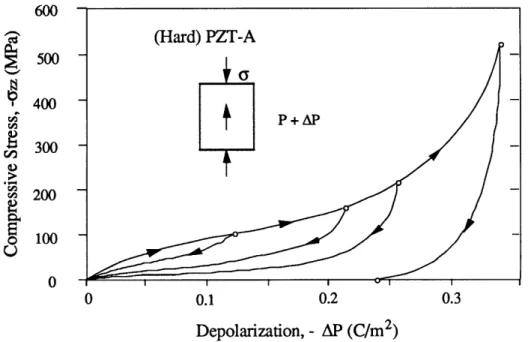
In order to maintain a factor of safety near three times brittle fracture, and avoid permanent depolarization in the piezoelectric, the piezoelectric design stress limit of 50MPa
was enforced. The 50MPa limit also ensures that the loss factor does not taper off at high stresses as seen in figure 23.
600 500 400 300 200 100 0 0.1 0.2 0.3 Depolarization, - AP (C/m2)
Figure 23. Percent depolarization versus applied stress in MPa for PZT Ch-5400. Note the permanent depolarization hysterisis loop.
For the washer, unlike the six-axis tuned-mass damper in section 2.2, there is no practical way to provide a mechanical stop to prevent excessive rotary motion directly. Instead a rigid mechanical stop would be required to impact with the tripod's 0.3mm displacement at a ifoot distance from the pivot point. In short, the mass penalty of the mechanical stop would be larger than the damping mechanism itself. When modes skew to the plane of the washer are considered, the non-planar tensile stresses in the piezoelectric must also be constrained. This would demand even more bulk from the prospective mechanical stop in order to constrain the tripod in three dimensions.
In conclusion, the inelegance of the mechanical stop and the overwhelming labor involved in circumferential poling, discontinued the piezoelectric washer design.
2.1.4. ALTERNATIVE "SMART JOINT" DESIGNS
This section will briefly assess two alternative "smart joint" designs that have equivalent dynamic properties as the piezoelectric washer, but different manufacturing problems. The preliminary assessment has indicated that the piezoelectric sleeve of figure 24 and the equivalent piezoelectric strut of figure 25 are difficult to manufacture.
The sleeve design in figure 24 is similar to the washer in that both designs use circumferentially poled cylinders or disks as the damping element. The sleeve, however, is sheared against the tripod's axel and through the radius of the cylinder, whereas the washer is sheared through the thickness of the disk. Also, the sleeve's electrodes are placed on the inside and outside cylindrical surfaces, as opposed to both sides of the disk.
Sizing the component according to elasticity equation for a thick-walled cylinder derived in reference [21],
Ko = 400kNm = 47rGL r 0 (25)
r0, -ri,
yields the following sleeve dimensions: r., = 0.25", r., = 0.5", and L = 0.9".
Poling
Touter
Torqw Tripod Strut Tine Bolt .rt d - Piezo Bearing SleaveFigure 24. The sleeve is poled in the radial direction to exploit the shear mode of piezoelectric damping.
In addition to circumferential piezoelectric poling, the sleeve damper would also require a new tripod strut mount to accommodate the larger piezoelectric's length (L = 0.9"). With the washer design, the fixed boundary condition on both sides of the disk is ensured by preloading or tightening the bolt. The sleeve, however, has no preloading mechanism. Glue layers, that bond the inner surface to the tripod bolt and the outer surface to a modified tripod-end piece, would unfortunately absorb strain energy that could be used to actuate the piezoelectric. Shearing electrode surfaces could also present more difficulty over the easily accessible piezoelectric washers. Thus, the device was discontinued.
For a given washer or sleeve there exists an equivalent piezoelectric strut, orthogonal to the tripod strut, and separated from the tripod bolt by distance r. The strut's dimensions, A and L, and moment arm, r, are sized with the equivalent stiffness equation (26).
Tripod Strut /
Figure 25. The equivalent piezoelectric strut. GJ EA 2
-= -r . (26)
t L
When the 400kNm stiffness is substituted into Equation (26) the optimal strut dimensions are: diameter = 0.5" and L = 5.2" for a moment arm r =3". Poling the device in the 3-3 direction is simplified by gluing wafers in series to form a stack with minimal electric field flux loss. The buckling loads on such a slender strut would require the design of high bending stiffness reinforcement with negligible axial contribution.
2.2. POTENTIAL DAMPING DEVICE: SIX-AXIS VIBRATION ABSORBER
The six-axis proof mass vibration absorber with six piezoelectric dampers was born out of the need to create an energy sink for the heavy (90kg) apex mass undergoing large displacements. Displacements over 4 times those found in the back plane, have been determined from ASTREX's eigenvectors. Preliminary finite element analysis of the six-axis stewart platform configuration indicated that an effective damper stiffness of 1.5N/um would channel over 50% of the total strain energy in the piezoelectric material for several modes under 50Hz. Theoretically, this means that modal loss factors as high as 20% are attainable. Mode shapes and loss factors that are representative of their corresponding frequency region, are shown in figure 27 in the next section.
The six-axis proof mass damper design in figure 26 consists of an already existing 90kg. balancing mass suspended from the interior of the 24"x24"x24" triangular apex housing by six flex-tensional damping devices. It should be noted that the 90kg. mass primary purpose is to balance the ASTREX testbed on its air bearing ball joint. The ball joint is connected to the center of the hexagonal primary truss which is elevated above the floor by a twenty foot supporting post.
The Stewart bridge configuration yields the maximum stroke capability available to the six axis damper design. This optimal stroke/actuation configuration was slightly modified to accommodate the geometrical constraints of the congested apex interior. (see figure 26) If the distance, d, between adjacent struts in each of the three orthogonal strut pairs is decreased, the rotational eigenvalues of the proof mass decrease due to the decrease in the system's effective moment arm. This yields a more effective damper for the low frequency rotary movements. The tradeoff is the increase in static stresses of the dampers due to gravity loads. The distance versus stress optimization for the modified Stewart bridge was not investigated, since the dimensions of the damping device prevented the aforementioned distance reduction.
90kg.
Figure 26. (a) Apex. (b) Six-axis vibration absorber with 90kg. proof mass attached to apex housing interior by 6 piezoelectric-based damper/actuators.
The applied static and dynamic component forces need to be determined before the actual piezoelectric and component properties can be determined. The total force will be used in chapter 3 to calculate component stresses. The static forces applied to each component are each dependent on the orientation of ASTREX. For this application it is important to design each component for the maximum force induced by static gravity loads and dynamic operating loads. In order to accomplish this and keep the piezoelectric in compression under dynamic loads, preload stresses in excess of the 50MPa design limit are required. In the laboratory, however, each of six actuators can be preloaded separately according to the total static and dynamic applied force. If too much preload is used the
piezoelectric may depole. If too little preload is used, the piezoelectric may fail as soon as the device flexes in tension as in equation 27.
O <
o,,a,
5 a , = 50MPa (27) Multiplying the peak strut displacement on the torquer to strut transfer function by the maximum operating torque of 37.5Nm, yields the dynamic force in the six components of 275N. When ASTREX is in its 30 degree laboratory configuration, the six axis has the following static strut forces: The top two struts are in 900N tension, the lower strut pairs are in 600N compression. Maintaining an approximate 10% factor of safety for the loading, the top struts need to be designed with 1300N of tension (piezoelectric compression), and the lower strut pairs need to be designed with 1000N of compression (piezoelectric tension). The best device, as designed in chapter 3, will have adjustable tensile and compressive preload capability. For instance, the lower strut pairs will need compressed preload springs to avoid piezoelectric tension, while the top struts will need a preload spring in tension to avoid piezoelectric depolarization.After the preliminary device design and piezoelectric size was determined acceptable, the feasibility of shunting circuits for the piezoelectric dimensions must also be determined. Sizing the inductor, L, and resistor, R, for resonant circuit shunting according to the formulations described in chapter 1, yields: L = 0.4kH, R = 700ka and C = 6.8pF (inherent piezoelectric capacitance). For resistive shunting, a resistor, R = 917kQ, is ideal. Although the resistors are accessible, the inductors would weigh 300g, unless an active inductor scheme described in chapter one was used. Despite the feasibility of the resonant circuit, the broadband damping of resistive shunting was used for the sake of controller gain stabilization.
2.3. DAMPING PERFORMANCE: SMART JOINT VERSUS SIX-AXIS ABSORBER In order to decide which damping scheme to attempt to build, the two designs were evaluated according to their ability to absorb strain energy from performance-sensitive modes. Recall equation (5), that states that the system loss factor is proportional to the fraction of the total strain energy in the piezoelectric for a given mode. Although only three modes are listed in figure 27, the trend of six-axis vibration absorber dominance is present in all modes. The potential merit of the six-axis absorber obviously exceeds that of the washer design. In the next chapter the design of the six-axis absorber and component is presented.
Mode #13 f = 29Hz 1,,, =19.4%
rwahers
=4.2%
Mode #23 f = 42Hz q6axis, =7.2% rlws,h,, =0.042% Mode #40 f = 77Hz q2axi, =0.42% qw7a,h,, =0.008%CHAPTER 3
DESIGN AND ANALYSIS OF THE
FLEX-TENSIONAL COMPONENT
The most critical part of six-axis proof mass damper design, described in chapter 2, is the component design of the six damping devices. The device design is complicated by the fact that piezoelectric material alone is too stiff and brittle to be used as a low-frequency damper. It is desirable to tune the vibration absorber to 30Hz. A 30Hz tuned vibration absorber will sag about 250micrometers in a one-gee field. This deflection implies a material strain for greater than the ceramic will allow. Thus, a properly designed stroke amplification device is essential in reducing the device's stiffness and increasing its travel.
2
Figure 28. Illustration of the prototype flex-tensional piezoelectric stroke amplification device. Parts include: 1. One 16-layer piezoelectric stack with two steel shims. 2. One steel flex-tensional stroke amplifier. 3. Two preload springs. 4. Two threaded steel rods with adjustable mechanical stops. 5. Axial stinger.
3.1. DESIGN DETAILS OF THE FLEX-TENSIONAL DEVICE
The role of each of the five parts described in figure 28 and their associated design, manufacturing and assembly considerations will be assessed in the following five paragraphs:
Design Feature #1: The role of the piezoelectric stack is to provide resistively-shunted passive damping. The design uses mechanical amplification to reduce the stiffness of the stack in order to meet the 30Hz target eigen-frequency of the six-axis tuned mass damper. This, in turn, creates large critical stresses in the piezoelectric. Reducing the stack's stiffness may also be achieved by increasing its length and decreasing its cross-sectional area. This design is limited by a requirement that the material stresses are no greater than 50MPa. This requirement ensures minimal performance loss due to hysteretic depolarization. Buckling and shear failure must also be considered for slender stacks.
Another design consideration for the piezoelectric material is to have the appropriate number of capacitors (stacks) to balance the trade-off between glue-layer strain energy loss and large capacitor thickness fringing field loss. The glue layers between the 16 wafers act as springs in series with piezoelectric. A 16-wafer piezoelectric stack was the engineering judgment. The glue-layers gave the piezoelectric stack a longitudinal coupling-coefficient,
k3 3, of 0.59 as opposed to the nominal material value of 0.71. This reduces the available
piezoelectric peak loss factor from 35% to 21% as given by equation (5), chapter 1.
Design Feature #2: The role of the steel flex-tensional stroke amplifier is to provide the necessary amplification to give the piezoelectric structural integrity and low stiffness. Stroke amplification in the device equates to a strain reduction in the piezoelectric. The ideal stroke amplifier would consist of beams with infinite axial stiffness connected by perfect hinges so that all the component's strain energy would be concentrated in the piezoelectric stack. This maximizes the peak component loss factor. A realistic component, however, has the following design criteria: 1. The lever angle is selected according to the analytical model, equation (49), so that the desired effective stiffness is realized. 2. The sum of the axial stiffness of the flexures is much greater than that of the stack. 3. The bending stiffness of the flexures is much less than that of the component. 4. The flexure stresses are less than their respective yield stresses. To meet these requirements, the stroke amplification device consists of a monolithic piece of steel, which is carved out of quenched and tempered 40 Rockwell steel by a machining process called: wire Electron Discharge Machining (wire-EDM).
Design Feature #3: The role of the two preload springs is to ensure that the piezoelectric stack remains in compression under normal loading conditions. This also keeps the flexures in tension. The optimal design for the spring is a mile high spring with
negligible stiffness. When such a combination is squeezed into the device, the preload requirement is met with negligible device stiffness contribution. Such a spring is limited by practical assembly procedures which require pronged pliers insertion to shorten the spring temporarily for insertion into the EDM'ed part. Spring coil spacing must be large enough to allow for a wrench adjustment of the mechanical stops.
Design Feature #4: The two mechanical stops are adjusted to prevent accidental overloading of the device. The maximum disturbance excitation of 28 ft.lbs. plus gravity load yields the component's maximum axial displacement of 0.3mm. Motion in excess of this number is inhibited. The mechanical stops are adjusted by wrench and locked in place with adjacent locknuts.
Design Feature #5: The role of the axial stinger is to suspend the 90kg. mass according to the modified Stewart bridge configuration. High axial stiffness and low bending stiffness of the stinger minimizes strain energy sharing. Low bending stiffnesses can be obtained by using a pinned flexure at each end of the stinger.
3.2. DEVICE ANALYSIS: ANALYTICAL TRUSS MODEL
Three different methods were investigated in designing the component. In this section, a simple truss analytical model is useful for preliminary design purposes. A NASTRAN finite element model, presented in 3.3.1, accounts for all stiffnesses. This model is upgraded in Section 3.3.2 to include the unmodeled flexibilities. In Section 3.3.3, the finite element model is used to optimize the component design.
3.2.1. KINEMATIC DERIVATION OF EFFECTIVE STIFFNESS
If it is assumed that the bending effects contribute negligible stiffness, the effective stiffness of the mount is easily determined through simple kinematics employing linearization for small displacements. Referring to figure 30, the vertical and horizontal displacements of each element are related as
8, = 2L, sin(0) - 2(L, - 8,)sin(9 - 80) (28) L + 8h = (L - 8) cos(9 - S0), (29)
where the kinematic constraint ensures that the elements remain connected during displacement.


![Figure 8. Piezoelectric truss member used in the space structure of reference [3].](https://thumb-eu.123doks.com/thumbv2/123doknet/14687966.560603/15.918.141.767.483.758/figure-piezoelectric-truss-member-used-space-structure-reference.webp)