HAL Id: hal-00976949
https://hal.archives-ouvertes.fr/hal-00976949
Submitted on 10 Apr 2014
HAL is a multi-disciplinary open access
archive for the deposit and dissemination of
sci-entific research documents, whether they are
pub-lished or not. The documents may come from
teaching and research institutions in France or
abroad, or from public or private research centers.
L’archive ouverte pluridisciplinaire HAL, est
destinée au dépôt et à la diffusion de documents
scientifiques de niveau recherche, publiés ou non,
émanant des établissements d’enseignement et de
recherche français ou étrangers, des laboratoires
publics ou privés.
Sizing optimization of piezoelectric smart structures
with meta-modeling techniques for dynamic applications
Valérie Pommier-Budinger, Marc Budinger
To cite this version:
Valérie Pommier-Budinger, Marc Budinger. Sizing optimization of piezoelectric smart structures with
meta-modeling techniques for dynamic applications. International Journal of Applied
Electromagnet-ics and MechanElectromagnet-ics, IOS Press 2014, �10.3233/JAE-141771�. �hal-00976949�
This is an author-deposited version published in:
http://oatao.univ-toulouse.fr/
Eprints ID: 11332
To link to this article: DOI:
10.3233/JAE-141771
URL:
http://iospress.metapress.com/content/m701l4q7354g1638/
To cite this version:
Pommier-Budinger, Valérie and Budinger, Marc
Sizing optimization of piezoelectric smart structures with meta-modeling
techniques for dynamic applications. (2014) International Journal of
Applied Electromagnetics and Mechanics. ISSN 1875-8800
O
pen
A
rchive
T
oulouse
A
rchive
O
uverte (
OATAO
)
OATAO is an open access repository that collects the work of Toulouse researchers and
makes it freely available over the web where possible.
Sizing optimization of piezoelectric smart structures
with meta-modeling techniques for dynamic
applications
VALERIE POMMIER-BUDINGER1, MARC BUDINGER2
1
corresponding author
Université de Toulouse, Institut Supérieur de l’Aéronautique et de l’Espace, France 10 avenue Edouard Belin, 31055 Toulouse, France – Tel : 00 33 (0)5 61 33 91 20 e-mail : [email protected]
2
Université de Toulouse, Institut National des Sciences Appliquées, Institut Clément Ader, France
Abstract
This article shows an efficient method with a high industrial applicability to design piezoelectric smart structures for dynamic applications. This method allows sizing structures with requirements of dynamic displacements. The first step of this method consists in extracting dynamic reduced models from Finite Element simulations which will enable us to obtain a model for any structure, whatever its complexity, as opposed to analytical modeling methods. These models are computed for a set of design parameters. Then a meta-model, which is a simplified descriptive model of other models, is computed as a surface response model that expresses the design objectives and constraints as a function of the design variables. The combination of the results stemming from the meta-model allows working out the optimal values of the design parameters. The main advantage of the proposed method is to enable the quick design exploration of structures. As an example, the method is applied to a flexible structure whose dynamic displacements need to be controlled in bending and twisting. The theoretical results are validated in the end by experiments.
Key words
1. INTRODUCTION
Piezoelectric smart structures, the association of structures with piezoelectric devices (ceramics, PVDF or piezocomposite), are the subject of a very large number of studies. One of the issues these studies present lies in the design of such structures to improve performance or to obtain the required specifications. This design can be seen as a succession of several steps:
- The optimization of the piezoelectric actuators (types, sizes, locations on the structures…) - The model of the structure to control
- The design of the control law
In this paper, we will deal with the first step only, and even with this restriction, the number of studies remains really high. For the state of the art, we mainly refer to articles published these last ten years. The readers who would like to get an overview of previous articles can refer to Frecker [1] who has conducted a review on the optimization of smart structures and actuators and to Chee et al. [2] who have studied the modelling of piezoelectric sensors and actuators incorporated in intelligent structures. In order to help the analysis of the papers regarding optimization, we have chosen to classify them according to several criteria which are defined as follows:
- the optimization methodology: sizing optimization (the shape of the actuators is set and the design variables are sizes (e.g. the length and the width for a rectangular piezoelectric ceramic), shape optimization (the shape can change but not the number of boundaries) or topology design (the number of boundaries and the shape of the actuators can change).
- the objectives and constraints of the optimization: required displacements, maximum electromechanical coupling factors (EMCC), maximum controllability, maximum observability, minimum weight, required supply voltage…
- the type of applications: static or dynamic
- the type of analysis used to solve the problem: analytical or Finite Element analysis
The first set of studies we have analyzed deals with sizing and shape optimization. In 2002, Mukherjee et al. [3] offered a method to optimize piezoelectric structures based on the minimization of the global displacement residual error between the desired and current structural configuration. The structure was discretized but all the computations were analytical and the case studies dealt with a beam in static and dynamic configurations. In 2003, Irschick et al. [4] achieved dynamic shape control with a method to
compute the spatial distribution of piezoelectric actuators that allows getting a structural displacement field. This analytical method was applied to composite beam-type structures. Then, Sun et al. [5] used an energy optimization based method to find the optimal control voltages which can actuate a structure close to the desired shape within a given error. They applied the method on a static case for the shape control of composite plates. Nguyen et al. [6] also proposed a design method for static cases. They studied the shape control of plates by using a method based on a multi-criteria optimization. Later, Donoso et al. [7] considered optimal design problems in the context of active damping, more specifically to control the deflection of a structure subjected to static and dynamic loads. The optimal thicknesses or widths of the piezoelectric ceramics minimizing the deflection were computed thanks to an analytical analysis. The method was thus applied to a simple cantilever beam. Another study of Donoso et al. [8] extended the same analytical method to rectangular plates. At the same time, Zhang J. et al. [9] computed the optimal locations and sizes of piezoelectric actuators to produce the maximum controllability and observability of modes in smart structures. In their paper, the model of piezoelectric smart structures is built by the application of Finite Element software and the study is performed on a dynamic case but with no specification on the displacement amplitudes whatsoever. Zhang R. et al. [10] also studied the optimal location of piezoelectric actuators in case of uncertainties. Recently, Brusa [11] proposed the optimization of a hybrid energy scavenger. Although, once again, concerning the shaping of the surface of the cantilever, the optimization was based on an analytical expression of the normal stress.
Another trend for the design of piezoelectric smart structures is the use of topology optimization based on finite element analysis and optimization techniques such as the method of moving asymptotes, genetic algorithms, optimality criteria method, … It allows computing the topology of piezoelectric patches in order to maximize or minimize a physical quantity such as compliance (external work), stress, electromechanical coupling factor, etc... Kögl et al. [12] used topology to design piezoelectric plates and shell actuators in static applications. Carbonari et al. [13] applied topology optimization to find the optimum gradation and polarization sign variation in piezoceramic domains in order to improve bimorph-type actuators. In this study, the performance was measured in terms of static output displacements. Drenckham et al. [14] investigated the optimal topology of a piezoelectric actuator to reduce the tip deflection of a static cantilever beam under a concentrated tip load. Rupp et al. [15] used topology
optimization to design the layout of a multilayer structure to maximize the harvested power. The particularity of this work was to design the layout of piezoelectric and structural materials on layered plate structures as well as the harvesting circuit to which it is connected. Zheng et al. [16] designed energy harvesting devices in static cases by considering both the locations of piezoelectric patches and the elastic layout of the structures. The more recent works address the design of piezoelectric actuators, sensors and energy harvesters on static structural problems (Kim et al. [17]), the dynamic design of piezoelectric laminated sensors and actuators to obtain specified resonance frequencies, modes and electromechanical coupling factor (Nakasone et al [18]), the static shape control of piezoelectric plates (Kang et al. [19]), strain energy–based finite element approach (Bachmann et al. [20]) and the design of piezoelectric energy harvester using stress norm constraints (Wein et al [21]).
Our work tackles the sizing optimization of piezoelectric smart structures for dynamic applications and the method that we propose is based on the response surface methodology
(Park et al. [22], Choi et al.
[23]) and on
the analysis of a meta-model consisting in an analytical model derived from reduceddynamic models obtained from Finite Element results. In our study, the sizing aims at getting required displacements with a minimal volume of piezoelectric patches. The meta-model is thus composed of polynomial functions expressing the dynamic displacements of the structure as a function of the piezoelectric actuators’ dimensions. These displacements are worked out from a set of reduced dynamic models selected by a Design of Experiment (DoE) and obtained by Finite Element software which allow us to study more complex structures than beams or plates. The main advantage of meta-modeling techniques is that they enable to compute a design model from a finite and limited number of Finite Element simulations that are time-consuming. As a consequence, they enable quick design exploration of structures.
The above cited articles proposed studies with some similarities but neither with the same objectives nor the same methodology as the one we are developing here. As far as we know, the examples of studies using meta-modeling techniques to design piezoelectric structures (Cappelleri et al. [24] and Paternoster et al. [25]) only addressed optimization of static forces and deflections. For dynamic applications, the objective functions or constraints of the common methods which tackle the design issue are the required resonance frequencies, modes or enhanced electromechanical coupling factors because these values are
easy to compute. We have chosen to use the dynamic displacements, even if their computation is not immediate and requires intermediate calculations, because they are significant values in dynamics problems. Furthermore, let’s also point out that vibrations control can be achieved by the use of semi-passive (Guyomar et al. [26]) or semi-passive (Irschik et al. [27], Porfiri et al. [28, 29], Shen et al.[30]) solutions and that our method relates to active solutions. Therefore, in addition to vibration control, it can be used for the generation of vibrations (e.g. for ultrasonics transducers).
The novelty of our article is to combine Finite Element simulations, computations of reduced dynamic models and meta-modeling techniques to design actively controlled smart piezoelectric structures which meet requirements in terms of dynamic displacements.
Section 2 presents the smart piezoelectric structure under study with the design variables, the reduced dynamic model computed from Finite Element simulations and its use to compute the dynamic displacements of the structure. Section 3 deals with the meta-modeling techniques. Section 4 gives the meta-model obtained from the responses (output variables) and the results of the sizing. Experimental tests validate the study.
2. THE STRUCTURE UNDER STUDY AND ITS REDUCED DYNAMIC MODEL
2.1. Description of the structure
The structure under study (Fig. 1) is made of a plate in aluminum alloy and a cylindrical tank in PVC whose characteristics are given in table 1. The plate is clamped at one extremity and free at the other, where the tank is attached to the plate thanks to a metallic ring. The structure has been designed to have low resonance frequencies as an aircraft wing and to study robust control laws to attenuate vibrations in bending and twisting, whatever the filling of the tank. The design study is carried out in this article for the case of an empty tank, not to deal with sloshing phenomena which would introduce other resonance frequencies than the frequencies of the single plate. However, even if it is not developed here, our method is also valid for the cases with liquid in the tank.
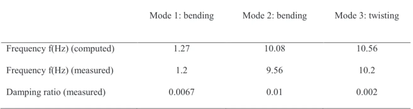
A Finite Element Analysis is performed to compute the first resonance frequencies of the structure and a modal testing allows measuring the damping ratio associated to these frequencies. The results are given in Table 2 for the first three modes of the structure. The objective of the control is to attenuate the vibrations
due to these first modes which are preponderant because of their very low frequencies and damping ratios. The requirements are to design a smart piezoelectric structure to control vibrations of 130mm peak to peak for the first bending mode, of 6mm peak to peak for the second bending mode and of 6mm peak to peak for the first twisting mode at the tip of the beam.
(a)
beam tank
Actuators 1&2
(b)
Fig.1. Structure under study (beam with the tank at its tip): (a) picture (b) diagram
Beam Tank Fixation ring
Length (mm) 1360 Ext. Diameter (mm) 110 144.5
Thickness (mm) 5 Length (mm) 500 28.76 Location on beam (mm) 1280 1280 Density (kg/m3) 2970 Density (kg/m3) 1180 2970 Young Modulus (GPa) 75 Young Modulus (GPa) 4.5 75 Table 1. Material and geometric characteristics of the structure
Mode 1: bending Mode 2: bending Mode 3: twisting
Frequency f(Hz) (computed) 1.27 10.08 10.56
Frequency f(Hz) (measured) 1.2 9.56 10.2
Damping ratio (measured) 0.0067 0.01 0.002
Table 2. Dynamic characteristics of the structure
2.2. Design variables
Two sets of piezoelectric ceramics will be used in order to attenuate the vibrations. The piezoelectric ceramics are made of PIC151®PI. They will be bonded at the clamped side of the structure and in the middle of the beam, on each side of the symmetry axis of the beam large side (Fig.2). These locations are chosen to get the maximal strain in the structure for the modes to be controlled and to ensure maximal efficiency of the piezoelectric actuators (Crawley et al. [31]). The design parameters of the study will be the lengths and the widths of the piezoelectric patches (Fig.2). As the problem is symmetric, it is assumed that both patches will have the same length and width. Lengths of the patches L can vary from 30 to 300mm and widths W from 10 to 80mm. The thickness of the patches is not considered as a design parameter because it is imposed by the supply voltage and the maximal electrical field. For this application, the supply voltage is ±120V and as the maximal electrical field is ±400V/mm for dynamic applications, the minimal thickness is 0.3mm. At the end, the patches will be 0.5mm-thick due to supply constraints.
beam tank Point A Point B Actuators 1&2 Length (L) Width (W) uB uA
Fig.2. Design parameters: length and width of the piezoelectric actuators.
2.3. Dynamic reduced model
For the structure under study, the reduced dynamic mode is established for the first three modes. The reduced-model of a structure with k piezoelectric actuators can be modeled for n modes in the modal base with a mechanical equation and an electrical equation as shown in (Hagood et al. [32]) and (Hatch [33]):
+ = + = + + V C q q F V Kq q D q M o T C s e (1) where:
- q is the modal displacement vector (nx1)
- qc is the electrical chargevector (kx1)
- V is the voltage vector (kx1)
- M is the modal mass matrix (nxn)
- D is the modal damping matrix (nxn)
- K is the modal stiffness matrix (nxn)
- θθθθ is the modal electromechanical coupling matrix (nxk) - Co is the modal turned-off capacity matrix (kxk)
- Feis the external forces vector (nx1)
This model can be computed with multiphysics Finite Element software (such as ANSYS© or ABAQUS©) that allows calculations with piezoelectric elements.
The computation of the modal matrices M and K is classical and is achieved through a modal analysis. If the modal base is normalized to the mass matrix, we have:
nxn
I
M = (2)
(3)
where
ω
i are the free vibration angular frequencies.The computation of the matrix is not so common and will be detailed thereafter. We note u(t) the vector composed of the m physical displacements (physical displacement means real displacement on the structure as opposed to modal displacement). Therefore, we can write:
q
u = (4)
where the matrix (mxn) is a matrix of change of basis. can be expressed as:
(5) We construct the matrix such that each column is composed of the m physical displacements computed for each mode j, with j=1..n. With such a matrix and if the piezoelectric patches are short-circuited (potential null on all electrodes, V=0), the electrical equation of system (1) enables to write:
(6)
where is composed of the k electrical charges computed for each mode j, with j=1..n .
With this method, the matrix can thus be computed through the same modal analysis as the one used for the computation of the mass and stiffness matrices provided that the modal analysis is performed with short-circuited piezoelectric patches. The advantage of this method is that you can get the model of piezoelectric structures by executing a single modal analysis.
With regards to the modal damping matrix, it is formulated as (Hasselman[34]):
KM
D=diag(2
ε
i) (7)where εi is the damping ratio of each mode. The damping ratio is generally quite difficult to calculate
For the future developments, the modal damping matrix is written as:
! (8)
By implementing the modeling method that has just been exposed, the model of the structure under study is computed with the geometric data of Table 1 and the measured damping ratios of Table 2 and in a manner to be able to get the physical displacements of the points A and B for the first three modes of the structure.
2.4. Responses: dynamic displacements
In our design, the requirements are not expressed in terms of compliance, stress or electromechanical coupling factor but in terms of displacements. The responses for the design are the peak to peak displacements in bending and twisting for the first three modes.
The peak to peak displacement "#$%&$%for the first bending mode corresponds to the peak to peak displacement of the point A or B. This displacement is computed from the model of the previous section implemented in the following conditions:
- both actuators are supplied by in phase AC voltages of magnitude V and of resonance pulsation #.
- the effect of the other modes is assumed to be negligible. - no external force.
Then, the mechanical equation of (1) expressed at the resonance pulsation #. and combined with equations (4) to (8) leads to:
(
)
1 11 21 11 11 1 2 D V q q u pk−pk = c + c (9)The peak to peak displacement " $%&$%for the second bending mode is computed in the same way by considering both actuators supplied by in phase AC voltages of magnitude V and of resonance pulsation
. Then, " $%&$%is expressed by:
(
)
2 22 22 12 12 2 2 D V q q u pk−pk = c + c (10)The peak to peak displacement "'$%&$%for the first twisting mode corresponds to the peak to peak displacement between the point A (or B) and the neutral axis. It is computed from the mechanical equation of (1) combined with equations (4) to (8) while considering the actuators supplied by opposite AC voltages of magnitude V and of pulsation ', in case of no external force and while neglecting the effect of the other modes. It is expressed by:
(
)
3 33 23 13 13 3 2 D V q q u pk−pk= c − c (11)3. META-MODELS OF THE STRUCTURE UNDER STUDY
A meta-model (Simpson et al [35]) is a simplified or approximated descriptive model of another model. Meta-models are also called surrogate models (Forrester et al. [36]) or response surface approximations (Raymond et al. [37]). The surrogate model can be used during design and optimization tasks to evaluate design objectives and constraint functions as a function of design variables. To develop these meta-models, different Design of Experiments (DoE) and different forms of regressions can be chosen. As mentioned by (Simpson et al. [35]), when the errors come mainly from the variability of experiments (in case of models for physical experiments), traditional DoE are used and when the errors come mainly from the choice of the model (in the case of models for computer experiments), Design and Analysis of Computer Experiments (DACE) are used.
Several meta-models can be computed for the same structure, depending on the input parameters and on the outputs. In the case under study, the meta-models consist in 3 functions which give the displacement amplitudes of the first two bending modes and of the first twisting mode as a function of the length and the width of the piezoelectric patches. As our case is based on deterministic numerical simulations, a Latin Hyper Cube (LHC) DoE with 16 experiments (16 modal analyses performed for different widths and lengths and the computation of the displacements for each analysis) has been selected to have samples which are optimally filling the design space. This selection allows a better assessment of the error distribution and a better choice of the meta-model. Fig.3 shows the 16 experiments and the displacement amplitudes for the first two bending modes (Fig. 3 (a) and (b)) and for the first twisting mode (Fig. 3(c)) computed as explained in Section 2 with supply voltage of 120V.
(a)
(c)
Fig.3. DoE with 16 experiments and the corresponding computed displacement amplitudes (in m) (a) for the first bending mode (b) for the second bending mode (c) for the first twisting mode
The choice of the meta-model forms depends on the nature of the surfaces to be approximated. As the experiment values of Fig.3 do not show many peaks and valleys, high flexibility forms such as Radial Basis Functions (Jin et al. [38]) and Kriging functions (Stein, [39]) (Kleijnen, [40]) are not necessary. Thus, polynomial functions are selected as meta-model forms for the case under study.
Two polynomial function of third order (equ. 12 and equ. 13) are sufficient to represent the response surfaces of the peak to peak displacements in bending for the first two bending modes (Fig.4(a) and 5(b)) with a coefficient of regression R2 over 99% and another polynomial function of third order (equ. 14) allows representing the response surface of the peak to peak displacement in twisting for the first twisting mode (Fig.4(c)) with a coefficient of regression R2 of 98%.
"# ()*() +, - .*'/ . 0112 / . 345 / 0 1-25 + 6 72 + . 43,5
+ 3, 632 5 + 7 63725 + 7 2'/ . ,, 5' (12)
" ()*() +. 7. .*'/ . .642 / . ..15 / . -7,25 + . 0 32 + . .605
+ . 36 2 5 + . 1,-25 / . , 32'/ . .405' (13)
"' ()*() +. ., .*8+ . .732 / . . 75 / . ,4025 / 1,12 + . 3 75
+ 3 ,4 2 5 + 3 .625 + 1 4732'/ . -.35' (14)
(a)
(c)
Fig.4. Surface responses of the displacement amplitudes as a function of the width and the length of piezoelectric actuators (a) for the first bending mode (b) for the second bending mode (c) for the first twisting mode
4. RESULTS OF SIZING BASED ON META-MODELING
Fig.5 combines the results of the three polynomial functions to plot the area that meets the three specifications in displacements given in Section 2.1. The black zone corresponds to the area where none of the specifications is met, the grey zone to the area where a single constraint is verified and the white zone represents the possible design space. In this zone, the dimensions of the piezoelectric ceramics which minimize the volume of ceramic (optimal point of length 144mm and width 75mm) are selected but, for supply reasons, patches of length 140mm and width 75mm are bonded on the structures with rigid glue. A final simulation of the experimental device with these piezoelectric actuators is run to check that the displacements are very close to the requirements.
Then experimental tests are performed three times by supplying the actuators with: - in phase AC voltages of magnitude 120V at the first bending frequency, - in phase AC voltages of magnitude 120V at the second bending frequency,
- opposite AC voltages of magnitude 120V at the first twisting frequency.
For each voltage, the displacements at points A and B are measured by a laser vibrometer to compute the displacements due to bending and twisting. Table 3 gives the required, computed and measured displacements for the three modes under study. The errors between the required and measured displacements are inferior to 1.6%, 1.7% and to 3.4% for the first two bending modes and the first twisting mode respectively. The accuracy validates the design method of piezoelectric smart structures with meta-modeling techniques for dynamic applications.
Supply voltage Actuator 1 Supply voltage Actuator 2 Required displacements (pk to pk) Computed displacements Measured displacements (pk to pk) 1° mode of bending 120V 120V 130mm 129mm 128mm 2° mode of bendin g 120V 120V 6mm 6mm 5.9mm 1° mode of twistin g 120V -120V 6mm 6mm 5.8mm
Table 3. Required and measured displacements for the system under study with 140mm-long and 75mm-large piezoelectric actuators
5. CONCLUSION
This article demonstrates an efficient method with a high industrial applicability to design piezoelectric smart structures for dynamic applications. This method allows sizing structures with requirements of dynamic displacements. It uses a dynamic reduced model computed by Finite Element Analysis and not an analytical model. Thus it can be applied to any structure, whatever its shape and the materials it is made of. The method is based on meta-model techniques which enable the computing of a design model from a finite number of Finite Element simulations. The final results have been validated by experiments. This method can be extended to other types of requirements such as accelerations.
References
[1] M.I. Frecker, Recent Advances in Optimization of Smart Structures and Actuators, Journal of Intelligent Material Systems and Structures, 2003, 14: 207-216
[2] C. Y. K. Chee, L. To,g, G. P. Steven, A Review on the Modelling of Piezoelectric Sensors and Actuators Incorporated in Intelligent Structures, Journal of Intelligent Material Systems and Structures, 1998, 9(1): 3-19
[3] Mukherjee, S. Joshi, Piezoelectric sensor and actuator spatial design for shape control of piezolaminated plates, AIAA journal, 2002; 40(6): 1204-1210
[4] H. Irschik, M. Krommer, U. Pichler,, Dynamic shape control of beam-type structures by piezoelectric actuation and sensing, International Journal of Applied Electromagnetics and Mechanics, 2003, 17(1): 251-258
[5] D. Sun, L. Tong, Design optimization of piezoelectric actuator patterns for static shape control of smart plates, Smart Material and Structures, 2005; 14(6): 353:1362
[6] Q. Nguyen, L. Tong, Voltage and evolutionary piezoelectric actuator design optimisation for static shape control of smart plate structures, Materials & Design, 2007; 28(2): 387-399
[7]
A.
Donoso, O. Sigmund, Optimization of piezoelectric bimorph actuators with active damping forstatic and dynamic loads, Journal of Structural and Multidisciplinary Optimization, 2009; 38(2): 171-183
[8]
A.
Donoso, J. C. Bellido, Systematic design of distributed piezoelectric modal sensors/actuators forrectangular plates by optimizing the polarization profile, Structural and Multidisciplinary Optimization, 2009; 38(4): 347-356
[9] J. Zhang, W. Yuan, Weize Yuan; L. Cao,; R. Gao, Study of the Optimal Location and Size of Piezoelectric Actuator in Smart Structures, CAR '09 Proceedings of the 2009 International Asia Conference on Informatics in Control, Automation and Robotics, France, Toulouse, 23-24 april 2009, pp. 42-46
[10] R. Zhang, W. Feng, Optimal placement of piezo actuators on a beam: a dynamic problem from stochastic to deterministic, International Journal of Mechanics and Materials in Design, 2010; 6(3): 189-195
[11] E. Brusa, Optimisation of a Hybrid Energy Scavenger with Piezoelectric/Magnetic Coupling for Sensor-Bearing Units, 6th ECCOMAS Conference on Smart Structures and Materials SMART 13, Italy, Turin, 24-26 June 2013
[12] M. Kögl, E.C.N. Silva, Topology optimization of smart structures: design of piezoelectric plate and shell actuators, Smart Material and Structures, 2005; 14(2): 387–399
[13] R. C Carbonari, E.C.N Silva, G. H. Paulino, Topology optimization design of functionally graded bimorph-type piezoelectric actuators, Smart Material and Structures, 2007; 16: 2605–2620
[14] J. Drenckhan, A. Lumsdaine, M. Parsons, Topology Optimization of a Piezoelectric Actuator on an Elastic Beam, Journal of Intelligent Material Systems and Structures, 208; 19(4): 445-455
[15] J. Rupp, A. Evgrafov, K. Maute, M. L. Dunn, Design of Piezoelectric Energy Harvesting Systems: A Topology Optimization Approach Based on Multilayer Plates and Shells, Journal of Intelligent Material Systems and Structures, 2009; 20(16): 1923-1939
[16] Zheng, C.J. Chang, H.C. Gea , Topology optimization of energy harvesting devices using piezoelectric materials, .Structural and Multidisciplinary Optimization, 2009; 38: 17–23
[17] J.E. Kim, D.S. Kim, P.S. Ma, Y.Y. Kim, Multi-physics interpolation for the topology optimization of piezoelectric systems, Computer Methods in Applied Mechanics and Engineering, 2010, 199(49– 52): 3153-3168
[18] P. H. Nakasone and E. C. N. Silva, Dynamic Design of Piezoelectric Laminated Sensors and Actuators using Topology Optimization, Journal of Intelligent Material Systems and Structures, 2010; 21
[19] Z. Kang, Xi. Wang, Z. Luo, Topology Optimization for Static Shape Control of Piezoelectric Plates With Penalization on Intermediate Actuation Voltage, Journal of Mechanical Design, 2012; 134 [20] F. Bachmann, A. E Bergamini, P. Ermanni, Optimum piezoelectric patch positioning: A strain
energy–based finite element approach, Journal of Intelligent Material Systems and Structures, 2012; 23(14): 1575-1591
[21] F. Wein, M. Kaltenbacher, M.Stingl, Topology optimization of a cantilevered piezoelectric energy harvester using stress norm constraints, Structural and Multidisciplinary Optimization, February 2013
[22] S.C. Park, M.H. Choi, K.J. Yuk, B.T. Kim,
Optimal design of rotor bars of a written-pole
motor by using response surface method for improving the pole-writing performance,
International Journal of Applied Electromagnetics and Mechanics, 2012, 39(1): 973-980
[23] J.H. Choi, D.J. Kim, Y.D. Chun, P.W. Han, D.H. Koo, J. Lee, Approximate optimization
for minimum torque ripple of three phase switched reluctance motor using response surface
modeling, International Journal of Applied Electromagnetics and Mechanics, 2012, 39(1):
825-833
[24] D.J. Cappelleri, M.I. Frecker, A. Snyder, Design of a PZT Bimorph Actuator Using a Metamodel-Based Approach, Journal of Mechanical Design, 2002; 124(2)
[25] A. Paternoster, R. Loendersloot, A. de Boer, R. Akkerman, Geometrical optimization of a hingeless deployment system for an active rotor blade, Journal of Intelligent Material Systems and Structures, 2013, 24(7): 855-861.
[26] D. Guyomar, C. Richard, S. Mohammadi, Damping Behavior of Semi-passive Vibration Control using Shunted Piezoelectric Materials, Journal of Intelligent Material Systems and Structures, 2008, 19(8): 977-985
[27] H. Irschik, M. Krommer, U. Pichler, Dynamic shape control of beam-type structures by piezoelectric actuation and sensing, International Journal of Applied Electromagnetics and Mechanics, 2003, 17(1): 251-258
[28] M. Porfiri, F. Dell'Isola, F.M.F. Mascioli, Circuit analog of a beam and its application to multimodal vibration damping, using piezoelectric transducers, International Journal of Circuit Theory and Applications, 2004, 32(4): 167-198
[29] M. Porfiri, F. Dell'Isola, E. Santini, Modeling and design of passive electric networks interconnecting piezoelectric transducers for distributed vibration control, International Journal of Applied Electromagnetics and Mechanics, 2005, 21(2): 69-87
[30] H. Shen, H. Ji, J. Qiu, K. Zhu, A semi-passive vibration damping system powered by harvested energy, , International Journal of Applied Electromagnetics and Mechanics, 2009, 31(4): 219:233 [31] E.F. Crawley, J. De Luis, Use of piezoelectric actuators as elements of intelligent structures, AIAA
[32] N.W. Hagood, W.H. Chung, A. Von Flotow, Modeling of Piezoelectric Actuator Dynamics for Active Structural Control, Journal of Intelligent Material Systems and Structures, 1990; 1(3): 327-354
[33] R. Hatch , Vibration simulation using Matlab and ANSYS, Chapman and Hall, 2001
[34] T.K. Hasselman, Modal coupling in lightly damped structures, AAIA Journal, 1976, 14: 1627-1628 [35] T. Simpson, J. Peplinski, P. Koch, J. Allen, Metamodels for Computer-Based Engineering Design:
Survey and Recommendations, Engineering with Computers, 2001, 17: 129-150
[36] A. Forrester, A. Sóbester, A. J. Keane, Engineering design via surrogate modelling: a practical guide. J. Wiley, 2008s
[37] H. M. Raymond, D. C. Montgomery, M. A.-C. Christine, Response surface methodology : process and product optimization using designed experiments, 4th ed. John Wiley & Sons, 2006
[38] R. Jin, W. Chen, and T. W. Simpson, Comparative studies of metamodelling techniques under multiple modelling criteria,Struct Multidisc Optim,, 2001; 23:1-13
[39] M. Stein, Interpolation of Spatial Data: Some Theory for Kriging. Springer,New York, 1999
[40] J. Kleijnen, Kriging metamodeling in simulation: A review, European Journal of Operational Research, 2009; 192(3): 707-716