is an open access repository that collects the work of Arts et Métiers Institute of
Technology researchers and makes it freely available over the web where possible.
This is an author-deposited version published in: https://sam.ensam.eu Handle ID: .http://hdl.handle.net/10985/8597
To cite this version :
Chaima HAMMAMI, Etienne BALMES, Mikhail GUSKOV - Reduced joint models for damping design of multi-jointed structures - In: Vibrations Shocks and Noise, 17-19 juin 2014, Aix-en-Provence, France, 2014-06-15 - Vibrations Shocks and Noise - 2014
Vibrations, Shocks and Noise
Reduced joint models for damping design of multi-jointed structures
Chaima HAMMAMI
a,*, Etienne BALMES
a,b, Mikhail GUSKOV
aaArts et Metiers Paritech, PIMM, 151 boulevard de l’hôpital 75013, Paris, France bSDTools, 44 Rue Vergniaud 75013, Paris, France
Highlights
− Design of damping in multi-jointed structures is studied here.
− Dissipation sources are viscoelastic behavior and contact/friction at joints interfaces.
− Reduction on meta-models of nonlinear joints models is investigated.
− Experimental characterization of nonlinear forces.
1. Introduction
Dissipation plays a key role in efforts to limit vibration levels. In this context, this study deals with developing tools to predict dissipation in mechanical assemblies starting from the design process. The main physical dissipation mechanisms typically used are the viscoelastic behavior of materials and contact/friction at joint interfaces. Physical representation of dissipation implies the use of models with significant details around the joints. Design phases imply numerous computations where frequency/temperature dependence is considered for viscoelastic damping [1-2] and amplitude/normal pressure dependence is considered for friction [3-4]. Model reduction is thus a critical tool to make such design studies affordable.
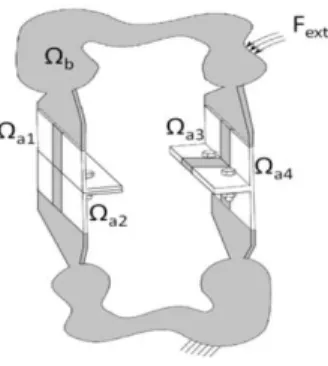
As proposed in [5] and illustrated in Figure 1, one distinguishes a big linear substructure and non-linear areas with significant details around interfaces. Use of reduction method [6] is proposed to allow the generation of a small size model for the linear part to perfectly match the system dynamics for a reference linear system. This first reduction makes computation of models with detailed non-linear parts accessible although costly. One is thus interested in introducing meta-models of the behavior in the non-linear part for faster computations and easier comparison with experiments.
* Corresponding author. Tel.: +33-0144246215.
-2- .
Figure 1: Linear structure with repeated non-linear joints
Following the rationale of [5,7], the first step is to determine a basis of the main joint deformations and associated principal loads. Demonstrating the range of validity of such meta-models will validate the identification of their properties through the use of experiments [7-9] or numerical simulations with the detailed non-linear model. A critical aspect of the work done here is to address the case of joints of a single geometry that are repeated multiple times, since this is typical of aeronautic construction and experiments on full structures are not acceptable for meta-model identification.
To detail possible variants to the proposed meta-model building procedure, the simpler case of a viscoelastic damping treatment as proposed in [1] is considered. In this case, accounting for the effects of variable stiffness is the target of a meta-model. Strategies for defining principal joint deformation and loads are first proposed. The possibility to truncate either joint deformations or loads is introduced. The need to enrich the base using the multi-model reduction approach [11] is also presented.
The proposed approaches are then tested on assemblies using bolted bracket joints, typical of aeronautic construction, connecting two boxes representing fuselage segments. A single meta-model is used for the various bolts and shown to allow proper representation of joint influence for variable joint properties, since studying these variations is the main step of damping design studies. Illustration of both efficient and inaccurate cases gives a better understanding of the meta-model validity.
2. Reduction on meta-models of multi-jointed structures 2.1. Reduced system formulations
A mechanical assembly fitted with identical bolted joints subjected to dynamic loads is considered here. The equation of motion defined in frequency domain of the system can be written under the finite element formulation as follows
+ × ( ) × + ( ( ), ) × = ( ) × , (1)
with the mass, the elastic stiffness matrix and the model degree of freedom. is the external forces vector. In the present work denotes the forces associated with a viscoelastic layer present in the joint whose properties can change with frequency and temperature. It is written as function of the viscoelastic stiffness matrix K depending on parameter as following
Chaima HAMMAMI/ Vibrations, Shocks and Noise 2014
-3-
( ( ), ) × = K ( ) × ( ) × (2)
It is clearly expected that in the future this work can be extended to the case of contact and friction forces where the load will depend of position, velocities and possibly internal states describing slip.
The model is first subdivided into two parts: a nonlinear part Ω including bolted joints (Ω = Ω | ! :#) and a linear part Ω$ including all the rest of the structure (Figure 1).
One is interested here to introduce a meta-model able to describe the nonlinear behavior of several joints. The objective of this meta-model is to allow prediction of joint behavior in terms of dominant effects whose characterization can help improve design.
Starting with the idea of principal deformations, one suggests to build a vector subspace % of dimension & characterizing the possible joint deformation. This leads to a change of model DOF characterized by
= ( ) )× ⋮ )# )× + +× , = -% )× . 0 0 0 0 ⋱ 0 0 0 0 % )× . 0 0 0 0 T+ +×. 2 3 4 5 4 6 )7 .× ⋮ )#7 .× +7.× 84 9 4 : = ;7 × 7 × , (3)
where, 7 is the generalized degrees of freedom vector which is reduced from & = × & + &$ to &< = × & +
.
Mode reduction occurs if & ≪ & and/or ≪ &$. The linear part Ω$ can be reduced by a T+ matrix that can be defined by several reduction methods : Craig-Bampton as proposed in [5], or the more efficient Component Mode Tuning [6]. The later will be used here but this choice is not the focus of this work. The reduced order formulation of the model defined by equation (1) is thus given by:> ;7 ;7 + ;7 ;7 ? 7 + ;7 = ;7 (4)
One defines a meta-model to be the description of forces associated with a state description of the joint )@7 thus allowing the constructions of equations of motion. The assumption that the meta-model does not depend on states in the linear part, implies that mass and stiffness contributions of the linear part Z++( ) and coupling terms Z+) ( ) are not part of the meta-model as detailed in [5]. Only nonlinear part Z) ( ) is thus considered here.
In the present case of viscoelastic damping an exact joint model is thus given by
) = ) + ) + ) ( ) ) = Z) (s, p) ) (5)
with ) , ) and ) respectively the mass, elastic and viscoelastic matrices depending of parameter , associated to one nonlinear part Ω . One will talk about a meta-model, if this model is reduced kinematically by considering a subspace % of dimension & ≪ & and/or if simpler expressions of ) through scalar principal loads are derived. 2.2. Principal joint deformations %
As stated in [5], the ideal case would be to have the ability to define independent non-linear forces that only depend on a single state. In the viscoelastic case (2), this would correspond to finding a basis V such that the dynamic stiffness Z) (s, p) is diagonal. This corresponds to the classical modal decomposition, performed here on the non-linear area around a joint rather than on the whole structure. One notes, > ) D E? = ) + ) ( F) the stiffness
-4-
matrix associated to the initial state of reference in which one can diagonalize forces. ) ( F) is the stiffness matrix defined for an initial parameter F (section 3). In the case of nonlinear contact and friction, a jacobian matrix linearizing the system around a given state will be considered.
The subspace V of principal joint deformations is solution of the eigenvalue problem
G− ) I|JK + > ) D E?L M%NO = 0 (6)
and the associated modes are well known to verify two orthogonality conditions
% > ) D E? % = >⋱ I|JK ⋱? (7)
% ) % = P (8)
From equation (8), one can write:
% Q = %
) (9)
The degrees of freedom vector associated to the nonlinear part Ω is defined as following:
) = % ) 7 (10)
Combining equation (9) and (10), one can obtain the generalized degrees of freedom vector from the full DOF using
) 7 = % ) ) (11)
While % can be computed for all degrees of freedom in Ω , the multi-model reduction approach would consider solutions that are a linear combination of simply computed shapes. In the present case, global system modes can be computed for the nominal model. One can thus build a multi-model collection of vectors by combining the six rigid body motion of the joint ΦS |T@U@V with the trace of global modes Φ : . of the nominal system on each joint Ω |@! :W.
; = ΦS |T@U@V ΦS | … ΦS |YZ … ΦSW| … ΦSW|YZ (12)
One then solves % in the subspace generated by this collection of vectors, thus obtaining a subspace that can represent nominal system modes exactly. Slight round-off errors are found to occur so an approximation is made but this approach allows the generation of principal deformation shapes that are characteristic of specific global modes. Keeping rigid body modes is necessary to obtain a meta-model that allows rigid body motion, which seems a basic requirement for a reusable model.
The choice of the reference stiffness is a first key aspect of the proposed procedure and probably its main limitation as will be shown later. The choice of a restricted set of target vectors is the second step that can strongly influence results.
Chaima HAMMAMI/ Vibrations, Shocks and Noise 2014
-5- 2.3. Meta-model forces
The main goal is to characterize nonlinear forces at joints interfaces through the bolted joint meta-modeling and experimental identification. This section thus details the expression of joint forces. Using orthogonality conditions defined in (7) and (8), the meta-model defined in (5) can be transformed to generalized V coordinates leading to
[ = \ ⋱ ⋱ + >⋱ I|JK ⋱? + % ) ( ) − ) ( F) %] ) 7 (13)
If one considers ) ( ) = % ( ) ( ) − ) ( F))%, three joint load approximations are illustrated in this work
• FV (Full ) : reduction of % and resolution of model (13). The only approximation is in the use of a reduced V.
• VD (full ^ and Diagonalization ): reduction of % and resolution of model (13) assuming ) to be diagonal
• PL (Principal Loads) : approximation of ) by a singular value decomposition (SVD) giving principal loads as follows
) ( ) ≃ ∑b!b ab cb ab , (14)
with, ) ( ) = a Σ % where a and % are unitary matrices and Σ = ⋱ cb ⋱ is a diagonal matrix of singular values.
Model (4) can be written under matrix form as following:
\ ;7 ;7 + ;7 D E ;7 + 7 ( ) ] e )
7
+7f = ;7 , (15)
where 7 ( ) = ;7 ( ) − ( F) ;7 is the reduced nonlinear stiffness matrix of the whole structure. One notes N = M%NO ) ) the jth component of ) 7 with = 1: and h = 1: & , and [ N = M%NO > ) ?M%NO N, the assumption of coupling of principal forces at joints is thus written as following: [ N = M%NO > ) ?M%NO N+ iM%NO > ) ? %b b
bjN
(16)
The second term defines the contribution of other modes k on mode h. Until today, there is no work on the construction of meta-model with a significant modal coupling on elementary structures. A high level of coupling between modes can be a limitation for the construction of a meta-model faithfully representative of the behavior of the junction. The idea is to determine the level of coupling here to deal with. The model (15) can thus be written as following:
-6- \ ;7 ;7 + ;7 D E ;7 ] e ) 7 +7f + 3 44 4 5 44 4 6[
⋮
[N⋮
[# ⋮ [#N l 844 4 9 44 4 : = ;7 (17)When writing previous equation as function of the elastic matrix, one can write the system under the following form: > ;7 ;7 + ;7 ;7 ? e ) 7 +7f + 3 4 4 4 5 4 4 4 6mI|Jn − % ) % o + [ ⋮ pI|JK − %N ) %Nq N+ [N ⋮ mI|Jn − % )#% o # + [# ⋮ pI|JK − %N )#%Nq #N+ [#N l 84 4 4 9 4 4 4 : = ;7 (18) 3. Sample application
In this section, the validity of the reduction approach with meta-modeling the bolted joints is investigated. The aim of the construction of the meta-model method is to build a simplified model that can simulate all the answers for a set of configurations. Therefore, an example of application is studied here through a parametric study that makes responses variations.
3.1. Parametric study of reduced model
The parametric study carried out in this section, focuses on the variation of nonlinear stiffness at interfaces. The model (15) is here written as following:
\ ;7 ;7 + ;7 D E ;7 + (r − rF, s − sF ) ] e )
7
+7f = ;7 , r, s ∈ ℝ
v (19)
Where r and s are the study parameters defining nonlinear matrix coefficients. The nonlinear matrix is linearized and defined as: (r, s) = ;7 (r w + s x ) ;7 where, w and x are respectively the normal and the tangent stiffness matrix. One defines in this study a state of reference defined as follows
Chaima HAMMAMI/ Vibrations, Shocks and Noise 2014
-7- 3.2. Model with two bolted bracket joints
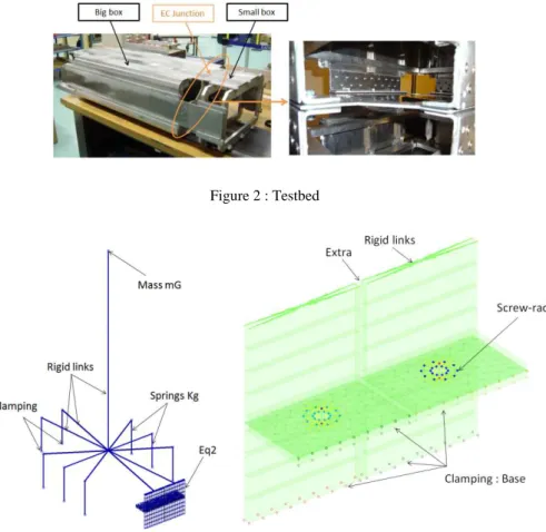
Mechanical assemblies representing several bolted joints are investigated in this work. In this context, on chooses as an example of application, a structure with two identical bolted bracket joints (Figure 3, Right) to begin with and representing a simple configuration to treat.
The investigated structure is originally composed of ten joints as it represents a testbed model of the FUI project MAIAS (Maîtrise des Amortissements Induits dans les ASsemblages) shown in Figure 2. This structure uses bolted bracket junctions, typical of aeronautic construction, connecting two boxes composed of frames, longerons and skin that are welded to limit dissipation outside the junction. The model, shown in Figure 3, and treated through this section represents an equivalent one to the testbed model. One then replaces eight joints by linear springs clamped in its bases to the ground and modeling the big box by a mass mG concentrated at gravity center coordinates. The two studied joints are clamped on the two free extremities of its inferior plates. To preserve contact area under the bolts head/nut, one defines a perfect contact between plates at this area (called ‘screw-rad at Figure 3) as illustrated in [1]. All components are linked with rigid links.
Figure 2 : Testbed
-8-
The two first modes are bending ones along two perpendicular directions defining respectively the big side and the small side of the model. The thirst mode is the torsional one. And the fourth one is the second bending mode in the big side direction. These are the global modes representing the main strains of the model studied in next section. 3.3. Enrichment of the subspace %
Based on the multi-model reduction method [11], one proposes here to enrich the subspace % with linear local models defining the variation of the normal and tangent stiffness matrix. This enrichment describes transitions between different configurations of joints interfaces behavior. One considers Φi = >Φ(r, s)S@| :YZ?, the subspace ; is now defined as follows:
; = ΦS |T@U@V Φ1(0,0) Φ1(0,1) Φ1(1,1) Φ2(0,0) Φ2(0,1) Φ2(1,1) (21)
3.4. Reduction validity: joint mode basis
In order to verify the validity of the meta-modeling approach, one is interested in this section in comparing full model response and the reduced model one investigated in this paper. However, in this work, the full response is replaced by the response of the model reduced with the multi-model method (MM) that has shown its efficiency compared to the full model.
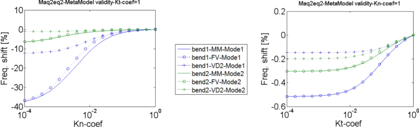
Figure 4 shows the evolution of the percentage of the frequency shift when varying normal and tangent stiffness at interfaces associated to the multi-model reduction and the reduction with meta-model approach in its two versions. The first version (FV) is when considering coupling of principal forces at joints. The second version (VD) is when decoupling modes with nonlinear matrices diagonalization. The first observation is that the structure presents a low degree of ability to dissipate for the two first mode of bending (bend 1 and bend 2). This conclusion is based on the low variation of frequency with the high variation of tangent stiffness. This is explained by the fact that these bending modes promote brackets opening. The second observation concerns the validity of the meta-model. The responses of the multi-model reduction method and the FV model are very close. With the VD model, responses predict a much smaller frequency shift and the model is thus clearly wrong. The next idea is thus to consider dominant forces going into joints and approximate reduced normal and tangent stiffness matrix based on important solicitations (PL).
The strategy of choosing the dominant solicitations needs investigation. When defining the first two bending modes to build the subspace V, one finds that four governing components of the reduced normal stiffness matrix are selected: two for each mode. The first bending mode promotes bracket opening which generates tension and torsional solicitations hence the two components. The second bending mode concerns also brackets opening but in other direction. However joints boundaries don’t work similarly. Two components are thus necessary to describe the load. In Figure 5, one compares this approach with the multi-model reduction and results are very close. However, when taking only the first two dominant loads (Figure 6), the results become different.
Chaima HAMMAMI/ Vibrations, Shocks and Noise 2014
-9-
Figure 4 : Comparison between multi-model reduction and reduction with FV meta-model
Figure 5 : Comparison between multi-model reduction and reduction with meta-model with 4 principal loads
Figure 6 : Comparison between multi-model reduction and reduction with PL meta-model with 2 principal loads
-10-
This work introduced a strategy for building a meta-model that can reproduce the dynamic behavior of bolted joints through principal loads. Application of this meta-model on multi-bolted joint models was investigated. Viscoelastic damping treatment was considered through effects of variable stiffness at joints interfaces and the ability to predict frequencies for varying normal and tangent stiffness was used for model validation. Three strategies for defining principal joints deformations and loads were illustrated. The base approach of principal joint deformations requires a large subspace and does not allow for a diagonal approximation of the effect of normal and tangent stiffness. Using an SVD to generate dominant loads to characterizing the joint gave promising results although truncation issues are still open. Future work will also focus on extensions to more realistic structures with cylindrical geometries and larger numbers of joints.
References
[1] C. Hammami, E. Balmes, et G. Guskov, « Conception et validation d’une liaison boulonnée dissipative », présenté à CSMA, 2013, vol. Giens, France.
[2] R. Wang, A. Crcombe, G. Richardson, et C. Underwood, « Modelling of damping in small satellite structures incorportaing bolted joints », présenté à Small Satellite conference, 2005.
[3] L. Gaul, S. Hurlebaus, J. Wirnitzer, et H. Albrecht, « Enhanced damping of lightweight structures by semi-active joints », Acta Mech., vol. 195, no 1‑4, p. 249‑261, 2008.
[4] L. Gaul et J. Lenz, « Nonlinear dynamics of structures assembled by bolted joints », Acta Mech., vol. 125, no 1‑4, p. 169‑181, 1997.
[5] H. Festjens, G. Chevallier, et J. Dion, « Nonlinear Model Order Reduction of Jointed Structures for Dynamic Analysis », Accept. JSV, no Journal Article, 2013.
[6] G. Vermot Des Roches, J. Bianchi, E. Balmes, R. Lemaire, et T. Pasquet, « Using component modes in a system design process », 2010, vol. Proceedings IMAC.
[7] D. J. Segalman, « Model Reduction of Systems With Localized Nonlinearities », vol. 2, 2007.
[8] D. J. Segalman, « A Four-Parameter Iwan Model for Lap-Type Joints », SandiaReport SAND2002-3828, 2002.
[9] M. Iranzad et H. Ahmadian, « Identification of nonlinear bolted lap joint models », Comput. Struct., vol. 96‑ 97, no Journal Article, p. 1‑8, 2012.
[10] L. Heller, E. Foltête, et J. Piranda, « Experimental identification of nonlinear dynamic properties of built-up structures », JSV, no 327, p. 183‑196, 2009.
[11] E. Balmes, « Parametric families of reduced finite element models. Theory and applications », Mech. Syst. Signal Process., vol. 10, no 4, p. 381‑394, 1996.