HAL Id: hal-02124841
https://hal.archives-ouvertes.fr/hal-02124841
Submitted on 9 May 2019
HAL is a multi-disciplinary open access
archive for the deposit and dissemination of
sci-entific research documents, whether they are
pub-L’archive ouverte pluridisciplinaire HAL, est
destinée au dépôt et à la diffusion de documents
scientifiques de niveau recherche, publiés ou non,
Effects of vibrating and deformed trailing edge of a
morphing supercritical airfoil in transonic regime by
numerical simulation at high Reynolds number
J.-B. Tô, Nikolaos Simiriotis, Abderahmane Marouf, Ioannis Asproulias, D.M.
Zilli, Yannick Hoarau, J.C.R. Hunt, Marianna Braza, Damien Szubert
To cite this version:
J.-B. Tô, Nikolaos Simiriotis, Abderahmane Marouf, Ioannis Asproulias, D.M. Zilli, et al.. Effects
of vibrating and deformed trailing edge of a morphing supercritical airfoil in transonic regime by
numerical simulation at high Reynolds number. Journal of Fluids and Structures, Elsevier, In press,
�10.1016/j.jfluidstructs.2019.02.011�. �hal-02124841�
Effects of vibrating and deformed trailing edge of a
morphing supercritical airfoil in transonic regime by
numerical simulation at high Reynolds number
J.-B. Tˆoa,2,∗, N. Simiriotisa,2, A. Maroufa,b,2, D. Szuberta,3, I. Asprouliasa,3, D. M. Zillia,1, Y. Hoaraub,4, J.C.R. Huntc,a,6, M. Brazaa,5,∗
aInstitut de M´ecanique des Fluides de Toulouse (IMFT), UMR 5502 CNRS-INPT-UT3,
All´ee du prof. Camille Soula, 31400 Toulouse, France
bICUBE, Unit´e Mixte C.N.R.S.-Universit´e de Strasbourg 7357, France cUniversity College London, United Kingdom
Abstract
This article examines the aerodynamic performance increase of an Airbus A320 aerofoil thanks to morphing of the near-trailing-edge region in transonic regime corresponding to cruise conditions. The study has been carried out by numerical simulation at Reynolds number Re = 2.06 × 10⁶and Mach number of 0.78, by using the NSMB code (Navier-Stokes MultiBlock) including adapted turbulence modelling approaches sensitised in capturing coherent structures development. It has been shown that transonic buffet occurs at angle of incidence 1.8° and in a more pronounced way at angle of 5°. The interactions among the shock-boundary layer area, the shear layers vortices and those of the near wake have been analysed by spectral analysis and streakline dynamics. Strong feedback effects have been shown from the near trailing-edge region towards the SWBLI
∗Principal corresponding author
Email addresses: jean-baptiste.to@imft.fr(J.-B. Tˆo), nikolaos.simiriotis@imft.fr (N. Simiriotis), abderahmane.marouf@imft.fr (A. Marouf), damien.szubert@imft.fr (D. Szubert), ioannis.asproulias@imft.fr (I. Asproulias), mitchelzilli@gmail.com (D. M. Zilli), hoarau@unistra.fr (Y. Hoarau), julian.hunt@ucl.ac.uk (J.C.R. Hunt),
marianna.braza@imft.fr(M. Braza)
1Graduate student 2PhD fellow
3Postdoctoral research fellow 4Professor
5Director of Research CNRS 6Professor Em.
(Shock Wave Boundary Layer Interaction) up to the upstream of the shock area. By taking benefit from these feedback effects, it has been obtained that morphing applied as a slight upwards deflection of the near-trailing-edge re-gion by 2° is able to practically attenuate the buffet instability and to increase lift-to-drag ratio by 10.4 percent. The trailing-edge’s area vibration at low amplitudes simulating the motion of piezo-patches of MFC type (Macro-Fiber Composites) applied experimentally in the context of the H2020 European re-search project www.smartwing.org/SMS/EU) has shown a lock-in effect of the buffet’s frequency. Therefore, a conditioning of the shock’s motion by means of these actuations can be reached, although a relative increase of the rms of the aerodynamic forces is produced in this case. The study of a combined upwards slight deflection and of trailing-edge area vibrations allowed obtaining decrease of drag and increase of lift-to-drag ratio with simultaneous decrease of rms. These effects have been studied for a wide frequency range from 200 to 500 Hz. Keywords: Morphing, Transonic buffet, Turbulence, Organized Eddy
Simulation OES, Von K´arm´an vortices, Shear layer
1. Introduction
A considerable number of experimental and numerical studies have been devoted to the investigation of the transonic interaction around a wing and particularly on buffet appearance, i.e the unsteady quasi-periodic shock’s motion over a wing, occurring in a specific Mach number range of (0.7 - 0.8) ([26]). This range corresponds to cruise conditions for which it is crucial to analyse the buffet dynamics in order to attenuate or suppress it, because it could create critical conditions for dip-flutter instability amplification with negative damping. The transonic buffet is a result of a fluid’s instability, due to a strong interaction among the shock, the boundary layer and the separated shear layers as well as the coherent vortices formed downstream of the trailing edge, whose dynamics influence each other in a closed loop. Pioneering experimental studies driven by Seegmiller et al. ([30]), McDevitt et al. ([26]), Levy Jr. et al. ([24]),
Marvin et al. ([25]) and more recently by Jacquin et al. ([21] and [22]) who investigated the SWBLI associated with the buffet dynamics and its effects on the wall pressure and the aerodynamic forces including PIV measurements. Collected experimental studies of the transonic buffet can be also found ([13]) in the context of the European research programme UFAST (Unsteady Effects in Shock Wave Induced Separation) and of the European research programme TFAST (Transition Location Effect on Shock Wave Boundary Layer Interaction) http://tfast.eu([12]).
In the last twenty five years, in parallel with experimental investigations, nu-merical studies examined the transonic interaction and the buffet phenomenon. Starting from the low Reynolds number range, the successive stages of insta-bilities amplification as Mach number increases had been studied through DNS and 2D numerical simulation by Bouhadji et al. ([3]). It was shown that first, a von K´arm´an instability mode is amplified in the wake and makes undulation of the two separated shear layers over a NACA0012 airfoil at Reynolds number of 10, 000. As Mach number increases from 0.5 to 0.6, a progressive formation of a slightly supersonic region upstream of the shock is formed and remains steady, while the von K´arm´an amplitude progressively increases. At Mach number of 0.7, a much lower-frequency mode appears in the forces fluctuations, that en-velopes a considerable number of periods of the von K´arm´an mode, while the upstream of the shock supersonic area starts oscillating according to this low frequency and gives birth to the buffet mode. These lower Reynolds number studies allowed precisely the follow-up of the above successive stages and made evidence of the history in the appearance of the different instability modes, a fact that is difficult to observe experimentally, because the amplification of these modes in the high Reynolds number range occurs quite fast.
As Mach number increases in the range (0.7-0.8), the buffet amplitudes in-crease and continue enveloping the von K´arm´an mode periods, while the av-eraged shock position progressively moves downstream. As Mach number in-creases up to 0.85, only the von K´arm´an mode persists up to Mach numbers 0.9 in the forces fluctuations, while the wall pressure is practically steady. This
is due to the shock wave occurrence in most downstream positions because of the progressive increase of the hyperbolic character of the flow with the Mach number increase. At Mach numbers in the range (0.9 - 0.95) the shock wave has moved in the wake and the forces are steady.
Considering 3D studies, Bourdet et al. ([4]) studied the buffet instability
am-plification by DNS and by means of the Landau global oscillator model around a NACA0012 airfoil. The DNS study illustrated the secondary instability ampli-fication and the formation of spanwise undulated vortex structures in the near wake, governed by predominent large-scale wave lengths. This pattern persists in the high Reynolds number range concerning the three-dimensional character of the coherent structures past the trailing edge, as shown by Delayed Detached Eddy Simulation in Grossi et al. ([16]) around a supercritical wing, the OAT15A a Mach numbers corresonding to the buffet ocurrence and Reynolds numbers of order 3 Million, studied in the context of the European research programme ATAAC7. In these studies, the shock wave structure and the buffet dynamics were found not considerably affected by the three-dimensionnality. For these reasons, as mentioned below, a two-dimensional approach can be used in order to ensure a rich parametric study concerning the morphing effects. Moreover, the Zonal Detached Eddy Simulations, ZDES by Deck et al. ([11]) presents a quite complete analysis of the transonic interaction around the OAT15A and a promising turbulence modelling approach.
Moreover, 2D URANS studies at high Reynolds numbers ([9]) have also provided a detailed physical analysis of the buffet around the same configuration. More recently, Szubert et al. [32] studied the transonic interaction among the buffet, the shear layer vortices and the von K´arm´an vortices by 2D numerical simulation using the Organised Eddy Simulation, OES ([8] and [5]). Through this method, able to capture the instabilities amplification and the coherent structure dynamics in 2D and 3D, the transonic interaction was studied as well as its impact on the pressure and forces fluctuations, by means of wavelets and
Proper Orthogonal Decomposition (POD). The role of the higher-order modes in producing a shear sheltering effect in the separated shear layers past the SWBLI was analysed and used to create a stochastic forcing by re-injection of turbulence in these layers and in the shock’s shearing region, as source terms in the turbulence transport equations, in the so-called IOES (Improved OES) approach. This forcing acts as an eddy-blocking effect as described in ([20]) resulting in a considerable thinning of the shear layers and of the wake’s width. This effect, besides a significant improvement of the pressure coefficient and the forces evaluation, is used in the present study in order to enhance the benefits from the morphing as described in the results discussion.
Moreover, the transition location effects on the buffet have been studied and optimised in the same high Reynolds number range for the supercritical wing V2C design by Dassault Aviation in the context of the TFAST European project. Szubert et al. ([31]) studied by DDES/OES the transonic buffet and carried out an optimisation of the transition location. The study by Bonne ([2]) proposed quite successful physical models of the laminar SWBLI that allowed analysis of the multi-modal coupling in the high Reynolds number range, offering physi-cal mechanisms comprehension of high interest for the industrial applications, including buffet study in swept wings by numerical simulation.
The objective of the present article is to study the effects of morphing on the flow dynamics regarding an unconfined 2D configuration to help the design the A320 morphing prototype in the context of the H2020 European research project SMS8. This study will serve to implement the best type of actuations near the trailing edge of the experimental prototype, in order to obtain optimal increase of the aerodynamic performance. To this end, the actuations studied in the present paper by means of numerical simulation are in accordance with the hardware actuations studied in a number of experimental works of the present research group in the context of the SMS research platform, supported by the French Foundation “Sciences et Technologies pour l’AÃľronautique et l’Espace”
- (STAE), http://www.fondation-stae.net/ and in other recent studies as follows.
It has been shown ([28] and [29]) that vortex breakdown occurs by trail-ing edge vibrations ustrail-ing PUSH-PUSH piezoactuators in the trailtrail-ing-edge re-gion of a NACA0012 wing, with asignificant lift improvement, drag and noise sources decrease, in the context of the STAE Research projects research project EMMAV - Electroactive Morphing for Micro-Airvehicles using Shape Memory Alloys (SMA) ([10]) and DYNAMORPH: “Dynamic Regime Electroactive Mor-phing”, by means of a combined action of SMA and piezoactuators ([28]). Fur-thermore, the European research programme SARISTU9 had considered mor-phing trailing edge devices through SMA and MEMS. The European programme SADE10developed morphing devices for the leading edge and the wings by us-ing flexible matrix composites (FMC). In particular, the MFC piezoactuators provided good performances in subsonic flow conditions ([28] and [23]). The actuation concept associating different degrees of deformation and vibration at multiple time scales is called hybrid electro-active morphing in these studies by the multidisciplinary research group IMFT-LAPLACE. It was demonstrated that the flow dynamics are significantly affected by the trailing edge actuation. An important reduction of the wake’s width and spectral energy associated to drag and aerodynamic noise respectively was quantified by means of Particle Image Velocimetry (PIV) measurements. In the context of these studies, the aim of the hybrid morphing concept is to use the turbulence itself, in order to manipulate part of the ”harmful” eddies and to enhance the beneficial ones thanks to the “eddy blocking effect” ([20]) previously mentioned. The objective is to increase the aerodynamic performances and simultaneously decrease the noise sources generated from predominant instability modes. Hence at a given controlled camber, the vibrating trailing edge adds kinetic energy in the wake that fosters the suppression of coherent turbulent structures. This kind of
ac-9http://www.saristu.eu
tuation is precisely studied numerically in the present article, together with a slight upwards deflection. It is worthwhile mentioning that in transonic speeds, only slight deformations of the rear region are recommended, whereas in low subsonic speeds, large deformations are needed. Therefore the present article will examine the effects of slightly deformed and vibrating trailing-edge region in a wide frequency range, first as a stand-alone actuation and secondly com-bined with a slight static deflection of the rear part, which was proven beneficial in recent studies of us ([35]).
There do not exist, to our knowledge, studies concerning morphing in tran-sonic regimes where the target is to increase lift-to-drag ratio and to decrease drag and acoustic generation. The numerical study by Barbut et al. ([1]) by means of DDES (Delayed Detached Eddy Simulation) investigated the dynam-ics around a NACA0012 wing with an oscillating trailing edge in the transonic regime. An experimental and numerical study around this wing can be found in a work by Braza et al. ([6]).
Therefore, the objectives of this paper are to examine the effects of morph-ing of the rear part of the wmorph-ing by suitable deformations and vibrations able to manipulate the surrounding turbulence and vortex dynamics and able to be realised in experimental environment and in real flight. This paper is thus artic-ulated as follows: In the first section, the numerical parameters and turbulence modelling are introduced. Secondly, the results are presented investigating the effects of morphing on the aerodynamic performance of the wing by different trailing-edge vibrations, by a slight deformation upwards and by combining both actuations. The results are discussed regarding optimal behaviours in respect of aerodynamic performance and finally the conclusions are drawn in the last part of the article.
2. Flow regime, numerical parameters and Turbulence Modelling
The configuration investigated is a supercritical AIRBUS A320 wing the rear part of which is deformable and vibrating according to specific frequencies
dic-tated by the electroactive morphing studies carried out in the SMS European project for the cruise speed design. The free-stream Mach number is 0.78 and the chord-based Reynolds number is 2.06 × 10⁶. The chord length is 0.15 m with respect to the experimental mock-up designed for the wind tunnel of the IMP-PAN Academy of Science in Gdansk ([15]), Poland within the partnership of this European project. Two angles of incidence are investigated: α = 1.8° and α = 5°. The first angle is a standard cruise speed angle. The second can also occur in cruise depending on the wind direction but it lasts shorter than the nominal cruise angle of 1.8°. Furthermore, this angle of 5° has been chosen because it enhances boundary layer separation and the transverse veloc-ity gradients across the separated shear layers. Therefore, this angle allows a more pronounced interaction between the separated region and the shock, thus offering a comprehensive analysis of the mechanisms.
The morphing strategies investigated in the present study have the objective to accompany the prototype’s design. The trailing edge region can be slightly deformed and vibrate thanks to piezoactuators at frequencies of a few hundred Hz up to an order of thousand Hz. This kind of piezoactuators have been studied for subsonic speed regimes by [23] and can be adapted in the present transonic speeds according to the present numerical simulations.
a b
Figure 1: (a) Computational grid over the A320 airfoil and (b) zoom around the wall area.
This 2D transonic flow simulation around an A320 airfoil is realised by using the Navier-Stokes Multi Block (NSMB) code ([19]), solving the complete system
of the Navier-Stokes equations with advanced turbulence models in finite-volume formulation. Based on previous detailed studies of our research group by [16] and [32], spatial fluxes are discretised using a 3rd order Roe scheme with MUSCL Van Leer limiter, while a 2nd order backward dual-time stepping scheme is chosen for time integration.
A two-dimensional multi-block structured grid has been used for the com-putations. Two different grids have been examined and an exhaustive study of the grid influence, and time step has been carried out. Initially, a coarser grid of 160000 computational cells had been compared with a finer grid containing 190000-elements, both of C-H topology. This grid has been finally used for all the computations. The computational domain and geometry are deformed by using the Arbitrary Lagrangian-Eulerian (ALE) method to represent a dynamic deformation and motion of the trailing edge during morphing.
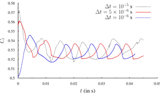
For this fine grid, a detailed sensitivity study in respect of the time step has been carried out. The results concerning the lift coefficient are presented in fig. 2. It is shown that ∆t = 5 × 10⁻⁶s and ∆t = 10−6s give practically similar results, therefore the value of ∆t = 5 × 10⁻⁶s has been finally chosen in order to obtain accurate results with a reasonable CPU time.
0.5 0.51 0.52 0.53 0.54 0.55 0.56 0.57 0.58 0 0.01 0.02 0.03 0.04 0.05 Cl t (in s) ∆t = 10−5s ∆t = 5 × 10⁻⁶s ∆t = 10−6s
Figure 2: Time series of the Cl coefficient for different time steps. For ∆t ≤ 5 × 10⁻⁶,
convergence is reached.
Concerning the turbulence modelling, the Organised Eddy Simulation (OES) approach ([8], [5] and [32]) is used in order to simulate the present flows at
high Reynolds numbers governed by the dynamics of coherent structures and chaotic turbulence. Based on our previous studies, this approach ensures a correct representation of the complex interaction between coherent structures and chaotic turbulence and it is efficient even in two-dimensional computations. Furthermore, it allows predicting the dynamics of the shock-vortex interaction.
3. Results
First, the static configuration will be examined as well as the dynamics of buffet. Secondly, vibration effects of the rear part will be investigated with re-spect to the buffet dynamics at angles of incidence α = 1.8° and α = 5°. Finally, two morphing effects are discussed concerning the aerodynamic performances. 3.1. Analysis of the buffet dynamics in relation with the shear layer and wake
structure
The buffet phenomenon displaying a periodic shock motion and the associ-ated growth and thinning of the separassoci-ated area is illustrassoci-ated in figures 3a to 3f. These figures correspond to α = 5°. This angle of incidence enhances the shearing mechanisms and the coherent structure appearance.
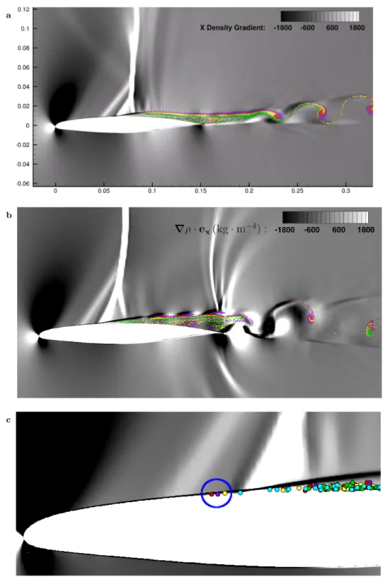
Figure 4 shows the longitudinal density gradient isocontours together with streaklines generated from x/c ≈ 0.6 . The particles shed in the flow highlight the boundary layer separation, the shear layer and wake instabilities leading to Von K´arm´an vortices. Following the shock motion along the suction side, the boundary layer becomes thinnest as the shock is in the most downstream posi-tion (fig. 4a) while the separated region becomes thickest as the shock reaches its most upstream position (fig. 4b). This is accompanied by the appearance of Kelvin-Helmholtz vortices along the separated shear layer. A video with the overall motion of the flow dynamics can be found in http://smartwing. org/SMS/EU/streaklines_video_transonic_interaction_a320/. Fig. 4c is a zoom around the lambda shock pattern and the separated region. It dis-plays the motion of the streakline particles below this pattern up to positions
a b
c d
e f
Figure 3: One buffet period represented by 6 snapshots. From left to right, top to bottom, the pictures correspond to times t∗=n0;1
5; 2 5; 3 5; 4 5; 1 o
where t∗is a non-dimensional time
defined by t∗= t−to
Tb , Tbbeing the buffet period and t0the arbitrary moment chosen as the
beginning of one buffet period. Here, t0corresponds to a moment when the shock is weakest,
i.e. when it reaches its most downstream position (see [33]).
upstream of the shock foot. These facts indicate the strong feedback effect between the separated region and the shock and a momentum transfer up-stream creating a local thickening of the boundary layer and an acceleration area above it. This is associated with the first oblique supersonic formation
indicated by the arrow. This pattern is actually observed practically in a systematic way in a number of Schlieren experimental visualisations ([14] and https://history.nasa.gov/SP-440/ch7-2.htm). The overall separated area together with the upstream boundary layer thickness form an “effective obsta-cle” thicker than the nominal airfoil, surrounded by an irrotational flow. It would be possible to evaluate the shock positions by an Euler computation around the shape of this effective obstacle.
The interaction between two (or among three or more) predominant incom-mensurate frequencies governing a dynamic system issued from the development of the turbulent motion around the body is known to produce new frequencies towards a filling-up of the energy spectrum by a multitude of frequencies in-cluding distinct peaks due to the coherent structures and continuous frequency ranges due to the chaotic turbulence. This was shown in experimental studies past a cylinder in high Reynolds number by Braza et al. [8] (cf. spectrum in p. 761, fig. 2b) among other studies. A similar behaviour was obtained in the experimental study by Jodin et al. [23] (p. 285, fig. 28). Hence, the turbulent spectrum displays distinct peaks corresponding to these predominant frequen-cies and new frequenfrequen-cies which are combination of the previous ones, as well as interspersed continuous frequency regions associated with chaotic turbulence motion. The interaction among all these patterns leads to a complex turbulence motion in which persists the trace of the coherent motion related to each main predominant frequency. The generation of this chaos is known to be non-linear, despite the fact that the new generated frequencies are linear expressions of the
initial predominant ones, of the kind mf1± nf2. This scenario had been
math-ematically analysed by Ruelle, Takens & Newhouse [27], reported for instance in Guzman et al. [17] (p. 2001), mentioned in previous studies by Braza et al. [7] (p. 1469), among others. The non-linearity can be also understood by the fact that the amplitudes of the predominant frequencies are not «doubled» if the upstream velocity is doubled. This fact is known by a number of studies, as for example in Hoarau et al. [18] (p.66, fig. 1a), where in the spectrum the amplitudes of the predominant peaks do not increase proportionally to an
increase in the Reynolds number. In the present case, predominant frequencies
shown in the spectrum of figure 10 are: the buffet mode, named fB, the
fre-quency corresponding to the von K´arm´an mode, fV K which corresponds to the
bump indicated in this figure. The bump formation around the von K´arm´an mode is due in the present case to a smearing of the alternating eddies in re-spect of amplitude and phase irregularities due to the high-Reynolds number chaotic motion. A representative frequency of this mode can be detected as a peak having a maximum amplitude within the bump, as was analysed in similar transonic regimes by Szubert et al. [32], (p. 285). In the present study, it is
indicated in figure 6 as fV K, a representative peak in the bump region
corre-sponding to the alternating vortex shedding, identified by tracking the vortices shed in the wake. These facts are associated to feedback effects as described in the following.
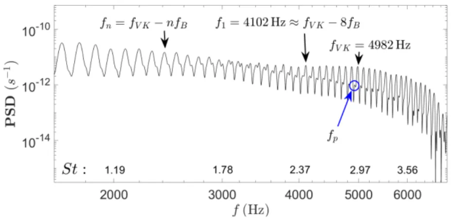
In the bump region, in addition to the main oscillations, there appears a
smaller pattern characterized by a frequency named «fp» of lower amplitude.
The high amplitude of the main frequencies in the bump progressively diminishes towards lower frequency values (towards the left of the figure). Around the frequency range of 3500 towards 3000 Hz, an inversion in the magnitude of
this amplitude and of the fp peak occurs, because the amplitude of this mode
becomes higher and is progressively merged with the harmonics of the buffet frequency for lower frequency values (left hand side of the figure). Due to the
fact that the buffet frequency is in the low frequency range (fB ≈ 110 Hz),
this mechanism occurs towards upstream spatial positions in the vicinity of the shock, illustrating therefore a feedback mechanism among the near wake region and the SWBLI. Furthermore, this figure indicates the appearance of the
aforementioned interaction between fB and fV K, by considering for example
the peak at f1= fV K−8fB. It can be seen that any of the peaks at frequencies
lower than f1 are of the kind fV K − nfB with n integer. Therefore, these
elements illustrate the feedback mechanism between the near wake region and the shock motion upstream.
area and in the near wake significantly affect the SWBLI region and the shock buffet. We will show that morphing appropriately uses the feedback effects from the near-trailing edge and wake area towards the shock area. This study will show the possibility of buffet attenuation by manipulating the shear layer and coherent structure dynamics, with high benefits in the aerodynamic perfor-mance.
3.2. The effects of morphing
3.2.1. The effect of a vibrating trailing edge
Morphing in this study is achieved numerically using the ALE method to de-form the trailing edge (see fig.7) by either deflecting it upwards quasi-statically or making it vibrate at higher frequencies. This flexible high-frequency vibra-tion of the trailing edge, here denoted “flapping” can be performed at various frequencies and was experimentally realised by [23], where morphing at multiple time and length scales was done thanks to different classes of electric actuators, the so-called hybrid electroactive morphing ([29]).
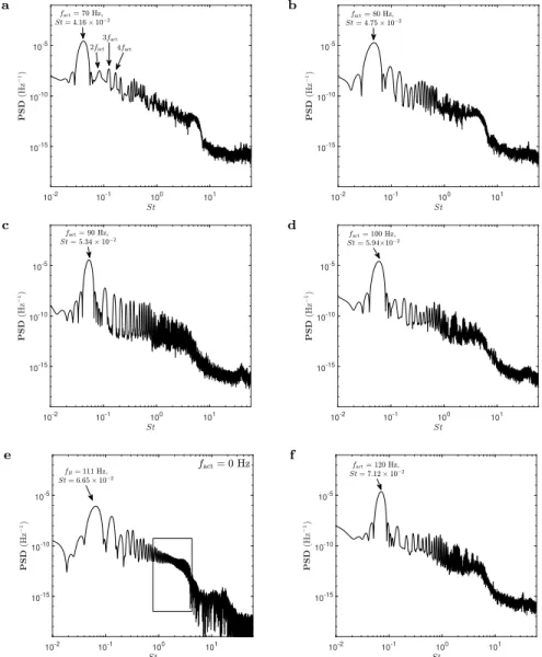
The effects of morphing on aerodynamic forces are firstly investigated for cases where the trailing edge is made to vibrate at various frequencies between 70 Hz and 500 Hz for an angle of incidence α = 1.8°, of the same order or magnitude as the natural frequency of the buffet instability, which has been found to be fB = 111 Hz, therefore a Strouhal number of St = 6.65 × 10⁻².
Flapping is thus performed at fact = 70; 80; 90; 100 and 120 Hz that are neighbouring the natural frequency of buffet fB = 111 Hz for a static wing at an angle of incidence α = 1.8°. Afterwards, the influence of higher frequency actuations in the range [200, 500] Hz have been investigated.
For all actuation frequency cases examined, it has been found the the buffet frequency locks on the flapping frequency, as shown in figures 5a, 5b, 5c, 5d and 5f by means of spectral analysis using a sliding windowing FFT (cf. [34]).
In fact, the upward movement of the trailing edge compresses the boundary layer, forcing it to move up while the downward movement in the second part of a flapping cycle induces a slight pressure decrease in the boundary layer over
the suction side of the wing. This leads the boundary layer to follow the exact same motion as the trailing edge, thus imposing the frequency of the buffet instability.
Additionally, the actuation was found to increase the amplitude of the force oscillations due to buffet as seen in figure 8 for instance. This arises from the increased aerodynamic loads due to the movement of the trailing edge, and the unsteady motion of the shock and boundary layer which has been locked on the actuation frequency.
This explains why the rms of the forces (cf. 8 and 9) increase.
Table 1 presents the relative changes of the average aerodynamic forces (lift, drag and lift to drag ratio). An increase of the lift coefficient can be noted in all cases. However this increase is more pronounced in the vicinity of 300 Hz and 500 Hz. The drag coefficient decreases in the range of 300 to 400 Hz. The lift to drag ratio increases as a function of the vibration frequency with a slight decrease around 400 Hz. Frequency of actuation (Hz) 200 300 400 500 hCli − hClistatic hClistatic ×100 +1.18% +1.31% +0.95% +1.43% hCdi − hCdistatic hCdistatic ×100 +1.31% +1.22% +0.88% +1.09% hCl/Cdi − hCl/Cdistatic hCl/Cdistatic ×100 -0.21% +0.09% +0.06% +0.33%
Table 1: Relative change (percentage) of lift, drag and lift-to-drag coefficients between the morphing case and the static case for various actuation frequencies.
3.2.2. Effects of an upward trailing edge deflection in static configuration and combined with a vibrating motion
A slight deflection upwards of the trailing edge is considered (order of 2°, cf. fig. 7). This deflection locally changes the incidence of the flow around the
trailing edge and reduces the adverse pressure gradient causing a consequent thinning of the separated region. Therefore, the interaction between the shear-ing region and the shock is weaker than in the static case and consequently buffet is attenuated.
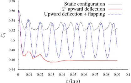
In figure 8, the lift coefficient is plotted versus time at α = 1.8°. In the static case, the periodic motion is due to the buffet phenomenon. In the configuration corresponding to the upward deflection without vibration, a reduction in the lift coefficient is obtained but the lift rms becomes almost zero. As shown in figure 9 and by table 3, the average drag coefficient value diminishes by 21.1% when a deflection of the trailing edge is applied. Finally, a combined deflection and vibration at 90 Hz shows a lower average lift decrease but higher lift rms values, cf. 4. For this case, the drag coefficient also shows a higher rms and a slightly higher mean value than the deflected case. The relative percentages are shown in tables 3, 4.
The lift to drag ratio is presented in table 2. While a good percentage increase corresponds to the combined case, an even higher benefit is obtained for the deflected case for the angle of incidence α = 1.8° corresponding to the cruise standard incidence.
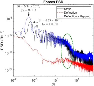
The morphing effects in the frequency domain are shown in fig. 10. The static case displays a bump in the low frequency range with a predominant frequency of 111 Hz. Harmonics of this fundamental frequency are also shown to extend towards Strouhal number ranges near 1, where a second frequency bump is formed. This corresponds to the Von K´arm´an instability mode and its interaction with the shear layer vortices past the trailing edge and in the near-wake.
The region between this bump and the buffet’s bump illustrates the non-linear interaction and feedback effects from the trailing edge and near-wake coherent structures to the SWBLI region and vice versa.
It is clear that morphing manages to reduce both the average values lift and drag, as well as to increase the mean lift to drag ratio. The drag reduction is
due to the diminution of the separated region’s size thanks to the adverse pres-sure gradient decrease near the trailing edge by means of morphing. The flap-ping motion actuated with quite small amplitudes (order of 0.2 mm) generates small scale vortices interacting with the separated shear layers delimiting the Turbulent/Non-Turbulent (TNT) interfaces, creating a shear sheltering through the eddy-blocking effect ([32] and [20]). This results in a shape drag reduction and consequently a reduction of the overall drag.
Incidence α= 1.8 α= 5
Type of actuation D D+F D D+F
hCl/Cdi − hCl/Cdistatic hCl/Cdistatic
×100 +10.4% +4.3% +2.5% +0.4%
Table 2: Relative change in terms of mean lift to drag ratio compared to the static case. Note that D means ”2° deflection” and ”D+F” is the superposition of an immobile upward deflection and a 90 Hz flapping motion.
Incidence α= 1.8
Type of actuation D D+F
hCdi − hCdistatic hCdistatic
×100 -21.1% -9.47%
Table 3: Relative change of mean drag compared to the static case.
Incidence α= 1.8
Type of actuation D D+F
hCli − hClistatic hClistatic
×100 -12.9% -5.37%
4. Conclusions
This paper enlightens the buffet dynamics strongly related with the shear layer and near-wake structure. The modification in the width of the separated region and of the coherent vortices near the trailing edge has been quantified and associated with the shock’s motion along the suction side. It has been shown through streaklines visualisation that the reverse flow passes through the lambda shock region towards a position upstream of the shock. This explained the formation of an oblique shock region upstream of the normal shock, visible in a considerable number of Schlieren experimental visualisations and less discussed up to now.
This article thus makes evidence of considerable feedback effects of the near trailing edge dynamics in relation to the SWBLI. The actuations investigated made use of these effects to produce a lock-in of the buffet’s frequency with the actuation frequency and furthermore to reduce the separated region and wake’s width. The slight upwards deflection has proven the most efficient in respect of lift to drag increase and drag reduction as well as a simultaneous rms reduction. These facts are crucial for the design because buffet onset leads to a high rise of drag and in extreme conditions can trigger dangerous dip-flutter modes.
5. Acknowledgements
The authors are grateful to the LAPLACE (Laboratoire Plasma et Conver-sion d’Energie), UMR CNRS-INPT-UT3 N° 5213, research group GREM3 on electrodynamics and to the National Supercomputing centers CALMIP, CINES and IDRIS for the Computer allocation, as well as the PRACE Supercomputing allocation N° 2017174208. This study has been realised under the H2020 Euro-pean Research programme N° 723402: SMS, “Smart Morphing and Sensing for aeronautical configurations”, http://smartwing.org/SMS/EU/.
References
[1] G. Barbut, M. Braza, Y. Hoarau, G. Barakos, A. S´evrain, and J. B. Vos. Pre-diction of transonic buffet around a wing with flap. Notes on Numerical Fluid Mechanics and Multidisciplinary Design, 111:191–204, 2010.
[2] N. Bonne. Stabilit´e de l’interaction onde de choc/couche limite laminaire. PhD thesis, Mar 2018.
[3] A. Bouhadji and M. Braza. Physical analysis of unsteady viscous flow phenomena around a wing by Direct Navier-Stokes Simulation. In Proceedings of the 4th ECCOMAS Computational Fluid Dynamics Conference. 1998.
[4] S. Bourdet, A. Bouhadji, M. Braza, and F. Thiele. Direct Numerical Simulation of the Three-Dimensional Transition to Turbulence in the Transonic Flow around a Wing. Flow, Turbulence and Combustion (formerly Applied Scientific Research), 71(1-4):203–220, 2003.
[5] R. Bourguet, M. Braza, G. Harran, and R. El Akoury. Anisotropic Organised Eddy Simulation for the prediction of non-equilibrium turbulent flows around bodies. Journal of Fluids and Structures, 24(8):1240–1251, 2008.
[6] M. Braza, G. Barbut, M. Miller, W. Kania, Y. Hoarau, G. Barakos, and A. S´evrain. NACA0012 with Aileron. Notes on Numerical Fluid Mechanics and Multidisciplinary Design, 114, 2011.
[7] M. Braza, P. Chassaing, and H. Ha Minh. Prediction of large-scale transition features in the wake of a circular cylinder. Physics of Fluids A: Fluid Dynamics, 2(8):1461–1471, Aug 1990.
[8] M. Braza, R. Perrin, and Y. Hoarau. Turbulence properties in the cylinder wake at high Reynolds numbers. Journal of Fluids and Structures, 22(6-7):757–771, 2006.
[9] V. Brunet. Computational Study of Buffet Phenomenon with Unsteady RANS Equations. In 21st AIAA Applied Aerodynamics Conference, Reston, Virigina, jun 2003. American Institute of Aeronautics and Astronautics.
[10] M. Chinaud, J.F. Rouchon, E. Duhayon, J. Scheller, S. Cazin, M. Marchal, and M. Braza. Trailing-edge dynamics and morphing of a deformable flat plate at high Reynolds number by time-resolved PIV. Journal of Fluids and Structures, 47:41–54, may 2014.
[11] S. Deck. Numerical simulation of transonic buffet over an airfoil. AIAA journal, 43(7):1556–1566, 2005.
[12] P. Doerffer, P. Flaszynski, C. Hirsch, J.-P. Dussauge, H. Babinsky, and G. N. Barakos. Sci. Eds., Transition Location Effect on Shock Wave Boundary Layer Interaction, volume (in print) of Notes on Numerical Fluid Mechanics and Mul-tidisciplinary Design. Springer, 2019.
[13] P. Doerffer, C. Hirsch, J.-P. Dussauge, H. Babinsky, and G. N. Barakos. Sci. Eds., Unsteady Effects of Shock Wave Induced Separation, volume 114 of Notes on Numerical Fluid Mechanics and Multidisciplinary Design. Springer, 2011. [14] W. J. Duncan, L. Ellis, and C. Scruton. First report on the general investigation
of tail buffeting. Aeronaut. Research. Com. R. & M., 1457, part I., 1932. [15] P. Flaszynski, P. Doerffer, R. Szwaba, M. Piotrowicz, and P. Kaczynski.
Laminar-turbulent transition tripped by step on transonic compressor profile. Journal of Thermal Science, 27(1):1–7, feb 2018.
[16] F. Grossi, M. Braza, and Y. Hoarau. Prediction of Transonic Buffet by Delayed Detached-Eddy Simulation. AIAA Journal, 52(10):2300–2312, 2014.
[17] A.M. Guzman and C.H. Amon. Transition to chaos in converging-diverging chan-nel flows: Ruelle-Takens-Newhouse scenario. Physics of Fluids, 6(6):1994–2002, Jun 1994.
[18] Y. Hoarau, M. Braza, Y. Ventikos, D. Faghani, and G. Tzabiras. Organized modes and the three-dimensional transition to turbulence in the incompressible flow around a NACA0012 wing. Journal of Fluid Mechanics, 496, dec 2003. [19] Y. Hoarau, D. Pena, J. B. Vos, D. Charbonnier, A. Gehri, M. Braza, T. Deloze,
and E. Laurendeau. Recent Developments of the Navier Stokes Multi Block (NSMB) CFD solver. In 54th AIAA Aerospace Sciences Meeting, AIAA SciTech Forum. American Institute of Aeronautics and Astronautics, jan 2016.
[20] J.C.R. Hunt, I. Eames, and J. Westerweel. Vortical Interactions with Interfacial Shear Layers. In Yukio Kaneda, editor, IUTAM Symposium on Computational Physics and New Perspectives in Turbulence, pages 331–338, Dordrecht, 2008. Springer Netherlands.
[21] L. Jacquin, P. Molton, S. Deck, B. Maury, and D. Soulevant. An Experimental Study of Shock Oscillation over a Transonic Supercritical Profile. In 35th AIAA Fluid Dynamics Conference and Exhibit, Reston, Virigina, jun 2005. American Institute of Aeronautics and Astronautics.
[22] L. Jacquin, P. Molton, S. Deck, B. Maury, and D. Soulevant. Experimental Study of Shock Oscillation over a Transonic Supercritical Profile. AIAA Journal, 47(9):1985–1994, 2009.
[23] G. Jodin, V. Motta, J. Scheller, E. Duhayon, C. D¨oll, J. F. Rouchon, and M. Braza. Dynamics of a hybrid morphing wing with active open loop vibrating trailing edge by time-resolved PIV and force measures. Journal of Fluids and Structures, 74:263–290, 2017.
[24] L.L. Levy Jr. Experimental and Computational Steady and Unsteady Transonic Flows about a Thick Airfoil. AIAA Journal, 16(6):564–572, jun 1978.
[25] J.G. Marvin, L.L. Levy Jr., and H.L. Seegmiller. Turbulence Modeling for Un-steady Transonic Flows. AIAA Journal, 18(5):489–496, may 1980.
[26] J.B. McDevitt, L.L. Levy Jr., and G.S. Deiwert. Transonic Flow about a Thick Circular-Arc Airfoil. AIAA Journal, 14(5):606–613, may 1976.
[27] S. Newhouse, D. Ruelle, and F. Takens. Communications in mathematical physics., volume 64. Springer-Verlag, 1978.
[28] J. Scheller. Electroactive morphing for the aerodynamic performance improvement of next generation airvehicles. PhD thesis, oct 2015.
[29] J. Scheller, M. Chinaud, J. F. Rouchon, E. Duhayon, S. Cazin, M. Marchal, and M. Braza. Trailing-edge dynamics of a morphing NACA0012 aileron at high Reynolds number by high-speed PIV. Journal of Fluids and Structures, 55:42–51, 2015.
[30] H. L. Seegmiller, J. G. Marvin, and L. L. Levy. Steady and unsteady transonic flow. AIAA Journal, 16(12):1262–1270, 1978.
[31] D. Szubert, I. Asproulias, F. Grossi, R. Duvigneau, Y. Hoarau, and M. Braza. Numerical study of the turbulent transonic interaction and transition location effect involving optimisation around a supercritical aerofoil. European Journal of Mechanics - B/Fluids, 55:380–393, Jan 2015.
[32] D. Szubert, F. Grossi, A. Jimenez Garcia, Y. Hoarau, J.C.R. Hunt, and M. Braza. Shock-vortex shear-layer interaction in the transonic flow around a supercritical airfoil at high Reynolds number in buffet conditions. Journal of Fluids and Struc-tures, 55:276–302, 2015.
[33] H. Tijdeman. Investigation of the transonic flow around oscillating airfoils. Na-tional Aerospace Lab. Amsterdam, Netherlands, TR-77-090U, 1977.
[34] P. Welch. The use of fast Fourier transform for the estimation of power spectra: A method based on time averaging over short, modified periodograms. IEEE Transactions on Audio and Electroacoustics, 15(2):70–73, Jun 1967.
[35] D. M. Zilli. Numerical Simulation and modeling of morphing deformation on a supercritical airfoil wing at high Reynolds number - Eng. Diploma thesis, EN-SEEIHT, Institut National Polytechnique Toulouse, Sep 2015.
a
b
c
Figure 4: Visualisation of the transonic interaction dynamics for α = 5° by means of longitu-dinal density gradient isocontours and streaklines (coloured particles): (a) Shock at the most downstream position corresponding to the thinnest separated boundary layer; (b) Shock at23
a 10-2 10-1 100 101 10-15 10-10 10-5 b 10-2 10-1 100 101 10-15 10-10 10-5 c 10-2 10-1 100 101 10-15 10-10 10-5 d 10-2 10-1 100 101 10-15 10-10 10-5 e 10-2 10-1 100 101 10-15 10-10 10-5 f 10-2 10-1 100 101 10-15 10-10 10-5
Figure 5: Power Spectral Density of the lift coefficient for different actuation frequencies, for the following frequencies: fact ={0;70;80;90;100;120} Hz. fact (fig. 5e) corresponds to the
Figure 6: Zoom of the rectangular box area in figure 5e.
Figure 7: Zoom on the upward deflected trailing edge area (red) compared to the static A320 trailing edge.
0.44 0.46 0.48 0.5 0.52 0.54 0.56 0.58 0 0.01 0.02 0.03 0.04 0.05 0.06 0.07 0.08 0.09 0.1
C
lt (in s)
Static configuration
2
oupward deflection
Upward deflection + flapping
Figure 8: Lift coefficients for α = 1.8°
0.005 0.01 0.015 0 0.01 0.02 0.03 0.04 0.05 0.06 0.07 0.08 0.09 0.1
C
dt (in s)
Static configuration
2
oupward deflection
Upward deflection + flapping
10-2 10-1 100 101 10-20 10-15 10-10 10-5 Forces PSD Static Deflection Deflection + flapping
Figure 10: Energy spectra for α = 1.8°. The Von K´arm´an region is highlighted by the green ellipse.