HAL Id: pastel-00679883
https://pastel.archives-ouvertes.fr/pastel-00679883
Submitted on 16 Mar 2012
HAL is a multi-disciplinary open access archive for the deposit and dissemination of sci-entific research documents, whether they are pub-lished or not. The documents may come from teaching and research institutions in France or abroad, or from public or private research centers.
L’archive ouverte pluridisciplinaire HAL, est destinée au dépôt et à la diffusion de documents scientifiques de niveau recherche, publiés ou non, émanant des établissements d’enseignement et de recherche français ou étrangers, des laboratoires publics ou privés.
Mixed Velocity-Displacement Formulation for Modeling
of Complex Behavior of Polymer
Vu Thu Pham
To cite this version:
Vu Thu Pham. Mixed Velocity-Displacement Formulation for Modeling of Complex Behavior of Poly-mer. Other. Ecole Nationale Supérieure des Mines de Paris, 2012. English. �NNT : 2012ENMP0002�. �pastel-00679883�
MINES ParisTech
Centre de Mise en Forme des Matériaux
Rue Claude Daunesse - BP 207, 06904 Sophia Antipolis Cedex présentée et soutenue publiquement par
Vũ Thư PHẠM
le 17 février 2012
Mixed Velocity-Displacement Formulation for
Modeling of Complex Behavior of Polymer
Jury
M. Amine AMMAR, Professeur, Arts et Métiers ParisTech, ENSAM Angers, France Président
M. Luc CHEVALIER, Professeur, MSME, Université Paris-Est, France Rapporteur
M. Steven LE CORRE, Professeur, Polytech Nantes, France Rapporteur
M. Thierry COUPEZ, Professeur, CEMEF, MINES ParisTech, France Examinateur
Mme Noëlle BILLON, Professeur, CEMEF, MINES ParisTech, France Examinateur
Mme Luisa SILVA, Docteur, CEMEF, MINES ParisTech, France Examinateur
M. Jérôme BIKARD, Docteur, R&D Rhodia Engineering Plastics, Rhodia, France Examinateur
Directeur de thèse : Thierry COUPEZ Co-directrice de thèse : Noëlle BILLON
Co-encadrement de thèse : Luisa Alexandra ROCHA DA SILVA Encadrement industriel : Jérôme BIKARD
Ecole doctorale n°364: Sciences Fondamentales et Appliquées
T
H
E
S
E
Doctorat ParisTech
T H È S E
pour obtenir le grade de docteur délivré par
l’École nationale supérieure des mines de Paris
3
Acknowledgements
Ce travail de thèse a été réalisé au sein du Centre de Mise en Forme des Matériaux de l’Ecole des Mines de Paris, à Sophia Antipolis dans le cadre du Consortium Rem3D qui regroupe les entreprises Arkema, DOW Chemicals, Rhodia, Schneider Electric, Snecma Propulsion Solide et Transvalor. Je les remercie pour leur soutien financier qui a permis de mener à bien mes travaux.
Je suis très reconnaissant envers le Professeur Amine Ammar qui a bien voulu accepter la présidence de mon jury de thèse. Je remercie chaleureusement le Professeur Luc Chevalier et le Professeur Steven Le Corre d’avoir accepté de juger mon travail en tant que rapporteurs.
Je tiens à exprimer une profonde reconnaissance à mon Directeur de Thèse Thierry Coupez pour sa disponibilité, son encadrement scientifique rapproché et ses remarques critiques. Mes remerciements vont ensuite tout naturellement à ma Co-Directrice Noëlle Billon pour avoir suivi mon travail avec intérêt, ses conseils constructifs et précis, ainsi que pour son enthousiasme pour la recherche et ses explications scientifiques. Je tiens à remercier mon encadrant industriel Jérôme Bikard pour avoir suivi ce travail de près et qui a donné lieu à de nombreux échanges. Et sans oublier d’exprimer ma profonde gratitude à Luisa Silva, ma chère Co-Encadrante, pour le soutien, la contribution et la confiance inconditionnelle qu’elle m’a accordée durant ces années.
Je tiens à remercier tous les collèges et encadrants qui ont collaboré avec moi sur certains aspects de ce travail. Je tiens à exprimer ma gratitude à Hugues Digonnet, un génie de l'informatique, pour le développement d'un nouveau solveur éléments finis hors norme dans Cimlib. Un grand merci à Patrice Laure et Elie Hachem pour les discussions sur la stabilisation et les nombreux échanges sur les méthodes numériques. Un grand merci aussi à Christelle Combeaud et Aurélien Maurel pour leur aide sur les essais expérimentaux et l'implémentation de la loi de comportement hyper-visco-élastique ainsi qu’à Andri Andriyana pour ses premiers cours de polymère et de viscoélasticité.
Je ne saurais oublier la disponibilité, la bonne humeur de l'ensemble des permanents, de l'ensemble du personnel administratif, de la bibliothèque de l’ENSMP et du groupe EII qui rendent la vie plus facile. Qu'ils en soient remerciés. Un grand merci à Patrick Coels et Marie Françoise pour leur disponibilité et leur grande gentillesse.
Je voulais finir par un merci général. J’ai passé trois ans au Cemef dans une ambiance toujours amusante et chaleureuse, merci à la bande libanaise: Karim, Nadine, Pamela, Stéphanie…; à la bande française: Laurence, Guillaume, Grégory P., Audrey, Trystan, Jef, Sylvain…; à la bande internationale: Esteban, Koffi, Okba, Ala… pour tous ces bons moments. Et mon cher Grégory pour l'occupation de la moitié du bureau et tous les moments passés ensemble. Cuối cùng là lời cảm ơn đến hội ăn trưa Ceram : Châu béo, Vân, Kim Anh, cu Sơn, chị Hà, a Trọng và những người bạn. Sẽ nhớ mãi những tiếng cười, những buổi tọa đàm trên sân cỏ Ceram và những cuộc tranh luận long trời lở đất mà diễn viên chính ít khi đổi vai : )). Hi vọng những kí ức tươi đẹp ấy mãi là một phần trên con đường mọi người đã và sẽ đi.
Je pense également aux amis que j’ai eu la chance de côtoyer durant ces années passées dans le sud, plein de soleil, de vent et de sable.
4
5
Contents
1 Introduction 9
1.1 Injection molding process ... 11
1.1.1 Description of injection molding process ... 11
1.1.2 Simulation of injection molding ... 12
1.2 Context, objectives and outline ... 13
1.2.1 Context and objectives ... 13
1.2.2 A short literature review and outline ... 14
1.3 Résumé du chapitre en français ... 16
2 Viscoelasticity and Fluid Structure Interaction (FSI) 17 2.1 Characteristics, applications and properties of polymers ... 19
2.1.1 An introduction to viscoelasticity ... 20
2.1.2 Isochronous modulus vs. temperature behavior ... 21
2.1.3 Phenomenological mechanical models ... 22
2.2 Fluid structure interaction (FSI) numerical approaches review ... 26
2.2.1 Fluid-Structure formulation ... 26
2.2.2 Fluid-structure coupling: monolithic vs. partitioned coupling ... 27
2.2.2.1 FSI resolution ... 28
2.2.3 Summary ... 33
2.3 Monolithic approach for the resolution of the extended Navier-Stokes equations with an extra-stress tensor: behavior point of view ... 35
2.3.1 Motion description ... 35
2.3.2 Strain and strain rate description ... 36
2.3.3 Internal forces and stress description ... 37
2.3.4 Equilibrium equation ... 38
2.3.5 Large deformations and used models: hyper-elastic and visco-hyper-elastic ... 38
2.3.6 Small deformation and used models: elastic and viscoelastic ... 42
2.3.7 Modeling a viscoelastic behavior ... 42
2.3.8 Resolution and introduced errors ... 45
2.4 Résumé du chapitre en français ... 49
3 Numerical resolution of the two phase problem through a mixed finite element
6
3.1 Description of the numerical test benchmarks ... 53
3.1.1 Simple tensile test benchmark ... 53
3.1.2 Flow between two rigid solid particles ... 54
3.2 Mixed finite elements with Mini-Element P1+/P1 ... 55
3.2.1 Numerical resolution ... 55
3.3 Application for the tensile test case by a Lagrangian approach ... 62
3.3.1 Single time step resolution for the tensile test case with an elastic behavior ... 62
3.3.2 Incremental time step resolution for the tensile test case with an elastic behavior ... 67
3.3.3 Incremental time step resolution for the tensile test case with an viscoelastic behavior 71 3.3.4 Instability problems in the tensile test by Lagrangian approach ... 73
3.4 Application for the tensile test case by Eulerian approach ... 76
3.4.1 Immersed volume method ... 76
3.4.2 Eulerian method for the incompressible elastic tensile test ... 79
3.4.3 Numerical results ... 83
3.5 Application in flow between two rigid particles ... 85
3.5.1 Formulation for a rigid solid ... 85
3.5.2 Numerical results ... 87
3.5.3 Concluding remarks ... 89
3.6 Résumé du chapitre en français ... 90
4 Stabilized Mixed Finite Elements 91 4.1 Improvement on the mixed velocity-pressure-displacement formulation through a complete solver ... 93
4.1.1 Stabilized mixed finite elements ... 95
4.1.2 Comparison between the old solver NSTC and the new SMC ... 103
4.1.3 Application in the elasticity case: comparison with the old solver ... 105
4.1.4 Application: flow between two rigid solid particles ... 115
4.2 Improving stabilization through the bubble viscosity modification ... 121
4.2.1 A novel formulation with modification of bubble’s viscosity ... 121
4.2.2 Application ... 123
4.2.3 Concluding remarks ... 132
4.3 Improving stabilization through Elastic Viscous Split Stress (EVSS) ... 133
4.3.1 Short review on computational methods used in viscoelastic flow ... 133
4.4 Résumé du chapitre en français ... 136
5 Modeling of Viscoelastic, Hyperelastic and Visco-Hyper-Elastic Model 139 5.1 Experimental tensile tests ... 141
7
5.1.1 Experimental data base ... 141
5.1.2 Experimental results analysis ... 145
5.2 Numerical-experimental comparison ... 151
5.3 Modeling visco-hyper-elastic behavior ... 154
5.4 Application of the EVSS stabilized solver to viscoelastic, hyperelastic and visco-hyper-elastic behaviors ... 157
5.4.1 Kelvin-Voigt viscoelastic model ... 157
5.4.2 Neo-Hookean viscoelastic model ... 159
5.4.3 Visco-hyper-elastic model ... 165
5.5 Résumé du chapitre en français ... 170
6 Conclusions and Perspectives 173 6.1 Synthesis and conclusion ... 173
6.2 Perspectives ... 176
Nomenclature 179 Appendix 182 A. Modeling visco-hyper-elastic behavior ... 182
List of Figures 193
List of Tables 198
9
Chapter 1
1
Introduction
1 Introduction 9
1.1 Injection molding process ... 11
1.1.1 Description of injection molding process ... 11
1.1.2 Simulation of injection molding ... 12
1.2 Context, objectives and outline ... 13
1.2.1 Context and objectives ... 13
1.2.2 A short literature review and outline ... 14
1-Introduction
10
The widespread application of polymers in almost every area of modern industry results in an increasing need for injection molding, one of the most important technologies for forming polymeric material components. Actually, this process is highly automated and can be manufactured in large-scale. However, controlling final properties in polymer processing is complex as induced rheology and developed microstructure highly depends on no trivial local mechanical and thermal conditions experienced by the material. Consequently, the quality and properties of final molded pieces are strongly related to process parameters and to the geometry of the mold. The influence of these parameters on the final properties is far from obvious. Therefore, to guarantee the quality of the final part a precise characterization and monitoring of the injection molding process is required. Numerical tools can speed up product innovation, reduce the associated costs, and help us to understand the material behavior all along the process.
This chapter will introduce a brief description of the injection process, the identification of the main computational needs and the context of the project.
Injection molding process
11
1.1
Injection molding process
The work developed in this study is part of a more general study that intend proposing a complete modeling of injection molding of polymers starting from the filling of the mold to the final part and its properties.
Our main goal is proposing some general numerical tools that allow to account for the viscoelastic behavior of polymers and for the progressive change from a “fluid” to a “solid” philosophy. This should allow a better and simpler accounting for residual stresses development and prediction of end use properties.
Before describing our main results let’s first briefly described the context to introduce the general frame in which our development must be introduced.
1.1.1 Description of injection molding process
Injection molding is the most commonly used polymer processing operation for the fabrication of plastic parts. The injection process allows the manufacture of great range of products which vary in their size, complexity, and application, at high production rates and with a large degree of automation, in a single operation. An injection machine is basically composed of two mains parts: an injection molding machine, where polymer is molten in a screw – barrel system after having be introduced in the granule form through a hopper, and a mold.
General frame of our studies is modeling of the way in which the molten polymer is enforced under high pressure into the mold cavity and then solidifies. This step is very short, ranging typically between 2 seconds and 2 minutes, and is characterized by four sub phases:
- Filling
The hot molten polymer is pushed through a thin gate inside the cold mold cavity. This step intend in filling the mold but combines quenching on the mold surface and viscous flow in the fluid channel.
- Packing/holding
After filling the mold, a holding pressure (a few hundreds of bar) is applied to compensate for volume change due to solidification as polymers cools down as soon as it contacts the mold..
- Cooling
When the mold is filled and packed polymer is cooled down to a temperature that enable manipulating the part.
- Ejection
After sufficient cooling time, the mold opens and the part is ejected by the ejection system, which is attached to the rear half of the mold. Once the part is ejected, the mold is clamped and the injection cycle starts again.
1-Introduction
12
1.1.2 Simulation of injection molding
Injection molding processing involves then the non isothermal flow of a viscous molten polymer, a solidification phase, the flow of a semi solid material during solidification and stress relaxation in the solid. In any case, thermomechanical models have to be developed that should account for specificity of properties of polymers. In particular, the visco elastic behavior of both the molten and the solid material should be accounted for.
To guarantee the quality of the final parts, a precise characterization and monitoring of the injection molding process is essential. Using analytical solutions is limited due to the complexities of the governing equations, of the material behavior and of the cavity geometry. Therefore, numerical tools are a good solution to get useful results. To achieve such code governing equations are solved by the computational algorithms in a discretized form. In the literature, a variety of numerical methods were developed such as the finite element method, the finite difference method, the meshless particle method, and the boundary element method [1]. Each method has some advantages in a certain class of problems.
It is now well accepted that more valuable models are three-dimensional (3D) analysis rather than initial 2.5D model based on the Hele-Shaw approximation. Indeed, 3D simulation is an important improvement to accurately predict some features of injection molding which are difficult to capture through a Hele-Shaw model: complex geometries, complex flow, fiber and molecular orientation, etc. Starting in the 1970s, 3D simulation of the filling stage leads to a few developments during the past years. A brief review is given by Cardozo [2]. To summarize, first attempt was made by Hétu et al. [3] [4] using a finite element method. In the parallel, the MINI-element was applied to 3D injection molding by Pichelin and Coupez [5]. Later, Zhou et al [6] integrated a mathematical model and numeric method based on 3D model to perform simulations of a fully flows.
However, up to this moment each stage (filling, packing etc.) of the process was considered independently from each other. More recently a continuous computation using a single compressible viscoelastic constitutive model was developed by Silva et al. [7] [8]. This work made it possible modeling from the filling to the post-filling stage using one unique constitutive frame, and allows describing the thermodynamical state of the material at each instant of the injection molding cycle.
In parallel, important thermal gradient across the thickness during processing implied additional sophistication for a correct simulation. In example 3D tetrahedral, unstructured and anisotropic mesh generator that enables a refined discretization throughout the thickness direction was proposed by Coupez [9] [10] to alleviate the problem.
Context, objectives and outline
13
1.2
Context, objectives and outline
1.2.1 Context and objectives
This work was performed within the REM3D® project context, which includes the following members:
- Arkema ( www.arkema.com ): French petro-chemical group - DOW Chemicals ( www.dow.com ): Polymer producer - Rhodia ( www.rhodia.com ) : Chemical producer
- Schneider Electric ( www.schneider.fr ): Electrical parts distribution, plastic equipment - Snecma Propulsion Solide ( www.snecma.fr ): Aeronautic equipment
Transvalor (www.transvalor.com ): Software editor in material forming
- Cemef ( www.cemef.mines-paristech.fr ): centre for material forming, research laboratory of Mines ParisTech
Rem3D® is the leading 3D Finite Element software that provided the first 3D results in plastic injection molding. Rem3D® is based on the finite element library CimLib® [11] [12] [13] [14] which provides:
- FE solvers only based on the implementation of a local solver interface, - fully automatic parallel remeshing with integrated transport,
- output results.
The software performed the full 3D simulation of the injection molding process through the combination of different FE equation solvers. The challenge is to deal with the following scientific issues:
- anisotropy induced by the injection molding process (e.g.: fiber orientation…), - amorphous/semi-crystalline matrix, thermosets, elastomers,
- phase change, crystallization, chemical reaction, - mechanical prediction, optical prediction…
The present version allows to correctly predicting the thickness distribution of the finished part and an estimate for the local final thermo elastic properties (isotropic and not isotropic). It accounts for crystallization and orientation processes.
Nevertheless it failed predicting completely residual stress and warpage. To adequately describe the whole process, a time dependent solid behavior, namely visco elastic, must be introduced to model post solidification behavior.
Therefore, to extend the Rem3D® software, one has to implement a more generic behavior for the matrix. More precisely, the objectives of this work are to implement and/or use numerical approaches which will make it possible to deal on the future with viscoelasticity, fluid-structure coupling and structure-structure coupling, multi-body contact or high speed solicitations (inertia), and provide its numerical simulation with the finite element method (FEM) of three-dimensional
1-Introduction
14
structures of viscoelastic substances. We will focus on the development of new numerical techniques to treat viscoelastic modeling.
1.2.2 A short literature review and outline
Viscoelastic materials are materials whose behavior is thermodynamically irreversible but geometrically reversible. Main effect is that behavior of such material sounds time dependent. Roughly speaking, visco elastic bodies are often considered as combining the characteristics of elastic and of viscous bodies. Analogical models consist then in combining springs and dashpots. The simplest approaches are Kelvin-Voigt’s model or Zener’s model [15] in case of solids and Maxwell’s model for fluid. In both cases, at the numerical level, viscoelastic simulation requires solving of two different types of equation: an elliptic problem that characterizes the conservation of momentum and a hyperbolic problem linked to the constitutive equation. Many numerical schemes are studied to deal with the two types of problem, especially at high Weissenberg numbers (We) which represents the case of viscous fluids. The most commonly method used is based on a mixed finite element formulation [16]. To deal with the momentum balance, several algorithms such as Elastic Viscous Split Stress (EVSS) [17] [18] were used. Guenette and Fortin [19] introduced a modification of the EVSS formulation, known as the Discrete EVSS method (D.E.V.S.S.). This is one of the most robust formulations currently available due to its simplicity and its stability. It can easily be applied to a variety of constitutive equations. All these methods may be coupled to SU (Streamline-Upwind), SUPG (Streamline-Upwind–Petrov–Galerkin) or DG (Discontinuous-Galerkin) techniques for FEM [7] [16] [20] [21] to stabilize the solving of the viscoelastic constitutive equation and, therefore, overcome the HWNP (High Weissenberg Number Problem).
To study the numerical modeling of viscoelastic fluid as far as fluid flow, only a few attempts have been made in the context of Lagrangian framework where the strategy for remeshing is required to deal with mesh distortion [22]. Harlen et al. [23] developed remeshing technology and combined an Eulerian calculation of the velocity to a Lagrangian calculation of the stress. Recently, Moresi and co-workers [24] have developed a Lagrangian integration point finite element formulation designed to account for large deformation of a viscoelastic material. More precisely, an Eulerian mesh and embedded Lagrangian integration points or particles were used. Un-known variables were computed at the mesh nodes and the Lagrangian integration points or particles carried history variables during the deformation process. Alternatively, an arbitrary Lagrangian Eulerian finite element method (ALE), popular in applications where interaction between fluid and structures are important, has been recently adopted to deal with the viscoelastic problem [25] [26]. The ALE benefits the advantages of both Lagrangian and Eulerian frameworks by allowing the computational mesh to move in an arbitrary manner, independent of the material motion.
However, the mechanical behavior of viscoelastic solid represents another aspect of computational modeling compared with that of viscoelastic fluid where the FEM or the BEM may be applied. In spite of the advantage of dimension reduction, the use of BEM remains little [27]. Concerning the FEM on the modeling of viscoelastic solid, early work was proposed by Holzapfel and Reiter [28] who introduced a fully coupled thermomechanical formulation of the viscoelastic four-parameter material model undergoing small deformations. Hasanpour and co-workers [29] have recently presented the numerical modeling by FE a large deformation framework for compressible viscoelastic solid. Their main purpose is to formulate constitutive equations related to the compressible viscoelastic model which is inspired by the work of Huber and Tsakmakis
Context, objectives and outline
15
[30]. The viscoelastic response of materials and structures under impact loading has been also investigated in the work of many authors as Assie et al [31] [32], and Qian and Demao [33]. The dynamic analysis are numerically treated by FE where Maxwell, Kelvin-Voigt, three parameters and generalized standard linear solid (Wiechert) model have been used for describing the viscoelastic behavior of materials.
After all, for the numerical modeling of viscoelasticity solid, simple Eulerian framework was not widely used because of the need of an advection schemes with low numerical diffusion. This latter generally uses high-order interpolated functions that cause unwanted oscillations. However, the approach is attractive for large deformation of solids [34] which justifies a recent interest in developing Eulerian strategies for viscoelastic problems through different phases of materials. Parallel to previous attempts, our approach intends at modeling the viscoelastic behavior of polymers from the solid state to the liquid state via a multiphase approach, which is largely used for fluid structure interaction (FSI) [35]. The main idea is to use a mixed formulation of three fields (u, v, p) (displacement, velocity, pressure), where u and v represent the primary variables of a strain and of a strain rate formulation resp., assuming that a closure model exists:
(du, ) 0
f v
dt (1.1)
This latter represents a hyperbolic equation. The problem can, in this case, be described as the classical Navier-Stokes problem, in which an extra-stress tensor related to the elastic part of the strain is considered. Compared to classical methods using of the mixed method, first introduced in the 1960s, our approach represents an innovative route that will be described and validated in this document.
Finishing this introduction, chapter 2 presents this proposed resolution (monolithic approach) after a brief reminder of needed knowledge about viscoelasticity, fluid-structure interaction and an overall summary of the continuum mechanics in large deformation together with the isotropic viscoelastic, hyperelastic and visco-hyper-elastic behavior.
Chapter 3 is devoted to preliminary validation in a purely elastic frame which enlightens some sources of instability making it necessary the definition of stabilization steps that are described in chapter 4. Investigation of stabilized methods with the governing equations of the Navier-Stokes problem with extra-stress and some numerical illustrations of the capabilities of the approach are also summarized.
In chapter 5 our approach applied to a simple Kelvin Voigt model is compared to some experimental tests. Efficiencies within Lagrangian and Eulerian frames are discussed. The last section demonstrates feasibility for a more realistic visco-hyper-elastic model on the finite elements library CimLib®.
It is the scope of chapter 6 to offer an overall summary of the work together with conclusions which open the discussion to the perspectives. Within the appendix A some further information on modeling of the visco-hyper-elastic model.
1-Introduction
16
1.3
Résumé du chapitre en français
Le but de ce chapitre est de présenter nos objectifs généraux et nos choix de méthodologie de résolution. Ce travail s’insère dans une étude plus globale visant à proposer une modélisation intégrée, de la mise en œuvre aux propriétés d’usage, fiable du procédé d’injection des polymères. Le cadre du projet est le consortium REM3D® auquel participent plusieurs entreprises industrielles intéressées au développement d’une simulation 3D par éléments finis du procédé d’injection. La version actuelle a montré son efficacité dans la prédiction des distributions d’épaisseur dans la pièce finie et une première estimation des propriétés thermoélastiques (isotropes et anisotropes) locales. La cristallisation éventuelle et les phénomènes d’orientation de fibres sont aussi reproduits. Néanmoins, l’absence de prise en compte des effets viscoélastiques dans le lit solide reste un frein à une bonne estimation des contraintes résiduelles et effet de gauchissement.
Notre objectif est de proposer un outil générique qui permettrait de prendre en compte aussi bien la viscoélasticité du polymère fondu pendant les phases de remplissage et de compactage que de celle du polymère solide pendant et après le refroidissement. L’idée est d’utiliser une formulation mixte à trois champs (u, v, p) (déplacement, vitesse, pression), où u et v représentent les variables principales “déformation” et “vitesse de déformation”. Le problème exprimé ainsi se réduit au problème classique de Navier-Stokes dans lequel un tenseur “extra-contrainte” lié à la partie élastique de la déformation est pris en compte.
17
Chapter 2
2
Viscoelasticity and Fluid Structure Interaction (FSI)
2 Viscoelasticity and Fluid Structure Interaction (FSI) 17
2.1 Characteristics, applications and properties of polymers ... 19
2.1.1 An introduction to viscoelasticity ... 20
2.1.2 Isochronous modulus vs. temperature behavior ... 21
2.1.3 Phenomenological mechanical models ... 22
2.2 Fluid structure interaction (FSI) numerical approaches review ... 26
2.2.1 Fluid-Structure formulation ... 26
2.2.2 Fluid-structure coupling: monolithic vs. partitioned coupling ... 27
2.2.2.1 FSI resolution ... 28
2.2.3 Summary ... 33
2.3 Monolithic approach for the resolution of the extended Navier-Stokes equations with an extra-stress tensor: behavior point of view ... 35
2.3.1 Motion description ... 35
2.3.2 Strain and strain rate description ... 36
2.3.3 Internal forces and stress description ... 37
2.3.4 Equilibrium equation ... 38
2.3.5 Large deformations and used models: hyper-elastic and visco-hyper-elastic ... 38
2.3.6 Small deformation and used models: elastic and viscoelastic ... 42
2.3.7 Modeling a viscoelastic behavior ... 42
2.3.8 Resolution and introduced errors ... 45
2-Viscoelasticity and Fluid Structure Interaction (FSI)
18
The purpose of this chapter is firstly to provide a description of the viscoelastic mechanical behavior by summarizing the needed concepts. To achieve this, a short bibliographic survey of viscoelastic approaches in injection molding, followed by the description of characteristics and properties related to memory dependent materials is discussed.
Analogy with FSI (Fluid Structure Interaction) and its relevance for the treatment of viscoelasticity are discussed in a second part. We show the selected methodology for a FSI problem, treated in this case by using the numerical tools developed in the library FE CimLib®. The last part offers an overall summary of continuum mechanics in large deformations together with the isotropic viscoelastic, hyperelastic and visco-hyper-elastic behavior. By linearizing, assumption of small perturbations is finally taken into account to introduce our choice in terms of numerical resolution. A simple Kelvin-Voigt viscoelastic model is used to explain and validate the approach as it allows justifying all the numerical developments.
Characteristics, applications and properties of polymers
19
2.1
Characteristics, applications and properties of polymers
With the aim to illustrate a new approach to take into account a viscoelastic behavior using a monolithic approach, the viscoelastic Kelvin-Voigt’s model [15] [36] (see Figure 2-3) is chosen as an application that is simple enough whilst it will enlighten all potential difficulties and
allow objective validation of the approach. Despite its physical simplicity it involves a
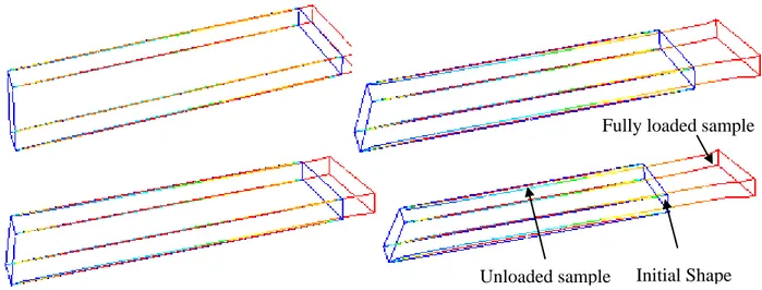
combination, in the same system, of strain (elastic part) and strain rate (viscous part) that allows us to test our methodology: a monolithic approach resolution, which can be analogically used for a viscoelastic problem and a classical fluid-structure interaction one being the main purpose of this work implementation of a solver that can treat both case. Moreover, with this model, elasticity is perfectly preserved, meaning that a deformed object must return to its original position upon unloading which can provide us relatively simple benchmarks.
Using the viscoelastic Kelvin-Voigt model, the stress tensor is defined as:
ve v e
(2.1)
whereeandvare the elastic and viscous stresses, respectively. In the simple linear case:
2 v v v pI (2.2)
2 e e u etr u I (2.3)wherevandpare the viscosity and the hydrostatic pressure, tr
. is the trace operator, I is theidentity tensor,
u and
v are the strain and the strain rate tensors, with
hdefined, in the linear case, as
1
2
t
The Lamé’s coefficients are defined as:
2 1 e e E (2.4) and
1
1 2
e e e e E (2.5)withEthe Young’s modulus,eis the Poisson’s ratio.
Since the viscoelastic model contains a “solid” behavior, so-called the elastic part and a “fluid” behavior, so-called the viscous part, the resolution of this system is similar to the resolution of a twophase problem, like in classical Fluid-Structure Interaction. Therefore, a brief introduction of viscoelasticity and FSI in the literature will enlighten our choice and our approach for its resolution.
2-Viscoelasticity and Fluid Structure Interaction (FSI)
20
2.1.1 An introduction to viscoelasticity
The properties (mechanical, electrical, optical, etc.) of polymers are often time dependent and cannot be treated mathematically by the simplest usual constitutive laws of either solids or fluids [15]. According to Rosen [37], two simple experiments allow illustrating viscoelasticity:
- Silly Putty: As bouncing putty, the material bounces when dropped but flow like a liquid when lying stationary. It has some characteristics of an elastic solid and some of a viscous fluid
- Weissenberg Effect: known also as rod-climbing experiment, this is a common phenomenon that occurs when a rod rotated into a solution of liquid polymer. In a visco elastic fluid the material climbs up the rod whereas in a Newtonian fluid dominating inertia effects would move the material away from the rod.
Another way of describing viscoelasticity is the fact that under a constant loading (resp. stretching) strain (resp. stress) depends upon time, which is often described as the fact that mechanical characteristics depend upon time. Specifically, the time dependent behavior of polymers is due to their molecular structure and the fact any deformation would involve conformational changes at different levels. This introduces a kind of memory effects which creates the need to characterize engineering properties in a manner different than those used for other structural materials.
A discussion of physically based approaches for visco elasticity is out of the scope of the present study. Let’s start at the point where mechanical effects of viscoelasticity have to be accounted for. The simplified vision according which deformation of polymers combines some reversible phenomena that are equivalent to those existing in an elastic solid and some others, time dependent and irreversible, that exist in a viscous fluid, is then good starting point.
In consequence, models are often depicted through simple analogical systems consisting of elastic elements (springs, which represent the elastic reversible part) and viscous elements (dashpots, which account for time dependent irreversible part). If one considers that global strain results from addition of individual strains, which are associated to the two contributions, serial models are proposed. If one assumes that global stress results from addition of individual stresses, parallel models are used.
Models are then built up via an a priori decomposition of the strain (resp. stress) into contributions that are either reversible or not and a combination of either the elementary strains or stresses. Additionally to that, one can distinguish two main levels, linear and not linear, of viscoelasticity. In the linear approaches the Boltzmann superposition principle [15] [38] is valid. It is usually applicable for small strains. However, the superposition principle often provides a useful first order approximation.
The non-linear viscoelasticity usually occurs when the deformations are large or when the properties of the material vary upon deformations. Two types of nonlinearities are to be distinguished: the material nonlinearities and the geometric nonlinearities. Material nonlinearities refer to nonlinear stress strain response that occurs due to the inherent constitutive response of the material, while geometric nonlinearities refer to mathematical issues that arise when displacements and strains become large and when the linearized definitions of stress and strain become irrelevant.
Characteristics, applications and properties of polymers
21
The isochronous response is linear for linear viscoelastic materials, but the stress-strain curves at different times are separated from one another. When a viscoelastic material behaves nonlinearly, the isochronous stress-strain curves begin to deviate from linearity at a certain stress level. In our work, even if starting with simple Kelvin-Voigt model to treat viscoelasticity, we here began to work on the implementation of a nonlinear model, by considering visco-hyper-elasticity.
2.1.2 Isochronous modulus vs. temperature behavior
The temperature plays an important role on the mechanical behavior of polymers. Two important temperatures are the glass transition temperature Tg (or second order transition temperature) and Tm, the melt temperature (or first order transition temperature) for semicrystalline material or the flowing temperature for amorphous materials. The need of an isochronous modulus-temperature curve as shown in Figure 2-1 is essential to determine the Tm and Tg. This figure illustrates the variation of the 10 second relaxation modulus with temperature for amorphous, crystalline and cross-linked polymers [15]. Usually, we distinguish four zones: glassy, transition, rubbery and flow regions.
- In the glassy state, polymers are rigid with high modules that can reach 1 GPa. The behavior of the polymer is slightly visco elastic and there is often evidence for visco plasticity at higher strains. At the lower temperatures the material become brittle.
- In the glass transition zone, viscoelastic effects become predominant, plastic processes disappear progressively and hyper elasticity progressively takes place. The transition temperature Tg corresponding to the limit between glassy and rubbery state.
- In the rubbery state, the stiffness modulus reaches a lower limit, and rupture deformations are larger. In this phase, strain is mainly reversible though not totally elastic when polymer is not crosslinked. In any case elastic part is rather representative for not linear hyper elasticity than glassy enthalpy elasticity.
Figure 2-1: E (10 Sec.) for a crystalline polystyrene (A), a lightly cross-linked polystyrene (B), and amorphous polystyrene (C) [15].
2-Viscoelasticity and Fluid Structure Interaction (FSI)
22
The Tg is an important descriptor of polymer thermo-mechanical response. This factor is a fundamental measurement of the molecular mobility, and of the effect such as effect of absorbed diluents, expansive stress states, and lack of bulky molecular groups.
2.1.3 Phenomenological mechanical models
The time dependence of viscoelastic response is analogous to the time dependence of reactive electrical circuits, and both can be described by identical ordinary differential equations in time. A convenient way to develop these relations is by employing “spring-dashpot” models. In the following section, we will see the simplest “spring-dashpot” models.
2.1.3.1 Linear viscoelasticity
We remind briefly in the following the three simplest linear viscoelastic models: the Maxwell’s model, the Kelvin-Voigt’s model and the Zener’s model [39]. We start with the Maxwell model, represented by a purely viscous damper and a purely elastic spring connected in series, as shown in the Figure 2-2:
Figure 2-2: Schematic representation of Maxwell model.
At timetthe strain in the spring is1and that of the dashpot2, while the stress on each element is
the same and equal to the imposed stress:
1
2 2 1 1 d d E dt dt (2.6)since the total strain is the sum of the strain in each element:
1 2 t E (2.7)
This model is able to reproduce partly the relaxation. In that case for a given constant strain, : exp r t E t (2.8) withtr E , a relaxation time.
However, Maxwell model cannot predict creep, which can be partly reproduced using Kelvin– Voigt’s model, also known as the Voigt model (Figure 2-3). In that case stress results from the addition of individual stress in each branch:
1 2
(2.9)
Characteristics, applications and properties of polymers 23 1 d dt and 2 E (2.10)
Figure 2-3: Schematic representation of the Kelvin–Voigt model.
In the case of a creep test (stress kept constant at ):
1 exp r t E t (2.11)
Contrary to Maxwell’s model, Kelvin-Voigt’s model is not relevant in case of relaxation.
To model more than one viscoelastic phenomenon authors generally combine those simple or those generalized models. Amongst simplest approach, let’s quote Burgers’ model (Figure 2-4) as an example that involves a springE1, in series with a Kelvin-Voigt’s element withE2and2, and
with a dashpot1, as shown in the following Figure 2-6.
Figure 2-4: Schematic representation of the Burgers model.
Under a constant stress left the spring account for a strain:
1 1
E
(2.12)
At the same time the strain in the Kelvin-Voigt element is:
2 2 2 2 1 exp E t E (2.13)
Finally strain of the right dashpot is:
3 1 t (2.14)
2-Viscoelasticity and Fluid Structure Interaction (FSI) 24 1 2 1 1 1 1 exp r
elastic delayed elastic flow
t t E E t (2.15) with 2 2 r t E which means
- spontaneous elastic deformation,
- delayed elastic deformation, or reversible creep, - irreversible creep (flow)
Parallel to that, both the two approaches allow defining one unique relaxation time. Due to the complexity of the polymers structure, especially semi-crystalline, one unique relaxation time is not enough to represent all the observed viscoelastic phenomena. Combining several of these elementary models in a parallel (in case of Maxwell’s model) or in a serial (in case of Voigt’s model) manner defines so-called generalized Maxwell (Figure 2-5) or generalized Kelvin-Voigt (Figure 2-6) models and allow reproducing time relaxation distribution,tr i, .
Figure 2-5: Generalized Maxwell model.
In case of genberalized Maxwelle model one can reproduce relaxation as:
1 2
,1 ,2 ,
exp exp iexp
r r r i t t t E E E t t t (2.16)
Characteristics, applications and properties of polymers
25
Whilst creep can be reproduced using generalized Voigt model.
1 ,1 2 ,2 ,
1 1 1
1 exp 1 exp 1 exp
r r i r i t t t E t E t E t (2.17)
To be complete let’s also emphasize that this review is far from complete. Authors often combine those basic concepts (generalization and combination of Maxwell and Voigt elements) to reproduce experimental observations.
Introducing nonlinear springs or dashpot at one level or another allows accounting for material nonlinearity. Some physically based approaches also exist. Built up within the frame of chain statistic elastic dumbbell strategy leads to results equivalent to Maxwell’s model. Network and reptation theories lead to more complex model [40]. Those models manipulate different parameters, namely entanglements density, chain length instead of modulus and viscosity. Obviously one has also to keep in mind that all involves parameters should depend on temperature. Nevertheless, at this stage simple models are rich enough to enlighten numerical difficulties and to validate feasibility of our proposal, and that is why the Kelvin-Voigt model is chosen to illustrate our numerical even it is going to be applied to
- elastic or hyper-elastic, - viscous,
- viscoelastic,
- visco-hyper-elastic,
simple test cases. In the following, combination of viscous and elastic scheme through a FSI approach in the literature will be summarized.
2-Viscoelasticity and Fluid Structure Interaction (FSI)
26
2.2
Fluid structure interaction (FSI) numerical approaches review
Fluid-structure interaction phenomena are present in many domains of modern engineering such as nuclear, aerospace, civil engineering, shipbuilding and biomechanics domains. In the last three decades, there has been an increasing interest for the simulation of these problems. Nevertheless, the purpose of this literature review is to focus on FSI problem between an incompressible Newtonian fluid and a compressible elastic structure to study efficient numerical methods to model the viscoelastic behavior.
Firstly, we present the FSI problem in a general context. Afterwards, we introduce the numerical methods to solve this problem with its advantages and disadvantages.
2.2.1 Fluid-Structure formulation
We consider a homogeneous linear elastic solids, immerged in a computational domain Ω and
surrounded by a fluid domainf, assumed to be incompressible Newtonian. 2.2.1.1 Mechanical characteristics in the solid
The local formulation of the problem is:
2 2 / in in s s s s s imposed s s imposed f s σ u u or d u f dt σ .n f
(2.18)where u,sand f are the displacement of point in the solid, the density and the exterior force s
applied to the solid, respectively. σ is described as the Cauchy stress tensors
2 ( ) ( )
e e u etr u I
, related to the displacement by a constitutive model (linear elastic).
/
f s
, fimposedanduimposedrepresent the fluid-solid interface, the boundary force and the boundary
displacement. n is the vector normal to the solid interface. s
2.2.1.2 Mechanical characteristics in the fluid
The fluid is assumed to be homogeneous, Newtonian and incompressible. The local formulation of the problem is described by the Navier-Stokes equations below:
/ ( ) 0 . . f f f f f imposed f f imposed f f s v v v f in t v in v v or n n in (2.19)
where v,fand ffare the velocity, the fluid density and the exterior force in the fluid. The stress
tensor in the fluid is defined as:
2 ( )
f f v pI
Fluid structure interaction (FSI)
27 2.2.1.3 Fluid-Structure interface conditions
The coupling of the structure and the fluid occurs at the interfacef s/ . Therefore, the interface conditions are needed to ensure the continuity of velocity and of the interface force. These conditions can be resumed as following:
in . . f / s f f s s du v dt n n (2.21)
The fluid-structure interactions are part of the simulation of the behavior where the environment contains two phases. Indeed, the simulation of this environment type requires defining a behavior for the fluid, another for the structure and an interaction model between the two phases.
2.2.2 Fluid-structure coupling: monolithic vs. partitioned coupling
Coupling is the energy conservative transfer between two systems through an interface. In the literature, two coupling types are suggested: the monolithic coupling and the partitioned coupling. In a monolithic coupling, fluid and structure equations are solved in the same system, it means that the mechanical problems in the fluid and in the solid are simultaneously computed. This method was applied, by Walhorn et al. [41] [42] to FSI problems involving free surface waves using a space-time finite element discretization. It was used also to solve a multiphase problem [43] with pretty good results in the case of a two phases problem (fluid-fluid or fluid-rigid). This coupling gives unconditional stability of the coupling scheme, the time step is limited only by the required accuracy, therefore convergence to the solution is optimal [44] [45] [46].
This method consists of a fully explicit coupling with an alternative exchange between the fluid and the structure solver in each instant via the boundary conditions. The partitioned coupling allows using the computation specific to each environment. However, this method may induce problems in controlling interface and in precision and stability of the calculation [44] [46] [47]. Let us emphasize that a partitioned coupling is not necessarily a weak coupling since the continuity conditions can be strengthened. Recently, a strong partitioned coupling FSI [48] [49] has been developed to solve the problem keeping the robustness and effectiveness of the original approach.
Monolithic coupling for large-displacement FSI problems is often thought to be more robust than the partitioned coupling, but often too expensive both in terms of memory and in terms of CPU time requirements. However, Heil and co-workers [44] demonstrated these beliefs to be at least sometimes unjustified. They studied the relative efficiencies of the partitioned and of the monolithic coupling in the case where the fluid is Newtonian and incompressible. First, results showed that the monolithic solver performs better when the coupling is strong and the partitioned solver performs better for a weak coupling. Nevertheless, for the steady solutions computed here, both methods are competitive. Heil [44] demonstrated that monolithic solvers are competitive even for problems in which the fluid–solid coupling is weak. When the fluid-structure is strong, severe convergence problems appear with the partitioned solvers and the monolithic solvers are advantageous. However, for large problems, particularly in 3D, the effective use of monolithic solvers requires efficient preconditioning of the iterative solving of the large linear systems associated to the fully coupled system of nonlinear algebraic equations by the Newton’s method.
2-Viscoelasticity and Fluid Structure Interaction (FSI)
28
Figure 2-7: The piston problem (interface region expanded for clarity) [46].
Moreover, for a 1D model of a piston interacting with a fluid (Figure 2-7), Hulshoff and al. [46] made a comparison of the two types of coupling in terms of stability, accuracy and computational cost. They demonstrated that the time step controls the stability of the partitioned method. On the other hand, no restriction exists for the monolithic method so that the time step is only limited by the wished accuracy of the calculation. However, for a given accuracy [46] time steps required by the partitioned method are smaller than those of the monolithic method. Consequently, for a certain level of accuracy, a monolithic approach can be a reasonable solution. Furthermore, there is a potential for reducing their computational cost (the monolithic method is still three to four times higher than the one of the partitioned method), which only needs a single fluid-structure iteration per time step in this simulation.
Choosing between partitioned and monolithic approaches is then not a simple task and may depend on the context. The monolithic approach is often more robust and more accurate than the partitioned method and ensures unconditional stability. However, this method is costly in terms of memory and computing time. So, there is an intermediate strategy to combine the benefits (and to avoid the disadvantages) of these two extreme cases. A possible technique is to choose a partitioned explicit algorithm and to make it more robust and less restrictive towards the time step criteria by using an iterative predictor-corrector type. However, a key issue of the FSI problem is the interfaces treatment, the difficulty being to ensure the conditions described in section 2.2.1.3, especially on moving interfaces. The next section will concern the resolution of this problem.
2.2.2.1 FSI resolution
In most cases, FSI is solved using the finite element or the finite volume method. However, meshless methods are also used. Like the SPH method (Smooth Particle Hydrodynamics) developed by Gingold et al. [50] and the PFEM method (Particle Finite Element Method, considered as a special class of meshless methods) [51] [52]. Recently, several studies used the XFEM (eXtended Finite Element Method) method which revealed advantages but also weaknesses in comparison with FEM [53].
In general, meshless methods have considerable flexibility regarding the easiness to add or to remove particles following the evolution of the simulation, without updating the data structure. In addition, as the shape functions are less dependent on the disposal of discretization points, problems due to large deformations are less sensitive in that case. However, whatever the method is, searching for the nearest neighbors is an expensive process, to be performed at all integration points in the numerical integration of the variational problem. The FEM is much less costly thanks to the exact integration in the space of polynomial function. Then, the integration error is zero. Integration points are placed regularly in each finite element. Conversely, the notion of element does not exist in the meshfree methods. Same formulas can be used for integration, but due to a lack of accuracy more integration points are needed to minimize the error. For convenience, we will not use these meshless methods, only the FEM is considered. The fluid problem is generally solved in the literature by an Eulerian formulation where the computational domain remains fixed over time, while a Lagrangian formulation with the deformation of structure domain is used for
Fluid structure interaction (FSI)
29
the structure problem. However, in a FSI problem which combines the whole fluid and structure problem in a same system, an adaptive approach which satisfies and takes the advantages of the two methods is of prime interest. Whatever the chosen method for fluid-structure coupling, the difficulties are related to the prediction of fluid-structure interface. In practice, authors use a fixed or mobile mesh techniques.
2.2.2.2 Dynamic mesh
Figure 2-8: Referential Lagrangian, Eulerian and ALE [54].
2.2.2.2.1 Moving mesh
The domain is discretized by a moving mesh in order to follow the motion of the fluid-structure interface. In this context, we can use a Lagrangian formulation where the bodies motion is considered as volume elements which are carried along with the body in a known reference. The reference system is attached to the volume elements.
In the Lagrangian formulation (Figure 2-8), each node is linked to the same material particle throughout the deformation process. An interesting numerical advantage of this approach is the negligible convective terms in the integrated constitutive equations. Moreover, following the boundary becomes easier than in the case of the Eulerian formulation. However, in the large deformations, the mesh can be largely distorted and lead to inaccurate results, or endanger the simulation. In this case, remeshing is required but this step is usually expensive.
Among existing numerical methods, Arbitrary Eulerian-Lagrangian method (ALE) is widely used as an alternative solution. Full explanation can be found in [54] [55] [56] [57] [58]. The ALE formulation (Figure 2-8) combines the advantages of the Lagrangian formulation (accurate
Lagrangian description Eulerian description ALE description t vf t Particles material Mesh node vf t vale
2-Viscoelasticity and Fluid Structure Interaction (FSI)
30
boundary representation, easiness to impose boundary conditions) and those of the Eulerian formulation (for large distortion case). The principle of the ALE formulation is to describe the fluid equations in an arbitrary reference by introducing an arbitrary velocity of the mesh. This reference is a generalization of the Lagrangian and Eulerian frameworks. The arbitrary velocity can deform the domain according to the mesh node position. Concretely, when the nodes are far from the mobile interface, the arbitrary velocity tends to zero such as in the approach tends to an Eulerian approach. On the other hand, when these nodes are near the interface, the arbitrary velocity tends to the velocity of the interface, which corresponds to Lagrangian approach. In between those two zones, intermediate velocities are applied that ensure the deformation is smooth (Figure 2-9). Applying this approach to the incompressible Newtonian fluid leads to equation (2.22): / ( ( ) ) in 0 in . . in f ale f f f f imposed f f imposed f f s v v v v f t v v v et n n (2.22)
wherevaleis the arbitrary velocity of the material point, which represents the deformation velocity
of the mesh. One can check that vale0 corresponds to the Eulerian description and valev to the
Lagrangian description.
Initial mesh Lagrangian formulation ALE formulation (deformed mesh) (deformed mesh)
Figure 2-9: Evolution of the mesh following the implemented formulation [58].
The ALE method is quite simple to implement and accurate. However if the deformation, displacement or rotation of the solid is too large, the mesh can be largely distorted, which affects the accuracy of the solution. We can then use mesh adaptation, which causes a significant computational cost.
2.2.2.2.2 Fixed mesh
The computational domain remains fixed, and it is then necessary to model boundaries and boundary conditions to monitor the interface over time within this mesh. Among all numerical method using a fixed mesh, Eulerian formulations are widely used in fluid mechanics or in the stationary materials forming. This method considers volume elements at fixed locations in space, across which material flows. The reference system is fixed. The Eulerian formulation introduces difficulties in problems where the boundaries are variables. It is a great difficulty to take into account the physical boundary conditions and an accurate definition of physical borders when they change over time. In contrast, Eulerian formulations allow a significant distortion of the material.
The Immersed Boundary method (IB) developed by Peskin [59] can also be mentioned. The advantage of this method is to use a fixed Cartesian grid for the fluid domain and a fully
Fluid structure interaction (FSI)
31
independent structure immersed in the fluid. The fluid-structure interaction is made by the nodal distribution forces and nodal velocity interpolation between Eulerian and Lagrangian domain on the volume using an approximation of the Dirac delta function. The Dirac function is operated in two different stages in the IB algorithm: the first step defines the action-reaction effect, imposing the conservation of forces at the interface, and the second results in the kinematic condition: the structure itself even has to move at the same velocity as the liquid around it. This function shall be continuous to avoid the jump in velocity and in applied forces in the immerged structure or the applied forces. This ensures also that the moment of forces through the interface is maintained. Several methods based on the IB method have been developed to solve the FSI problem, such as Immersed Finite Element Method (IFEM) [60], Extended Immersed Boundary Method (EIBM) [61], Immersed Interface Method [62] and Fictitious Domain Method [63]. These methods allow large displacements and can be coupled with ALE formulation [64] [65].
Loon and co-workers [66] [67] [68]compared the ALE method and the fictitious domain/ALE coupling in the deformed thin solid case. They concluded that, depending on the problem, the ALE method is probably preferable to other approaches; however, a remeshing tool is required. The algorithm is robust, accurate without excess of degrees of freedom. However, the fictitious domains method is a wise choice when deformation, displacement or rotation of the solid is large. We might choose to use the coupling fictitious domain/adaptation on the required accuracy. Figure 2-10 shows the results obtained by Van Loon et al. [68] for the pressure drop through a plastic membrane using the fictitious domain with and without mesh adaptation.
Figure 2-10: Pressure drop over a membrane using the fictitious domain method without mesh adaptation (a) and with mesh adaptation (b) (showing the velocity vector field) [68].
2.2.2.3 Determining interfaces
Numerical techniques used in the context of fluid-structure interaction are based on the natural representation of the interface between the two environments, that can be represented through sharp-interface models and diffuse interface models (either two-phase or mixed) (Figure 2-11).
2-Viscoelasticity and Fluid Structure Interaction (FSI)
32
Figure 2-11: Illustration of the sharp-interface, and two-phase and mixture diffuse-interface approaches [69].
In diffuse interface methods, a popular tool for simulation of two-phase flows, interface between the two phases is considered as having a finite width and is characterized by rapid but smooth transitions in the density, viscosity, and other physical quantities. The two-phase model has been discussed in [70] [69], and its performance is compared to those of the mixture model.
If the mesh of the computational domain is fixed, a specific function is required for locating the interface. Two types of computation techniques exist in the literature that are support by the finite elements. The first consists in capturing the geometry of the surface; an example of this type is the level-set method. The second consists on accepting a loss of certain information: such is in the case of volume of fluid method (VOF). The latter methods are sometimes or always associated with diffuse interface approaches.
2.2.2.3.1 Volume of fluid
This method is based on the value of the volume fraction occupied by a phase within an element. This method is considered an ascendant of the earlier MAC methods (Marker and Cell), SLICE method (Simple Line Interface Calculation), or the method PLIC (Piecewise Linear Interface Calculation). A brief idea of these methods is introduced in [56].
2.2.2.3.2 Level-Set
The standard Level-Set method is proposed by Osher and Sethian [71], and it has been used to transport the interfaces between the different phases. Its motion is then described by:
![Figure 2-10: Pressure drop over a membrane using the fictitious domain method without mesh adaptation (a) and with mesh adaptation (b) (showing the velocity vector field) [68]](https://thumb-eu.123doks.com/thumbv2/123doknet/2993227.83844/32.893.172.758.606.773/figure-pressure-membrane-fictitious-adaptation-adaptation-showing-velocity.webp)
![Figure 2-11: Illustration of the sharp-interface, and two-phase and mixture diffuse-interface approaches [69]](https://thumb-eu.123doks.com/thumbv2/123doknet/2993227.83844/33.893.195.680.134.458/figure-illustration-sharp-interface-mixture-diffuse-interface-approaches.webp)