HAL Id: hal-02467122
https://hal.inria.fr/hal-02467122
Submitted on 4 Feb 2020
HAL is a multi-disciplinary open access
archive for the deposit and dissemination of
sci-entific research documents, whether they are
pub-lished or not. The documents may come from
teaching and research institutions in France or
abroad, or from public or private research centers.
L’archive ouverte pluridisciplinaire HAL, est
destinée au dépôt et à la diffusion de documents
scientifiques de niveau recherche, publiés ou non,
émanant des établissements d’enseignement et de
recherche français ou étrangers, des laboratoires
publics ou privés.
An image driven vision-based control framework for
wheeled mobile robots
G Blanc, Y. Mezouar, Philippe Martinet
To cite this version:
G Blanc, Y. Mezouar, Philippe Martinet. An image driven vision-based control framework for wheeled
mobile robots. International Symposium on Robotics and Automation, ISRA’04, Aug 2004, Queretaro,
Mexico. pp.507-512. �hal-02467122�
An image driven vision-based control framework
for wheeled mobile robots
G. Blanc, Y. Mezouar and P. Martinet
LASMEA
UBP Clermont-Ferrand II, UMR 6602 du CNRS 24 avenue des Landais, 63177 AUBIERE -FRANCE Email: gblanc,mezouar,[email protected]
Abstract— We deal in this paper with an original visual
servoing method intended to control a nonholonomic wheeled mobile robot. These works are a part of a complete image-based framework for navigation of a mobile robot, using only a monocular vision system embedded on the robot. The navigation system uses a set of relay images to enable the robot to reach a goal configuration expressed as a desired attitude of visual landmarks in the image plane. This paper particularly focuses on a suitable image-based control law of a nonholonomic robot for navigating in image database, with the assumption that the ground is obstacle free. We show how computing a suitable homographic transformation between the current camera image and a desired one allows to estimate an error vector on the state of the robot relative to a virtual straight line. This line is joined and followed thanks to a control law designed according to a well suited chained system of the state of the robot. Simulations illustrate this point, and experimental results for a two wheels driven robot confirm the validity of our approach.
I. INTRODUCTION
Navigation of a mobile robot includes many sub-tasks which are strongly dependent on each other. Given a global task of navigation, perception and control systems are used to make the robot succeed on it. From a perception module, with proprioceptive and/or exteroceptive sensors, a representation of the robot environment can be built, and it is then possible to locate the robot into this representation using the same perception system. This localisation allows to planify and generates adequated motions to achieve the specified task. Clearly, embedded sensors play a central role. Sonar and laser were the first sensors used for wheeled mobile robots navigation. More recently, the advent of fast and inexpensive digital imaging technology has allowed camera systems to be integrated as part of navigation systems. Given the advantages and shortcomings of each sensor, navigation approaches based on the fusion of observations provided by various sensors has been explored [3].
Computer vision can provide a powerful way of sensing the environment and controlling the robot motions. It is thus not surprising that more recent works have focused on the use of conventional or omnidirectional cameras as main sensors to navigate in partially or totally unknown environments. Indoor navigation tasks give a rise to a particular interest. Such workspaces are complex but well structured. Strong hypothesis such as parallelism of the floor and the ceiling or verticality of walls are generally respected. Such constraints are useful
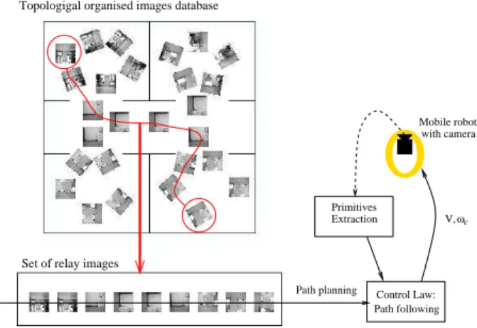
Topologigal organised images database
Set of relay images
Path planning Mobile robot V,ωc with camera Path following Control Law: Primitives Extraction
Fig. 1. Global strategy for indoor navigation
for 3D pose reconstruction methods, which allow the camera to be used as a global positioning system to locate the robot with respect to the observed environment. In order to obtain the 3D pose of the camera, several types of features can be used, such as straight lines [1] or rectangular patterns [8].
From the control point of view, this kind of localization sys-tems is useful because it allows to use directly state feedback based control laws designed for nonholomic robots [10], which are proved asymptotically stable. A learn or planned path can be replayed with a control law adapted to path following, as it is done in [16] with a CP-DGPS.
In our approach, the whole problem of navigation of a mobile robot is formulated in the camera image space, as described in [2] and represented by Fig.1. Given an image database describing the robot environment, the robot motions are controlled from its current position to a desired one, spec-ified through a target image selected in the image database. The image database is obtained and indexed off-line during a supervised learning step, and constitutes a visual memory of the robot. The contents of this memory is thus a set of images which provide a representative sample of all the points of view which could be reached during the displacement phase. When the robot is let staying at an unspecified place of its workspace, we determine which image of the memory is the closest from the observed one. This can be done, as Remazeilles and al propose in [14], by comparing the photometric invariants of the
request image with those of the images of the visual memory. The task is specified as a target image to reach, chosen among the images of the database. A set of relay images describing a path from the current to the goal locations of the robot is then obtained thanks to the topological indexing of the database. The last step of this framework concerns the control scheme to bring an image of the given set to the next one and so on. This is the object of this paper.
The use of relay images to achieve large displacement positioning tasks is a promising approach. In [13], the authors propose a multi-images framework to control the 6 dof of a robotic arm. The stabilization to a point is reformulated as a trajectory following in the image space through key images. Tsakiris et al [17] have pointed out that image-based visual servoing techniques can be extended to nonholonomic mobile robots by adding degrees of freedom to the hand-eye system. The authors propose to embed the visual servoing control scheme in the task function formalism. Vision-based mobile robotic tasks such as wall following or self positioning with respect to landmarks is thus possible using this framework [9]. Control laws for specific tasks have been developed, as for path following, if these extra degrees of freedom are not available. These methods relies on the uncoupling of the lateral and longitudinal control. Yi Ma et al present in [11] a theoretical framework to regulate the orientation of a wheeled mobile robot with respect to a ground curve using a single camera, by expressing in the image a state vector extracted from optical flow. More recently, motivated by the development of 2D 1/2 visual-servoing method proposed by Malis et al (see [12]), some authors have investigated the use of homography estimation and epipolar geometry of the scene for visual-servoing of mobile robots.
In [6] and [5], a partial estimation of the camera displacement between the current and desired views is used to design control laws. The camera displacement is estimated by uncoupling translation and rotation components of an homography matrix. In [6], a time-varying control allows an asymptotic stabilisa-tion on a desired image. In [5], a trajectory following task is achieved. The trajectory to follow is defined by a prerecorded video and the control law is proved stable using Lyapunov-based analysis.
In our case, as a difference with a whole video sequence, we deal with a set of relay images which have been acquired from geometrically spaced out point of view. As a consequence, we design an homography-based visual-servoing control law appropriated to large displacements, i.e where the initial error is large. The authors of [13] and [14] deal with this issue for a manipulator robot. Taking into account the nonholomic constraints of wheeled mobile robots, we propose a suitable formulation of our problem as a path following, with the assumption that the evolution plane of the robot is obstacle free. We show that computing a suitable planar homography between the current image and the next relay one allows to design a path connecting these images. This path can then be followed using a suitable control law. We propose to uncouple guidance and longitudinal control thanks to a chained form
of the kinematics of the system. Leaving the longitudinal speed free allows more flexibility for the navigation task. In this paper, the evolved theory is illustrated in an indoor environment. However, other applications could be considered, as navigation of urban vehicles, which should move in a structured environment at low velocities.
The remainder of this paper is organized as follows. In Section II, the problem we address and the models used through the paper are described. The Section III is devoted to the control law design. As an example of the generic proposed framework, the particular case of indoor navigation with a camera looking at the ceiling is treated in Section IV. In Section V, simulation and experimental results which confirm the validity of the proposed approach are presented.
II. PROBLEM FORMULATION AND MODELS
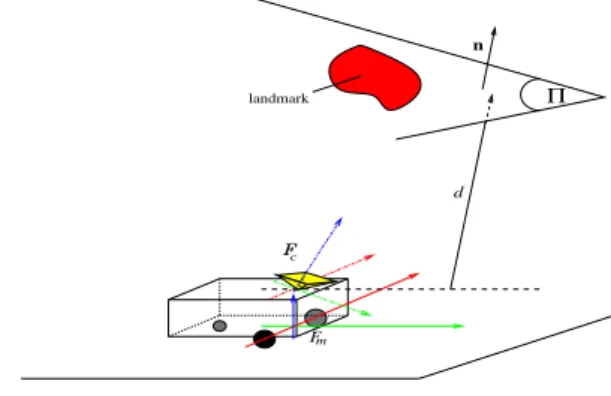
Throughout the paper, we consider a nonholonomic system with unicycle kinematics. Let Fc and Fm be the frames
attached to the camera and to the mobile robot respectively and consider a plane Π on which is lying some natural or artificial landmarks. We note Fc∗ the desired frame corresponding to the camera pose from which a relay image I∗ was shot. Our aim is to bring Fc to Fc∗ by moving the mobile robot along
a nonholonomic path. landmark Π n Fm Fc d
Fig. 2. Considered setup
A. Geometric relations
The plane Π is supposed to contain some landmarks which can be tracked in the image I and are identified in I∗. Let P be a set of points lying on one of these landmarks L in I, and P∗ the set of corresponding points in I∗. pi=
£
ui vi 1 ¤>, and p∗i =£ u∗i vi∗ 1 ¤> denote the homogeneous coordi-nates in pixel of each point lying on P and P∗ respectively. mi = £ xi yi 1 ¤> and m∗i = £ x∗ i y∗i 1 ¤> are the corresponding homogeneous coordinates in meter. A projective homography matrix G related to Π maps the points pi and
p∗ i:
αpi = Gp∗i (1)
where α is a non zero scalar. If at least i ≥ 4, it is well known that G can be estimated by solving a linear system. In the remainder of this paper, the internal parameters matrix K of the camera is assumed to be known. Then the Euclidean
homography can be computed up to a non zero scalar factor
α:
αH = K−1GK (2)
Let us define Π in Fc∗by£ n∗> d∗ ¤where d is a constant
distance from Π to the origin of Fc∗ , and n∗> is the unitary normal vector to Π in Fc. The Euclidean homography matrix
H can be decomposed into a rotation and a rank 1 matrix: H = R + tn
∗>
d∗ (3)
R and t are the rotation matrix and the translation vector that compose the homogeneous rigid transformation between Fc
and Fc∗. Note that when Fc is confounded with Fc∗, H is
proportional to the identity matrix. Finally, let us note that it is possible to compute the homography matrix in the more general case where at least the projection of eight 3D points are matched in I and I∗.
B. Canonical camera configuration
First, consider that the camera frame Fc is confounded
with the control frame. In this configuration, which is named canonical in the sequel, the camera optical axis coincides with the rotation axis of the mobile robot and the camera optical center is the axle midpoint of the mobile robot. The camera frame and the mobile robot are thus subjected to the same kinematic nonholonomic constraints. Considering that the robot is moving on a perfect horizontal plane without any incidence on the image of the dynamics of the mechanical structure, what can be assumed if the robot moves enough slowly, the R matrix is reduced to a simple rotation matrix around the optical axis, and t has only two degrees of freedom on the ground plane. As exposed in [7], it is possible from H to determine the camera motion parameters, it means the rotation R and the scalar translation vector dt∗. The normal
vector n∗ can also be determined, but the results are better if n∗ has been previously well estimated, as in the case of indoor navigation with a camera looking at the ceiling.
C. General camera configuration
Of course, in real cases the camera frame Fc often presents
a 6 degrees of freedom rigid transformation with respect to the robot frame Fm. However we will show that it is
possible to come down to the simple configuration previously described where Fc and Fm are coincident (refer to II-B).
Consider a virtual camera in the previously canonical camera configuration and let us note Fv= Fma frame attached on it,
and Iv its image plane. Let Rmand tmbe the rotation matrix
and the translation vector between Fc and Fv = Fm. They
are mechanically fixed and represent the hand-eye camera parameters. As exposed in section II-A, an homography related to Π ties up I and Iv. The points pi and p∗i can thus be
projected in the virtual camera image through the constant homography Hm from the knowledge of Rm, tm and n∗.
The problem of controlling the motions of the mobile robot using features extracted from the image of the real camera can thus be reformulated as the control of the virtual camera.
Therefore, in the remainder of this paper, we deal with the canonical configuration of the camera, where Fcis in fact the
frame Fv above-mentioned.
III. CONTROL LAW DESIGN
Our aim is to generate robot motion in order to superimpose
I and I∗, what reverts to move F
c to Fc∗ with respect
to the unicycle-like nonholomic constraints assigned to Fc.
The kinematic screw of Fc is assumed to consist only of
a longitudinal speed V along the Xc axis and a rotational
velocity ωc around Zc. A. Design principle
In the previous section, we have seen that from the knowl-edge of matched points in a target image I∗ and the current image I, the relative displacement between Fc∗ and Fc can
be extracted as a rotation matrix R and a scaled translation vector dt∗. Since XcYc-axis of Fc and Fc∗ are supposed to
span a plane parallel to the ground plane, an estimation of the angular deviation θ between Fc∗ and Fc can be directly
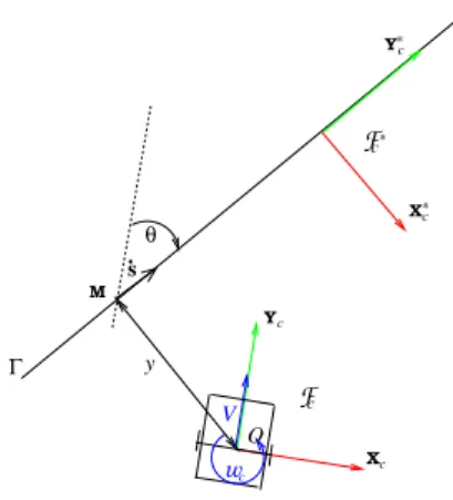
extracted from R. Consider a straight line Γ, parametrized according to the position Fc∗ and the Y∗c axis, as represented on Figure 3. We can get out from dt∗ the lateral deviation y up
to a scale factor between the origin of Fc and a straight line
Γ. As a consequence, the control problem can be formulated as following Γ in regulating to zero y and θ before the origin of Fc reaches the origin of Fc∗ (see Figure 3).
To achieve this control objective, chained systems properties are very interesting. A chained system results from a con-version of a mobile robot non linear model into an almost linear one [15]. As long as the robot longitudinal velocity
V is non zero, the performances of path following can be
determined in terms of settling distance [16]. In the considered cases, such a settling distance can be directly determined by the observed relative translations between Fc∗ and Fc at the
initial configuration. This property is exploited to ensure that
I and I∗ could be superimposed during the robot motion.
B. Control law design
s . Fc wc Xc Yc Yc Xc Fc* * * O y V θ M Γ
Fig. 3. Modelisation for control law design
In this part, a control law for straight line following is designed for cart-like vehicle moving on a perfect horizontal
plane under the conditions of pure rolling and non-slipping. Let us note ωv the cart angular velocity around the center of
its rear axle. We also define the point M as the orthogonal projection on Γ of the origin of Fc. A curvilinear coordinate s is associated to M on Γ. The state of the cart in its plane
of evolution is given by Xv=
£
s y θ ¤> (refer to Figure
3). The cart control vector is U = £ V ωc ¤>. These two vectors are related by the following state space model:
˙s = V cos θ ˙y = V sin θ ˙θ = ωc (4)
Of course this state description is derivated from the more general case where the robot is following a geometric path (see[15], and [16] for an applicative example). Let us now convert the state space model (4) into a chained system of dimension 3 £ a1 a2 a3
¤>
with a 2 dimensional control vector £ m1 m2
¤>
. The derivative of such a chained form with respect to time is:
˙ a1= m1 ˙ a2= a3m1 ˙ a3= m2 (5) The almost linearity of this system is then viewable when the chained system is derivated with respect to a1, with m3= m2m1:
a01= 1 a02= a3 a03= m3 (6)
Choosing a1 = s, the linear system (6) is independent from V , since it is driven by a variable homogeneous to the distance
covered by the robot. The input variable m1is given by (refer
to equations (4) and (5)):
m1= ˙s = V cos θ (7)
Let us now define a2= y. Then it comes:
˙
a2= V sin θ = a3m1 (8)
Therefore a3 must be chosen as:
a3= tan θ (9)
Consequently, a3 is not defined for θ = π2[π]. In the general
case of geometric path following, this condition is avoided by planning an appropriate path to follow. In our application, this can be avoided by choosing judiciously the relay images during the off-line learning step.
Finally, we deduce m2 from m2= ˙a3:
m2= ωc
cos2θ (10)
Thanks to the linearity of the chained system (6), a natural and simple expression for the control law is:
m3= −Kda3− Kpa2(Kp, Kd) ∈ R+2 (11)
This last relation combined to (6) leads to:
a002 + Kda 0
2+ Kpa2= 0 (12)
Consequently, both a2and a3converge to zero, independently
of the longitudinal velocity of the robot as long as V 6= 0. In view of a2= y and a3= tan θ, (11) ensures that both y and θ
converge to zero. Taking into account that V can be negative, the expression of m2= m3m1can be obtained from (11) and
it is given by:
m2= −|m1|Kda3− m1Kpa2 (13)
Therefore, ωc is extracted from (10) in which (13) is inserted: ωc(y, θ) = −V cos3θKpy − |V cos3θ|Kdtan θ (14)
The expression of the control vector U = £ V ωc ¤> can thus be computed. The guidance control law given by equation (14) has been designed independently of the longitudinal speed
V . As highlighted with equation (11), only Kp and Kd
theoretically set the performances of the control law. Then
V can be set to a constant value during all the motion or be
time-varying, seeing that V has to be non-zero.
The chained form consists in a double integrator (refer to (6)) and then the asymptotic stability of the control law (14) is guaranteed. In practice, the success of this control law relies on the gains Kp and Kd. Indeed, Kp and Kd determine the
dynamics of the second order system (12), i.e the impulse response of y with respect to the covered distance by the point M on Γ. An appropriate settling distance sr for the system
(12) can be set to a typical one for the considered application. The convergence of y and θ to zero before Fc reaches the
desired attitude Fc∗ should be ensured if the settling distance is chosen smaller than the distance between two shots of two consecutive images of the database.
IV. APPLICATION TO INDOOR NAVIGATION
Indoor environments abound in planes. Thus our framework should be well adapted to this kind of workspace. In this section, we address the particular application where Π is the ceiling, supposed to be parallel to the ground plane. In this case, the unitary normal vector n∗ to Π expressed in the canonical camera frame at a goal point of view Fc∗ is known to be n∗>= [0 0 1]. The Euclidean homography matrix H has thus a very simple expression (refer to equation (3)). Indeed, as the displacement between Fc∗ and Fc only consists of one
rotation θZc and two translations tXcXc and tY cYc, H is
given by (refer to equation (3)):
H =
cos θ − sin θ tsin θ cos θ tY cXc
0 0 1
(15)
Therefore, H has only three degrees of freedom. Only two points lying on Π and matched in I∗ and I are theoretically necessary to estimate H. From the computation of H, one can extract directly θ which is the angular deviation with respect to Γ introduced in section III. The lateral deviation y can also be estimated since it is the X∗c coordinate of the origin of Fc:
0 50 100 150 200 250 300 350 0 50 100 150 200 0 50 100 150 200 250 300 350 50 100 150 200 250 300 (a) (b)
Fig. 4. Visual features trajectories: (a) in the real camera image, (b) in the virtual camera image. Rounds are the initial features, squares are the desired ones.
Thus, from the computation of the Euclidean homography H, the state of Fc with respect to the straight line Γ can easily
be determined. The guidance control law designed in section III for a nonholonomic vehicle is then supplied. The next section illustrate and validate our approach with simulations and experimental results.
V. RESULTS
The proposed approach has been first tested in a simulation environment. In these simulations, both the vision system and the robotic plateform are assumed to be time-continuous, with a view to validating our approach from a theoretical point of view. The robotic task consists of moving the robot to a certain pose with respect to features in the desired image. The camera is embedded on the mobile robot and its optical center is positioned vertically with respect to the rear axle midpoint. A tilt angle of 0.1rad and a pan one of 0.01rad are introduced between the optical axis and the vertical axis of the frame attached to the mobile robot. The coordinates of the camera optical center with respect to Fmare 0.01m, 0.01m and 0.1m
along Xm, Ym and Zm respectively. The camera is looking
at three points. The control law presented in Section III is used to control the mobile robot. Figure 4 presents the visual features trajectories in the image plane: (a) curves are plotted in the real image plane, (b) curves are plotted in the virtual image plane.
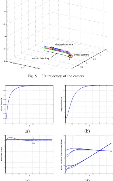
We first note that the paths described by the features converge to the desired positions. As can be shown in the Figure 5, the corresponding camera path confirms the validity of the control law. We can also notice that the mobile robot joins a straight line in the ground plane before passing through its desired attitude. As shown in Figure 6 (a) and (b), angular and lateral deviations of the robot are well regulated to zero. When the straight line is joined, the mobile robot stops rotating and follows straightly the path (Figure 6 (c)). However, we state that the mobile robot runs with a constant value of longitudinal velocity and it is not stopped-dead on the desired configuration. This is an inherent issue to the chained systems, which impose V 6= 0. That explains why the error in image points coordinates increases after having converged to zero (See Figure 6 (d)). Nevertheless, we do not mind this point when the reached configuration corresponds to a relay image. It is more cumbersome for the last step of stabilisation on the
−1.5 −1 −0.5 0 0.5 1 1.5 −1 −0.5 0 0.5 1 0 0.5 1 1.5 2 2.5 desired camera initial camera robot trajectory landmarks
Fig. 5. 3D trajectory of the camera
0 0.2 0.4 0.6 0.8 1 1.2 1.4 −0.16 −0.14 −0.12 −0.1 −0.08 −0.06 −0.04 −0.02 0 s lateral deviation 0 0.2 0.4 0.6 0.8 1 1.2 1.4 −1.4 −1.2 −1 −0.8 −0.6 −0.4 −0.2 0 s angular deviation (a) (b) 0 0.2 0.4 0.6 0.8 1 1.2 1.4 −3 −2.5 −2 −1.5 −1 −0.5 0 0.5 s kinematic screw ω V c 0 0.2 0.4 0.6 0.8 1 1.2 1.4 −150 −100 −50 0 50 100 s
errors on visual features coordinates
(c) (d)
Fig. 6. Signals with respect to s: (a) lateral deviation (m), (b) angular deviation (rad), (c) mobile robot kinematic screw (V in m.sec−1, ωc in
rad.sec−1), (d) behavior of the landmark points coordinates relatively to
their desired position (m)
goal image. Indeed, we ought to have an open loop step to stop the robot, what can not ensures an accurate final pose. In view of these results, the proposed approach has been tested on a PekeeT M robot from Wany Robotics. A 1/3” CMOS embedded camera is turned to the ceiling and is approximatively placed on the canonical configuration exposed in subsection II-B. Only a motors speed regulation runs on the main electronic card of the robot. The whole application, from image acquisition to the control law computation, is processed at the rate of 25Hz on a external 1.8GHz PC. Thanks to a robust tracking based on particular filter (see [4]), a set of four points lying on the ceiling is available at each image acquisition. The desired positions of these points are extracted from the relay image to reach. The two wheels driven robot is modeled as a unicycle. The length of the total displacement done on the ground plane is about 1.5m. The real initial
3D angular and lateral deviations, with respect to the desired attitude of the robot are respectively 0.5rad and 0.6m. The control gains Kp and Kd have been chosen for a settling distance of 0.7m (refer to equation (11)).
0 50 100 150 200 250 300 350 0 50 100 150 200 −80 −60 −40 −20 0 20 40 60 80 100 −60 −50 −40 −30 −20 −10 0 10 20 (a) (b)
Fig. 7. (a) Tracked points trajectories in the image. Rounds are the initial features, squares are the desired ones.(b) behavior of the tracked points coordinates relatively to their desired position.
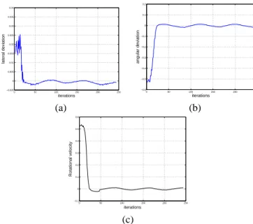
0 50 100 150 200 250 −0.005 0 0.005 0.01 0.015 0.02 0.025 0.03 0.035 0.04 iterations lateral deviation 0 50 100 150 200 −0.6 −0.5 −0.4 −0.3 −0.2 −0.1 0 0.1 0.2 iterations angular deviation (a) (b) 0 50 100 150 200 250 −0.1 0 0.1 0.2 0.3 0.4 0.5 0.6 iterations Rotational velocity (c)
Fig. 8. Errors measures: (a)Lateral deviation y , (b) Angular deviation θ; (c)Rotation speed order to the robot.
The Figure 7(a) shows that the control law has prevailed the task on its objective. The tracked points reach their desired positions in the image plane, and then they follow a straight line. The Figure 7(b) confirms the good behavior of the visual features. As illustrated by Figures 8(a) and 8(b), lateral and angular deviations are regulated to zero, and the rotational velocity of the robot tends to be null (refer to Figure 8(c)). We observe very small oscillations around the desired state of the robot due to the robot internal control loop on velocities. However, they do not disturb the global task of path following, which objective is reached.
VI. CONCLUSION AND FUTURE WORKS
Our works deal with the topic of wheeled mobile robots navigation, using only one embedded camera. Given an or-dered set of relay images, we aim to move the camera from a relay image to the next one, and so on until the desired
image. In this paper, we have more especially addressed the problem of controlling the robot in order to bring an initial image to a desired one. The presented vision-based control law consists on the computation of an Euclidean homography between the current image and the desired one, from which we extract an error vector on the state of the mobile robot with respect to an adequately chosen straight line. The control law objective is thus formulated as a straight line following. However, the controller is designed so that the line is joined before reaching the desired relay image. We have validated our framework through simulations and experimental results on a PekeeT M robot. Future works will be devoted to the analysis of relay images switching, keeping the velocities continuous.
REFERENCES
[1] O. Ait-Aider, P. Hoppenot, and E. Colle. Adaptation of Lowe’s camera pose recovery algorithm to mobile robot self-localisation. Robotica,
20:385–393, 2002.
[2] G. Blanc, O. Ait Aider, Y. Mezouar, T. Chateau, and P. Martinet. Indoor navigation of mobile robot: An image based approach. In International
Symposium on Robotics, Versailles, France, March 2004. To Appear.
[3] J. Borenstein, H.R. Everett, L. Feng, and D. Wehe. Mobile robot postioning - sensors and techniques. Journal of Robotics Systems,
14(4):231–249, 1997.
[4] T. Chateau and J.T. Laprest´e. Robust real-time tracking of a vehicle by image processing. In IEEE Intelligent Vehicles Symposium, Parma, Italy, June 2004. To Appear.
[5] J. Chen, W. E. Dixon, D. M. Dawson, and M. McIntire. Homography-based visual servo tracking control of a wheeled mobile robot. In
Proceeding of the 2003 IEEE/RSJ Intl. Conference on Intelligent Robots and Systems, pages 1814–1819, Las Vegas, Nevada, October 2003.
[6] Y. Fang, D.M. Dawson, W.E. Dixon, and M.S. de Queiroz. 2.5d visual servoing of wheeled mobile robots. In Conference on Decision and
Control, pages 2866–2871, Las Vegas, NV, December 2002.
[7] O. Faugeras and F. Lustman. Motion and structure from motion in a piecewise planar environment. Int. Journal of Pattern Recognition and
Artificial Intelligence, 2(3):485–508, 1988.
[8] J.B. Hayet, F. Lerasle, and M. Devy. A Visual Landmark Framework for Indoor Mobile Robot Navigation. In Proc. Int. Conf. on Robotics
and Automation (ICRA’02), pages 3942–3947, Washington DC, USA,
2002.
[9] J. Kosecka. Visually guided navigation. In Proc. 4th Int. Symp. on
Intelligent Robotic Systems (SIRS’96), Lisbon, Portugal, July 1996.
[10] A. De Luca, G. Oriolo, and C. Samson. Robot motion planning and control, volume 229 of Lecture Notes in Control and Information Sciences, chapter Feedback control of a nonholonomic car-like robot,
pages 171–253. Springer Verlag, J.P.Laumond Ed, 1998.
[11] Y. Ma, J. Kosecka, and S. S. Sastry. Vision guided navigation for a nonholonomic mobile robot. IEEE Transactions on Robotics and Automation, pages 521–37, June 1999.
[12] E. Malis, F. Chaumette, and S. Boudet. 2 1/2 d visual servoing. IEEE
Transactions on Robotics and Automation, 15(2):238–250, April 1999.
[13] Y. Mezouar, A. Remazeilles, P. Gros, and F. Chaumette. Images interpolation for image-based control under large displacement. In IEEE
Int. Conf. on Robotics and Automation, ICRA’2002, volume 3, pages
3787–3794, Washington DC, USA, May 2002.
[14] A. Remazeilles, F. Chaumette, and P. Gros. Robot motion control from a visual memory. In IEEE Int. Conf. on Robotics and Automation,
ICRA’04, New Orleans, April 2004. To Appear.
[15] C. Samson. Control of chained systems. application to path following and time-varying stabilization of mobile robots. IEEE Transactions on
Automatic Control, 40(1):64–77, 1995.
[16] B. Thuilot, C. Cariou, P. Martinet, and M. Berducat. Automatic guidance of a farm tractor relying on a single cp-dgps. Autonomous Robots, 13:53– 71, 2002.
[17] D. Tsakiris, P. Rives, and C. Samson. Extending visual servoing techniques to nonholonomic mobile robots. In G. Hager D. Kriegman and A. Morse, editors, The Confluence of Vision and Control, volume 237 of LNCIS, pages 106–117. Springer Verlag, 1998.