Analysis and Design of an In-Pipe
System for Water Leak Detection
The MIT Faculty has made this article openly available.
Please share
how this access benefits you. Your story matters.
Citation
Chatzigeorgiou, Dimitris M. et al. “Analysis and Design of an
In-Pipe System for Water Leak Detection.” Proceedings of the ASME
2011 International Design Engineering Technical Conferences &
Computers and Information in Engineering Conference IDETC/CIE
2011, Washington, DC, USA, August 28-31, 2011, pp. 1007–1016. ©
2011 by ASME
As Published
http://dx.doi.org/10.1115/DETC2011-48395
Publisher
American Society of Mechanical Engineers (ASME)
Version
Final published version
Citable link
http://hdl.handle.net/1721.1/107993
Terms of Use
Article is made available in accordance with the publisher's
policy and may be subject to US copyright law. Please refer to the
publisher's site for terms of use.
Proceedings of the ASME 2011 International Design Engineering Technical Conferences & Design Automation Conference IDETC/DAC 2011 August 28-31, 2011, Washington, DC, USA
DETC2011/DAC-48395
ANALYSIS AND DESIGN OF AN IN-PIPE SYSTEM FOR WATER LEAK DETECTION
Dimitris M. Chatzigeorgiou∗, Kamal Youcef-Toumi,
Atia E. Khalifa
Mechatronics Research Laboratory Department of Mechanical Engineering
Massachusetts Institute of Technology Cambridge, MA 02139
{dchatzis, youcef, atia@mit.edu}
Rached Ben-Mansour
Department of Mechanical Engineering King Fahd Univ. of Petroleum & Minerals
Dhahran, Saudi Arabia rmansour@kfupm.edu.sa
ABSTRACT
In most cases the deleterious effects associated with the oc-currence of leaks may present serious problems and therefore, leaks must be quickly detected, located and repaired. The prob-lem of leakage becomes even more serious when it is concerned with the vital supply of fresh water to the community. In addition to waste of resources, contaminants may infiltrate into the water supply. The possibility of environmental health disasters due to delay in detection of water pipeline leaks has spurred research into the development of methods for pipeline leak and contami-nation detection.
Leaking in water networks has been a very significant prob-lem worldwide, especially in developing countries, where water is sparse. Many different techniques have been developed to de-tect leaks, either from the inside or from the outside of the pipe; each one of them with their advantages, complexities but also limitations. To overcome those limitations we focus our work on the development of an in-pipe-floating sensor.
The present paper discusses the design considerations of a novel autonomous system for in-pipe water leak detection. The system is carefully designed to be minimally invasive to the flow within the pipe and thus not to affect the delicate leak signal. One of its characteristics is the controllable motion inside the pipe. The system is capable of pinpointing leaks in pipes while
∗Please address all correspondence to this author.
operating in real network conditions, i.e. pressurized pipes and high water flow rates, which are major challenges.
INTRODUCTION
Potable water obtained through access of limited water serves followed by treatment and purification is a critical re-source to human society. Failure and inefficiencies in transport-ing drinktransport-ing water to its final destination wastes resources and energy. With limited access to fresh water reserves and increas-ing demand on potable water, water shortage is becomincreas-ing a criti-cal challenge. Hence, addressing water losses during distribution presents a significant opportunity for conservation.
Vickers [1] reports water losses in USA municipalities to range from 15 to 25%. The Canadian Water Research Insti-tute [2] reports that on average 20% of the treated water is wasted due to losses during distribution. A study on leakage assessment in Riyadh, Saudi Arabia shows the average leak percentage of the ten studied areas to rise up to 30% [3]. Losses through leaks represent a significant portion of the water supply, hence identi-fication and elimination of leaks is imperative to efficient water resource management.
Pipeline leak may result, for example, from bad workman-ship or from any destructive cause, due to sudden changes of pressure, corrosion, cracks, defects in pipes or lack of mainte-1 Copyright c 2011 by ASME Proceedings of the ASME 2011 International Design Engineering Technical Conferences &
Computers and Information in Engineering Conference IDETC/CIE 2011 August 28-31, 2011, Washington, DC, USA
nance. Mays [4] and Hunaidi [5] report various techniques for leak detection. First water losses can be estimated from water audits. The difference between the amounts of water produced by the water utility and the total amount of water recorded by water usage meters indicates the amount of unaccounted water. District metering offers a slightly higher level of insight into wa-ter losses than bulk accounting by isolating sections of the dis-tribution network (into districts), measuring the amount of water entering the district and comparing the amount of water recorded by meters within the district. While the amount of unaccounted water gives a good indication of the severity of water leakage in a distribution network, metering gives no information about the locations of these losses.
Acoustic leak detection is normally used not only to iden-tify but also locate leaks. Acoustic methods consist of listening rods or aquaphones. These devices make contact with valves and/or hydrants. Other acoustic techniques may also include us-ing geophones to listen for leaks on the ground directly above the pipes [5]. Drawback of those methods are the necessary experi-ence needed for the end-user and more importantly the limitation in scalability to the network range.
More sophisticated techniques use acoustic correlation methods, where two sensors are placed on either side of the leak along a pipeline. The sensors bracket the leak and the time lag between the acoustic signals detected by the two sensors is used to identify and locate the leak [6]. Hunaidi addresses the prob-lem of pinpointing leak locations in a plastic pipe using a cross-correlation method [5]. He also reports that cross-cross-correlation works well in metal pipes. However, a number of difficulties are encountered in plastic pipes and the effectiveness of the method is doubtful [7, 8].
Past experience has shown that in-pipe inspection is much more accurate, less sensitive to random events and external noise and also more deterministic, due to the fact that it is less subjec-tive to the user’s experience. Moreover, pipe inspection from the inside brings the sensing ”element” closer to the source and con-sequently the system itself is capable of pinpointing very small leaks. In general such systems face difficult challenges associ-ated with communication, powering and are in general expensive to build.
The Smartball is a mobile device that can identify and locate small leaks in water pipelines larger than 254 mm (1000) in diam-eter constructed of any pipe material [9] . The free-swimming device consists of a porous foam ball that envelops a water-tight, aluminum sphere containing the sensitive acoustic instrumenta-tion. This device is capable of inspecting very long pipes but cannot handle complicated pipeline configurations.
Bond presents a tethered system that pinpoints the location and estimates the magnitude of the leak in large diameter water transmission mains of different construction types [10] . Carried by the flow of water the system can travel through the pipe and in case of a leak, the leak position is marked on the surface by
an operator, who is following the device. The system is tethered and thus strict range limitations apply in this case.
There are also robots that have been developed for pipe in-spection such as corrosion, cracks or normal wear and damage. State of the art robots are usually four-wheeled, camera carry-ing and umbilically controlled. Most of them are however fo-cused on oil or sewer-mains. One of the most successful steps in building such a robot was done by Schempf at CMU [11] with his untethered Explorer robot. The system is a long-range, leak-inspection robot operating in real-gas-pipeline conditions and is being controlled by an operator in real-time through wireless RF technology. The operator is constantly looking into a camera and is searching for leaks through visual inspection.
Kwon built a reconfigurable pipeline-inspection robot with a length of 75mm and a modular exterior diameter changing from 75mm to 105mm [12]. Controlling the speed of each one of the 3 caterpillar wheels independently provides steering capabilities to the system.
Most of the state-of-the-art leak detection robots are able to travel along horizontal pipelines and only a small fraction of them can handle complicated pipeline configurations, e.g. T-junctions, bended sections etc. Even if some of them manage to cope with that they usually require a complete shut-down of the network and deployment of the system in an empty pipe such as the MRINSPECT [13].
In this work we focus our attention in detecting small leaks in plastic pipes. Large leaks do not necessarily constitute the greatest volume of lost water; they are usually found quickly since a noticeable drop in line pressure and flow rate is easily de-tected, or even leakage water reaches the surface after some time. On the other hand, small leaks can go undetected for a long time resulting in large quantities of lost water. In addition, most of the current water networks consist of plastic 100mm PVC pipes. In the future these type of pipes will have replaced even the oldest pieces of water networks in all city networks around the world. Not to mention, regarding to aforementioned literature, plastic pipes consist the most difficult problem for leak detection.
A possible efficient solution for small leak detection in plastic pipes is the deployment of in-pipe traveling leak detec-tion sensor. The objective of this paper is to present the design characteristics of a novel autonomous system for in-pipe leak detection. The system is designed in such a way to carry the required sensing elements , move smoothly inside the pipes and cope with difficult pipeline configurations, e.g. 90obends. In ad-dition careful design has been done in order to make the design as less “invasive” to the flow as possible and avoid corrupting the delicate leak signal.
SYSTEM FUNCTIONAL REQUIREMENTS
Many methods have been developed over the last few decades to detect leaks in water pipes. Leak detection using in- 2011 by ASME
pipe sensing came to picture recently by different systems. Nev-ertheless, all of the state-of-the-art systems have limitations.
Our goal is to design a system that tackles the main problems and overcomes most of the limitations. To do so we would like to design a system with the following specifications:
Autonomy: The system is completely au-tonomous/untethered.
Leak Sensing Sensitivity: The system is able to detect “small” leaks in plastic (PVC) pipes. Plastic pipes are the most difficult for leak detection [14], since sound and vibrations are greatly damped over small distances away from the leak.
Working Conditions: System is deployed under the real pipe flow conditions, more specifically:
Line Pressure: 1 to 5 bars
Flow Speed: 0.5 to 2 m/s (in 100mm ID pipes this cor-responds to a volumetric flow rate of up to 15.7 l/sec). Communication: The system is able to communicate with stations above ground and pinpoint potential leaks in the water network.
Localization: The system is able to localize itself within the water distribution network. This is essential for the accurate leak position estimation and the retrieval of the sensor from the network as well.
SYSTEM OVERVIEW MOBILITY MODULE SENSING MODULE DATA PROCESSING MODULE COMMUNICATIONS MODULE
The autonomous in-pipe leak detection system consists of 4 different modules; each one of them has its own significance and role. A brief summary of each module is presented here:
Mobility Module: This is the module that embodies all other modules and can be considered as the system’s main body. The design of this module is very important, as will
be made clear in the following sections. This paper mostly focuses on the design of this module and is not going in details about the rest of the modules. For completeness though, they are mentioned in this list.
Sensing Module: This is the module that is responsible for the “sensing” of leaks. The sensor that is on-board is a very sensitive dynamic pressure transducer or a hydrophone. Hunaidi discusses the techniques used for leak detection using such sensors [14, 15]. Chatzigeorgiou presents the sensing capabilities of this system [16, 17]. The merits of in-pipe leak detection sensor are studied [18]. Initial experimentation on acoustic sensing in water-filled pipes is presented [19]. Finally, the sensing module may also carry other sensors as well, e.g. sensors for localization, etc. Communications Module: This module is responsible for the communication between the in-pipe floating system and an above ground receiver. Further investigation of the signal propagation through different media (sand, clay, water, etc.) is needed to improve the design of this module.
Data Processing Module: This module is post-processing the data stemming from the sensing module as well as the communications module. The miniaturized memory storage technology is currently available but the power requirements to process large amount of data are still a very challenging task for the present design.
MOBILITY MODULE Functional Requirements
We start this section by presenting the mobility module’s detailed functional requirements:
Size: The mobility module has to be able to detect leaks in concurrent water networks. Water pipes of the size of 100mm are of our interest in the present work since this is a very common size in most water distribution networks. Complicated Pipeline Configurations: Module has to be able to travel in straight pipes and bended sections.
Free Floating: The module is going to passively float inside the pipe with a speed Vm, smaller or equal to the speed of
the flowing water Vw.
Speed Control: The module has to be able to control the floating speed Vm in a smart and efficient way. Reducing
the module’s speed may be needed for fine or accurate leak detection when needed at suspicious locations.
Stability: The module needs to be able to stabilize itself within the pipe to avoid induced turbulence and noise and avoid hitting the walls while floating.
Mobility Module Design Overview
The design of the external hull of the mobility module is shown in Fig.1. The 100mm ID pipe has also been drawn for ref-erence. One should be able to notice the main body as well as the six “stabilizing” legs that stick out of the main body. The three legs are placed in equal distances between one from another at angles of 120o. The black “nose” at the front part of the main body is the sensing element, which in general is a sensitive hy-drophone. The 3D solid model of the floating body is presented in Fig.2 and some explanation is shown in Fig.3.
60mm
100mm 125mm
FIGURE 1. The design of the mobility module. [Left] Front view. [Right] Side view.
FIGURE 2. The 3D solid model of the mobility module inside a straight pipe-section.
In this design the module is “sliding” passively along the pipeline. It is important to notice the attached sliders (ball slides) at the upper end of each leg. Those ball slides impose a point con-tact between each leg and the inner pipe wall. Thus, the module is supported by a total of six contact points.
The legs are used for two reasons. First, they provide the required stability to the module in order to avoid hitting the walls
leg
sensor main body
FIGURE 3. The mobility module’s solid model. Explanation of dif-ferent parts is given.
and potentially corrupt the delicate leak signal captured by the sensor. Additionally they provide some friction force in a way controllable. This force can be used to “control” the speed of the module.
In our first prototype the legs are completely passive. They are supported by torsional springs and thus add some compliance to the support of the mobility module. The legs are able to pivot about the pivot point and thus compensate for smaller or larger diameters inside the nominal 100mm pipe diameter.
Each leg is in addition carefully designed to compensate for sharp edges inside the pipelines. By sharp edges we mean rapid changes in the diameter size. In connections, unions and in gen-eral in the interface between different parts of the pipe network sharp edges may be present. To be able to travel along those the module needs to be able to compensate for those rapid changes smoothly without interrupting its movement.
The main body was designed taking into account the sizing considerations that are presented in the coming section and the choice of the streamlined body shape is justified later in the paper with some CFD work.
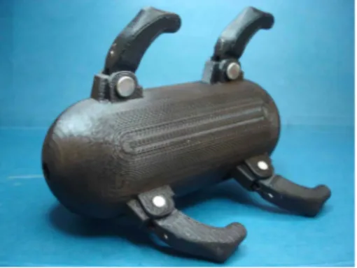
The prototype that we built for our preliminary experiments is shown in Fig. 4.
Size Limitations
The main challenge in the design of the mobility module is the fact that this module will host all other instrumentation and equipment, while at the same time it needs to be as small as possible in order to satisfy all space limitations within a very constrained pipe environment. The simplest limitation that one could think of is that the system’s diameter or width should be no more than the pipe’s ID, which in this case is 100mm. However the sizing of the module depends not only on the pipe ID but also on the pipe geometry.
Let’s now assume that the mobility module has a cylindrical shape with diameter H and length L. Consider the case when the module tries to pass a 90obend of an angle 2θ as the case shown 2011 by ASME
FIGURE 4. Our first prototype. ABS plastic along with a 3D printer was used for prototyping.
Ri Ro
L
H
θ
φFIGURE 5. A 2D sketch of a cylindrical mobility module inside a bended pipe.
in Fig. 5. The projection of the body in the plane will look like a rectangle with dimensions H and L.
If Ri and Rorepresent the inner and outer diameters of the
bend then by trigonometry we can get:
L= 2Rosinφ
or simply calculate the enclosed angle:
φ(L) = asin(L/2Ro) (1)
The following equation also holds:
Hmax(L) = Rocosφ(L)− Ri (2)
Eq. (1,2) can be used to calculate the angle φ and the maxi-mum height H given the length L as well as the pipe dimensions,
0 50 100 150 75 80 85 90 95 100 105 L Length of Module in [mm] H Thickness of Module in [mm]
L vs H for a module inside 90deg bend
FIGURE 6. Curve giving the maximum allowed thickness Hmax of the mobility module for a given length L..
namely Riand Ro. Most water pipes use Ri< 0.5D, while at the
same time we can write: Ro= Ri+ D . As an example we present
here the case where: Ri= 25mm and Ro= 125mm, which is in
general the most standard case for 100mm pipes. Fig. 6 shows the curve of the maximum allowable Hmax(L) over L for the given
pipe dimensions. Intuitevely, if the dimensions of our system are below the curve, the system will never jam in such a bended sec-tion. Such a section represents the worst case scenario for the movement of a floating body in a contrained environment, such as a water distribution pipe network.
As indicated in Fig. 1 the module’s length is 125mm. Eq. (1,2) imply that the diameter should be less than 85mm in order for the system to be able to fit in such bends and also T-junctions. Our prototype’s diameter is less than that; it is also not of exact cylindrical shape since we avoided the sharp edges in our design.
Degrees of Freedom
The position and orientation of a body in 3D space can be described by six coordinates. We can chose the following coordi-nates to fully describe the orientation and position of the system inside a pipeline: x y z φ(roll) θ (pitch) ψ (yaw)
Fig. 7 shows the DoF of the system within a pipe. In or-der for the system to be able to travel along the z-axis smoothly, some DoF need to be constrained. Those are x, y, θ and ψ. The 5 Copyright c 2011 by ASME
x
y
θ
z
ψφ
x
y
ψθ
FIGURE 7. The design of the mobility module. [Left] Front view. [Right] Side view.
constraint of the φ coordinate is not considered crucial at this point. Of course there is no constraint set on the z coordinate.
To summarize one can see that the current design and place-ment of the stabilizing legs offer the required constraints to the x, y, θ and ψ coordinates. Thus, the system is always placed in the middle of the pipe section and travels smoothly along the z direction collinearly to the longitudinal axis of the pipe.
Motion Analysis
The legs attached to the module can be used for control-ling its speed but also for “anchoring” the module in place, i.e. forcing the module’s speed to go to zero (Vm→ 0). This is
ex-tremely important when the system needs to have some more time to “sense” (or listen) to a leak or even if the system needs to transmit a large package of data to the receiver above ground. In this case “anchoring” may be the best option.
If the body is floating passively with speed Vm in a pipe
where water is flowing in the same direction with speed Vw, then
the relationship Vm≤ Vw holds, as shown in Fig. 8. By
control-ling the position of the legs, e.g. via step motors, it is possible to control Vmand also force Vm→ 0, if needed.
V
mV
wFIGURE 8. Body is floating within the pipe with speed Vm, while water speed is Vw.
By using a reference frame that is moving with the body, the mobility module seems to be stationary, water seems to flow with the relative speed Vrel= Vw−Vmand pipe seems to be moving to
the left with a speed of Vm, see Fig. 9. This analysis is used for
force calculations and later for flow (CFD) simulations. The total drag force can be computed from:
FD= 0.5CDρ AVrel2 (3)
V
mV
mV
w− V
mFIGURE 9. Body can be considered to be stationary in this case and water is flowing at a lower speed, namely Vrel= Vw−Vm. Notice that in this frame of reference the pipe wall is also moving with Vm.
where Vrel = Vw−Vm is the relative velocity, CDthe drag
coef-ficient of the module, A the reference area and ρ the density of water.
To withstand this force and control its speed, the module it-self is applying another force, on the opposite direction, by using the 6 legs utilizing friction. Let this force be Flegs.
A force balance on the body will give:
m ˙Vm= 0.5CDρ AVrel2 − Flegs
which leads to the equation of motion:
m ˙Vm= 0.5KVm2− KVwVm+ 0.5KVw2− Flegs (4)
where: K= CDρ A is a constant. Notice that m represents the
mass of the mobility module.
Eq. (4) is a nonlinear differential equation of Vm. We can
consider the force Flegsas the “input” to the differential equation, or else the ”forcing term”. Typical responses of the system are shown in Fig. 10 for different values of Flegs. One should
no-tice from the response that by applying a different friction force with the legs the system is able to “control” its steady state speed efficiently.
Flow Considerations in Design
As mentioned before, the mobility module is to be deployed in the pipe and will travel with the flow. A floating body inside the pipe network can be considered as an invasive method for leak detection. Nevertheless, the current design has been selected to minimize the change in the flow pattern and pressure distribu-tion. This is of great significance, since the sensor needs to be able to capture the unaffected leak signal without disturbing the flow and superimposing any interference to the leak signal. Not to mention that the sensing element is a very sensitive dynamic pressure transducer sensing very low amplitude acoustic signals. To study the flow pattern around the body inside a 100mm pipe various computational fluid dynamic simulations have been performed with the ANSYS CFD package (FLUENT). Steady 2011 by ASME
1N
2N
3N
0.5N
0 0.5 1 1.5 2 2.5 3 3.5 4 4.5 5 0 0.1 0.2 0.3 0.4 0.5 0.6 0.7 0.8 0.9 1 time [s] Velocity V m [m/s]FIGURE 10. The response of the system’s velocity for the following values: Vw= 1m/s, m = 1kg, CD= 0.4, A = 0.0165m2, ρ= 998kg/m3 and the initial condition is: Vm(0) = 0m/s. The response is presented for different values of Flegsvarying from 0.5 to 3N. Notice that by applying larger friction forces through the legs, the module travels with smaller speeds and can even “anchor” itself (Vm= 0).
state 3D turbulent flow simulations have been used to study the flow field, the pressure distribution around the body, velocity vectors and the calculation of drag coefficient. The standard k-e model is used for turbulence and the inlet velocity and pressure outlet boundary conditions are applied. Only the flow around the external hull is simulated excluding the legs and sensor nose. This was done intentionally for simplicity since small effect of the legs and sensor nose is expected due to their small size and smooth design. We used the simpler version of the main body to overcome some computational complexity, without at the same time losing significant information or changing dramatically the results of the simulation. Some characteristics of the mesh are presented in Table 1.
TABLE 1. Mesh characteristics
Number of Elements 1.018.974 Number of Nodes 186.118 Maximum Skewness Factor 0.81 Average Skewness Factor 0.22 Length of Pipe 2m Diameter of Pipe 100mm
It is considered that the maximum possible relative speed is 2m/s which corresponds to a stationary body and flowing water
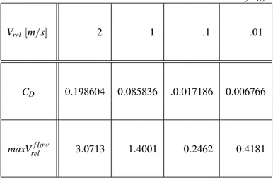
TABLE 2. CFD Results for different values of relative velocity Vrel.
Vrel[m/s] 2 1 .1 .01
CD 0.198604 0.085836 .0.017186 0.006766
maxVrelf low 3.0713 1.4001 0.2462 0.4181
at 2m/s, as discussed in the functional requirements. This will be the case if we force the body to stop (anchor) inside the pipe with average water velocity of 2 m/s. In normal situations, the body should flow (swim) with a speed which is very close to the water speed and the relative velocity will be negligible in this case. Nevertheless, we will study this “worst case scenario” in depth in the following paragraphs.
The line pressure is set constant to 200 kPa for all simu-lations. The “pressure” boundary condition was applied to the outlet section of the model. The relative velocity Vrel was
ap-plied at the inlet section, while we modeled the pipe walls as moving walls with speed Vm, as implied by Fig. 9. The “no-slip”
boundary condition was applied on the body’s walls.
Some of the results of the CFD simulations are summa-rized in Table 2 for a wide range of relative velocities between the floating body and water in pipe. As expected, the case for Vw= Vrel= 2 m/s while the body is not moving (Vm= 0) can be
considered as the worst scenario due to high viscous and pressure drag on the body.
The velocity vectors around the body are shown in Fig. 11 for a relative velocity Vrel= 2 m/s. The current streamlined de-sign of the body results in no flow separation at the body sur-face indicating that no induced turbulence from the body itself is expected. As expected, the maximum velocity occurs in the clearance between the body and the pipe material.
The pressure distribution around the body is shown in Fig.12 for a relative velocity Vrel= 2 m/s. There is a significant amount
of pressure variations in this case. In Fig. 13 the same pressure distribution is shown but this time for a relative velocity of Vrel=
0.01 m/s (body is floating with a speed of Vm= 1.99 m/s which
is very close to the water speed Vw= 2 m/s). It is clear that in
the latter simulation the pressure is almost constant around the body and this is due to the very small magnitude of the relative velocity Vrel.
Comparing the two figures but mostly focusing on Fig.12 , 7 Copyright c 2011 by ASME
FIGURE 11. CFD results for velocity vectors around the floating body. Simulation was done under Vrel = 2 m/s (direction from right to left) and P= 200kPa. No flow separation on the trailing edge.
FIGURE 12. CFD results for static pressure distribution around the floating body. Simulation was done under Vrel= 2 m/s (direction from right to left) and P= 200kPa. Placing the sensor nose at the trailing edge is the optimal solution.
it is clear that attaching the sensor to the body in the clearance between the body and the pipe is not correct due to the high gra-dient in pressure in this region. The only feasible location is the trailing edge of the body where the flow region is not disturbed ahead due to the existence of the body. The length of this undis-turbed flow region ahead of the body diminishes as the relative velocity goes to zero. This means that a sensor nose of 3 or 4cm (as shown in Fig. 2) will be suitable for detecting leak signals in the pipe ahead of the sensor.
Since the placement of the sensor has been now justified, placing well designed legs in the clearance between the body and the pipe is expected not to affect the flow in the trailing side of the body, where the sensor is located.
FIGURE 13. CFD results for static pressure distribution around the floating body. Simulation was done under Vrel= 0.01 m/s (direction from right to left (see Fig. 9) and P= 200kPa. Almost no pressure variation around the body.
FIGURE 14. The mobility module prototype inside a 100mm pipe section. The module is stable due to the support provided by the legs.
EXPERIMENTAL RESULTS
For the experimental evaluation we used the experimental setup located in our lab consisting of 100mm ID pipes as well as connections, T-junctions and bended sections (more details can be found here [17]). The pump provided the required high flow rates needed for the mobility module to be able to float inside the loop. The module was tested to evaluate stability and floating inside complicated pipeline configurations.
Stability
To evaluate stability we used a small pipe section with a size of 100mm. The prototype was placed inside a straight pipe section and stability was tested (Fig. 14). As expected, the six contact points from the legs provide the required stability to the module and at the same time they constraint the necessary DoF that were discussed in the corresponding section in this paper. In addition, the module is free to move along the z−axis of the pipe. 2011 by ASME
[a] [b]
[c] [d]
[e] [ f ]
FIGURE 15. The mobility module floating through the right branch of section C of the experimental setup. The six photos ([a]-[f]) show the motion of the mobility module from right to left. The module is within the red circle.
Floating
To evaluate how the module was able to float inside a “real” water distribution network we used the experimental setup along with the pump. The module was able to float without any prob-lem inside the water loop, being able to traverse bends and over-come T-junctions. For demonstration we will show here how the module performed in section “C”; namely the most difficult part of the loop. The module traverses the path in section “C” again by turning in the bends and overcoming any other obstacles with-out any problems. At the end of this section the module is being trapped by a net and removed from another T-junction. Fig. 15 and Fig. 16 show the floating of the module in this test section.
CONCLUSIONS AND FUTURE WORKS Conclusions
In this paper the design of an autonomous untethered free-floating leak detection system has been discussed. The designer
[ f ]
[g]
[h]
FIGURE 16. The mobility module floating through the left branch of section C of the experimental setup. The three photos ([f]-[h]) show the motion of the mobility module from right to left. The module is within the red circle.
of such a system has to take size limitations, flow field charac-teristics, functional and dexterity/maneuverability requirements into consideration. CFD simulations can be of a great help in siz-ing the module and decidsiz-ing on the sensor placement. A novel in-pipe floating platform has been designed, prototyped and tested in this work.
Future Works
Our future endeavors include the materialization of the whole miniaturized data acquisition system within a single body and deployment in a real network for inspection. The most chal-lenging task is going to be the incorporation of all modules in the same mobility module, namely sensing, data processing and communication. Localization techniques of the system inside the network along with communication with stations above ground are areas that we are currently working on.
ACKNOWLEDGMENT
The authors would like to thank the King Fahd University of Petroleum and Minerals for funding the research reported in this paper through the Center for Clean Water and Clean Energy at MIT and KFUPM. The authors would also like to thank Prof. Sanjay Sarma and his group for his valuable help in the construc-tion of the experimental setup.
Last but not least, the first author would like to thank the Onassis Public Benefit Foundation for the award of a prestigious scholarship throughout this work.
REFERENCES
[1] Vickers A. L. , 1999. “The future of water conservation: Challenges ahead”. Water Resources Update, Universities Council on Water Resources, 114, pp. 49–51.
[2] National Water Research Institute - Meteorological Service of Canada, 2004. “Threats to water availability in Canada”. Environment Canada. NWRI Scientific Assessment Report Series No. 3 and ACSD Science Assessment Series No. 1. [3] Al-Dhowalia K. H., Shammas N. Kh., Quraishi A. A. and
Al-Muttair F. F., 1989. “Assessment of leakage in the Riyadh water distribution network”. First Progress Report, King Abdulaziz City for Science and Technology.
[4] Mays L., 2000. Water Distribution Systems Handbook. McGraw-Hill.
[5] Hunaidi O., Chu W., Wang A. and Guan W., 1999. “Leak detection method for plastic water distribution pipes”. Ad-vancing the Science of Water, Fort Lauderdale Technol-ogy Transfer Conference, AWWA Research Foundation, pp. 249–270.
[6] Fuchs H. V. and Riehle R., 1991. “Ten years of experience with leak detection by acoustic signal analysis”. Applied Acoustics, 33, pp. 1–19.
[7] Hunaidi O. and Chu W., 1999. “Acoustical characteristics of leak signals in plastic water distribution pipes”. Applied Acoustics, 58, pp. 235–254.
[8] Bracken M. and Hunaidi O., 2005. “Practical aspects of acoustical leak location on plastic and large diameter pipe”. Leakage 2005 Conference Proceedings(448-452).
[9] Kurtz D. W., 2006. “Developments in a free-swimming acoustic leak detection system for water transmission pipelines”. ASCE Conf. Proc., 25(211).
[10] Bond A., Mergelas B. and Jones C., 2004. “Pinpointing leaks in water transmission mains”. ASCE Conf. Proc., 91(146).
[11] Schempf H., Mutschler E., Goltsberg V., Skoptsov G., Gavaert A. and Vradis G., 2003. “Explorer: Untethered real-time gas main assessment robot system”. Proc. of Int. Workshop on Advances in Service Robotics (ASER). [12] Kwon Y-S., Jung E-J., Lim H. and Yi B-J., 2007.
“De-sign of a reconfigurable indoors pipeline inspection robot”.
International Conference on Control, Automation and Sys-tems, pp. 3998–4004.
[13] Choi H-R. and Roh S-G, 2005. “Differential-drive in-pipe robot for moving inside urban gas pipelines”. Transactions on Robotics, 21(1).
[14] Hunaidi O., Chu W., Wang A. and Guan W., 2000. “De-tecting leaks in plastic pipes”. Journal - American Water Works Association, 92(2), pp. 82–94.
[15] Hunaidi O., Wang A., Bracken M., Gambino T. and Fricke C., 2004. “Acoustic methods for locating leaks in municipal water pipe networks”. International Conference on Water Demand Management, pp. 1–14.
[16] Khalifa A., Chatzigeorgiou D., Youcef-Toumi K., Khulief Y. and Ben-Mansour R., 2010. “Quantifying acoustic and pressure sensing for in-pipe leak detection”. ASME Inter-national Mechanical Engineering Congress & Exposition (IMECE2010).
[17] Chatzigeorgiou D., 2010. “Analysis and design of an in-pipe system for water leak detection”. Master’s thesis, De-partment of Mechanical Engineering, Massachusetts Insti-tute of Technology, Cambridge, MA, USA.
[18] Chatzigeorgiou D., Khalifa A., Youcef-Toumi K. and Ben-Mansour R., 2011. “An in-pipe leak detection sensor: Sens-ing capabilities and evaluation”. ASME/IEEE International Conference on Mechatronic and Embedded Systems and Applications (MESA2011).
[19] Chatzigeorgiou D., Kumar S., Khalifa A., Deshpande A., Youcef-Toumi K., Sarma S. and Ben-Mansour R., 2010. “In-pipe acoustic characterization of leak signals for leak detection in water distribution networks”. AWWA Annual Conference and Exposition.