Publisher’s version / Version de l'éditeur:
Vous avez des questions? Nous pouvons vous aider. Pour communiquer directement avec un auteur, consultez la première page de la revue dans laquelle son article a été publié afin de trouver ses coordonnées. Si vous n’arrivez pas à les repérer, communiquez avec nous à [email protected].
Questions? Contact the NRC Publications Archive team at
[email protected]. If you wish to email the authors directly, please see the first page of the publication for their contact information.
https://publications-cnrc.canada.ca/fra/droits
L’accès à ce site Web et l’utilisation de son contenu sont assujettis aux conditions présentées dans le site LISEZ CES CONDITIONS ATTENTIVEMENT AVANT D’UTILISER CE SITE WEB.
Client Report (National Research Council of Canada. Construction); no.
A1-000030.02, 2014-03-17
READ THESE TERMS AND CONDITIONS CAREFULLY BEFORE USING THIS WEBSITE.
https://nrc-publications.canada.ca/eng/copyright
NRC Publications Archive Record / Notice des Archives des publications du CNRC :
https://nrc-publications.canada.ca/eng/view/object/?id=c3721a34-56a4-452b-9427-6065cb1d91f0 https://publications-cnrc.canada.ca/fra/voir/objet/?id=c3721a34-56a4-452b-9427-6065cb1d91f0
NRC Publications Archive
Archives des publications du CNRC
For the publisher’s version, please access the DOI link below./ Pour consulter la version de l’éditeur, utilisez le lien DOI ci-dessous.
https://doi.org/10.4224/23002851
Access and use of this website and the material on it are subject to the Terms and Conditions set forth at
Performance evaluation of proprietary drainage components and
sheathing membranes when subjected to climate loads, task 2:
building component hygrothermal properties characterization
Mukhopadhyaya, Phalguni; Van Reenen, David; Bundalo-Perc, Sladana
Performance Evaluation of Proprietary
Drainage Components and Sheathing
Membranes when Subjected to Climate Loads
Task 2 — Building Component Hygrothermal
Properties Characterization
Phalguni Mukhopadhyaya, David van Reenen and
Sladana Bundalo-Perc
Table of Contents
Table of Contents i
List of Figures iii
List of Tables v
Acknowledgements vii
Summary ix
1. Introduction
1
2. Hygrothermal Properties Determination
4
2.1 Drainable SBPO Sheathing Membrane (Client A) 4 2.2 Water Repellent Insulation Board (Client B) 6 2.3 Open matrix Nylon mesh bonded to nonwoven sheathing membrane (Client C) 9 2.4 Cross woven, micro-perforated polyolefin sheathing membrane (Client D) 11 2.5 HDPE dimpled membrane bonded to PP4fabric (Client E) 13
2.5 Non-woven PP fabric bonded to PP mono-filament mesh (Client G) 15 2.7 Porous PS insulation board (Client H) 17 2.8 Corrugated asphalt impregnated paper board (Client I) 20 2.9 Three Coat Stucco with Expanded Diamond-Mesh Metal Lath (Client J) 23
3
Air flow Characterization of Drainage Components
26
3.1 Test Method 26
3.2 Drainage Systems Tested 26
3.3 Test Results 27
3.3.1 Test Number 1 - Empty Ventilation Cavity (Reference wall) 27
3.3.2 Test Number 2 - Open matrix Nylon mesh (7mm) (Client C) 28
3.3.3 Test Number 3 – Nylon mesh bonded to PP non-woven sheathing membrane (Client C) 30
3.3.4 Test Number 4 – Non-woven PP fabric bonded to PP mono-filament mesh (Client G) 31
3.3.5 Test Number 5 – PP fabric bonded to dimpled HDPE membrane (Client E) 32
3.3.6 Test Number 6 – Corrugated asphalt impregnated paper board (Client I) 34
4. References
35
Appendix 1 List of Project Reports 37
List of Figures
Figure 1 – SBPO Sheathing Membrane... 4
Figure 2 – Water Repellent Insulation Board ... 6
Figure 3 – Open matrix Nylon mesh bonded to nonwoven sheathing membrane... 9
Figure 4 – Drainage Building Wrap ... 11
Figure 5 – HDPE dimpled membrane bonded to PP fabric ... 13
Figure 6 – Non-woven PP fabric bonded to PP mono-filament mesh... 15
Figure 7 – Porous PS insulation board ... 17
Figure 8 – Corrugated asphalt impregnated paper board... 20
Figure 9 – Three coat stucco with expanded diamond-mesh metal lath... 23
Figure 10 – Test Setup for Air Flow Characterization of Drainage Components ... 26
Figure 11 – Permeability as a function of specimen height ... 28
Figure 12 – Open matrix Nylon mesh (Client C)... 28
Figure 13 – Permeability as a function of specimen height (Client C)... 29
Figure 14 – Nylon mesh bonded to PP non-woven sheathing membrane (Client C) ... 30
Figure 15 – Permeability as a function of specimen height (Client C)... 31
Figure 16 – Non-woven PP fabric (stucco screen) bonded to PP mono-filament mesh (Client G) ... 31
Figure 17 – Permeability as a function of specimen height (Client G) ... 32
Figure 18 – PP fabric bonded to dimpled HDPE membrane (Client E) ... 32
Figure 19 – Permeability as a function of specimen height (Client E)... 33
Figure 20 – Corrugated asphalt impregnated paper board (Client I)... 34
Figure 21 – Permeability as a function of specimen height (Client I) ... 35
Figure A 1 – Reference Wall Cross-Section... 39
Figure A 2 – Client A Wall Cross-Section ... 39
Figure A 3 – Client B Wall Cross-Section... 40
Figure A 4 – Client C Wall Cross-Section... 40
Figure A 5 – Client D Wall Cross-Section ... 41
Figure A 6 – Client E Wall Cross-Section... 41
Figure A 7 – Client F Wall Cross-Section ... 42
Figure A 8 – Client G Wall Cross-Section ... 42
Figure A 9 – Client H Wall Cross-Section ... 43
Figure A 10 – Client I Wall Cross-Section... 43
List of Tables
Table 1 – List of wall assemblies for which hygrothermal properties were sought ... 2
Table 2 – List of drainage layers for which air flow was characterized ... 3
Table 4 – Sorption Characteristic of SBPO Sheathing Membrane... 4
Table 5 – Water Vapour Permeability of SBPO Sheathing Membrane... 5
Table 6 – Thermal Conductivity of Water Repellent Insulation Board... 6
Table 7 – Sorption Characteristic of Water Repellent Insulation Board ... 7
Table 8 – Water Vapour Permeability of Water Repellent Insulation Board ... 7
Table 9 – Thermal Conductivity - Open Nylon mesh bonded to nonwoven sheathing membrane... 9
Table 10 – Water Vapour Permeability of open matrix Nylon mesh bonded to nonwoven sheathing membrane ... 10
Table 11 – Water Vapour Permeability of cross woven, micro-perforated polyolefin sheathing membrane ... 12
Table 12 – Thermal Conductivity of HDPE dimpled membrane bonded to PP fabric... 13
Table 13 – Water Vapour Permeability of HDPE dimpled membrane bonded to PP fabric ... 14
Table 14 – Thermal Conductivity of non-woven PP fabric bonded to PP mono-filament mesh ... 15
Table 15 – Water Vapour Permeability of non-woven PP fabric bonded to PP mono-filament mesh... 16
Table 16 – Thermal Conductivity of Porous PS insulation board... 17
Table 17 – Sorption characteristic of Porous PS insulation board ... 18
Table 18 – Water Vapour Permeability of Porous PS insulation board ... 18
Table 19 – Sorption Characteristic of corrugated asphalt impregnated paper board... 20
Table 20 – Water Vapour Permeability of corrugated asphalt impregnated paper board... 21
Table 21 – Water Absorption Coefficient of corrugated asphalt impregnated paper board ... 21
Table 22 – Thermal Conductivity of 3 coat stucco with expanded diamond-mesh metal lath ... 23
Table 23 – Sorption characteristic of Three Coat Stucco ... 24
Table 24 – Water Vapour Permeability of Three Coat Stucco... 24
Table 25 – Water Absorption Characteristics of Three Coat Stucco... 25
Table 26 – Tested Ventilation Components... 27
Table 27 – Air Permeability and Permeance of Clear (empty) Cavity ... 27
Table 28 – Air Permeability and Permeance of Open matrix Nylon mesh... 29
Table 29 – Air Permeability & Permeance of Nylon mesh bonded to PP non-woven sheathing membrane ... 30
Table 30 – Air Permeability & Permeance of Non-woven PP fabric bonded to PP mono-filament mesh. 32 Table 31 – Air Permeability and Permeance of PP fabric bonded to dimpled HDPE membrane... 33
Acknowledgements
The report authors wish to extend their thanks to the Air Barrier Association of American (ABAA) for having managed and arranged support for this project and in particular, to Mr. Laverne Dalgleish for his highly proficient handling of all technical and non-technical issues that arose over the course of the project. As well, acknowledgment is made of project support, technical meeting participation and the many and very useful contributions made by the respective project partners, and that included:
Benjamin Obdyke Incorporated
Canadian Concrete Masonry Producers Association Cosella-Dorken
DuPont Tyvek Weatherization Systems HAL Industries Incorporated
Home Protection Office of British Columbia – HPO Keene Building Products™
GreenGuard® Building Products (formerly Pactiv Building Products) Roxul Incorporated
STO Corporation
TYPAR® Weather Protection System (Polymer Group Incorporated)
Our thanks are also extended to our colleagues within NRC-Construction for their technical support, advice, and feedback during the course of this project and who helped support the work described in this Task report including: M. Armstrong, S. M. Cornick, B. Di Lenardo, G. Ganapathy, W. Maref, T. Moore, M. Nicholls, H. H. Saber, and M.C. Swinton.
Summary
A benchmark assembly and a series of ten client wall assemblies were developed as part of the project “Performance Evaluation of Proprietary Drainage Components and Sheathing Membranes when Subjected to Climate Loads”.
The purpose of this project was to assess the performance of wall drainage components and sheathing membranes (drainage system) in their ability to provide sufficient drainage and drying in Canadian climates with a moisture index (MI) greater than 0.9 and less than 3400 degree-days, or MI greater than 1.0 and degree days ≥ 3400 (primarily coastal areas). In these regions, the 2010 National Building Code requires a capillary break behind all Part 9 claddings. Currently, acceptable solutions to the NBC capillary break requirement include:
(a) A drained and vented air space not less than 10 mm deep behind the cladding;
(b) An open drainage material, not less than 10 mm thick and with a cross-sectional area that is not less than 80% open, behind the cladding;
(c) A cladding loosely fastened, with an open cross section (i.e. vinyl, aluminum siding)
(d) A masonry cavity wall or masonry veneer constructed according to Section 9.20 (i.e. 25 mm vented air space)
In this project, the performance of proposed alternative solutions for the capillary break was compared through laboratory evaluation and modeling activities to the performance of a wall built to minimum code requirements. The proposed drainage system would be deemed an alternative solution to the capillary break requirement in the National Building Code for use with all code compliant Part 9 claddings provided it exhibits adequate moisture performance as compared to a NBC-compliant benchmark wall assembly.
In This Report — A set of reliable and representative hygrothermal property data were generated of a number of selected building materials, including all drainage components and sheathing membranes, for hygrothermal simulation of wall assemblies.
In addition to regular measurements, additional tests were conducted to quantify the air flow performance of several drainage components used in the drainage cavities of the client recommended wall assemblies.
Performance Evaluation of Proprietary Drainage Components and
Sheathing Membranes when Subjected to Climate Loads –
Task 2 – Building Component Hygrothermal Properties
Characterization
Authored by:
Phalguni Mukhopadhyaya, David van Reenen and Sladana Bundalo-Perc
A Report for the
AIR BARRIER ASSOCIATION OF AMERICA
National Research Council Canada Ottawa ON K1A 0R6 Canada
March 17, 2014
This report may not be reproduced in whole or in part without the written consent of both the client and the National Research Council of Canada.
Performance Evaluation of Proprietary Drainage Components and
Sheathing Membranes when Subjected to Climate Loads –
Task 2 – Building Component Hygrothermal Properties
Characterization
Final Report Task 2
Phalguni Mukhopadhyaya, David van Reenen and Sladana Bundalo-Perc
1. Introduction
In this project, the hygrothermal performance of proposed solutions for wall assemblies incorporating drainage components was compared through laboratory evaluation and modeling activities to the performance of a NBC1-compliant wall built to minimum code requirements. The hygrothermal
properties and air flow characteristics were determined to quantify the hygrothermal performance of different wall assemblies. The wall assemblies consisted of a reference wall system and the respective wall assemblies of interest to the project clients, each assembly having a different method for drainage of the wall cavity; a list of these walls is provided in Table 1 and horizontal sectional details are given in Appendix 2.
To carry out hygrothermal performance assessments of wall assemblies using the numerical simulation tool hygIRC-C, the hygrothermal properties of all materials used for the construction of the different wall assemblies was required. Many of the hygrothermal properties of materials of the respective wall assemblies are available in NRC’s material properties database. For several materials, however, appropriate hygrothermal properties were not available and tests to determine hygrothermal properties of these materials were completed as part of this project. Accordingly, the hygrothermal properties have been determined for the materials listed in Table 1 and in which the designated wall section in which they were used is also given. The results of the testing, together with the methods used to determine the respective hygrothermal properties, are provided in §2 of this report and in the order provided in Table 1 starting with Client A.
In addition, to permit quantifying the drying potential of various drainage layers, the air flow characteristics along the height of a wall of the respective drainage components were also examined using the method to determine the air permeability of materials, as described in §2, and according to the procedure given by Bomberg and Kumaran (1986). The drainage configurations tested are given in Table 2 and the results and test methods used in the testing for air flow characteristics of these products are provided in §3 of this report.
It should also be noted that the air flow characteristics of clear cavities (i.e. 10, 20 and 25 mm) as well as cavities incorporating drainage components (i.e. Clients C, G, E and I) were characterized using another apparatus, a description of which is given, and for which results are provided, in the Task 4 report2.
1NBC- National Building Code Canada 2010 2A list of project reports is provided in Appendix 1
TASK 2 — BUILDING COMPONENT HYGROTHERMAL PROPERTIES CHARACTERIZATION
REPORT A1-000030.02 2
Table 1 – List of wall assemblies for which hygrothermal properties were sought
Designations Description of Drainage Component
Description of component tested for
hygrothermal properties
Reference wall Air space created by 19 mm plywood strapping; on NBC Code-compliant building paper* NBC Code-compliant stucco Client A Wall
Code compliant building paper* / cap fasteners provide 2 mm gap / Drainable SBPO** sheathing membrane
Drainable SBPO sheathing membrane
Client B Wall 10 mm air space / Water repellent insulation board (76 mm) / liquid applied membrane Water repellent insulation board Client C Wall
Code compliant building paper*/ Nylon mesh (10 mm; open matrix) / PP†nonwoven sheathing membrane
Nylon mesh (10 mm; open matrix) bonded to PP nonwoven sheathing membrane
Client D Wall
Code compliant building paper*/ Cap fasteners provide 2 mm gap / Cross woven, micro-perforated polyolefin sheathing membrane with polyolefin coating
Cross woven, micro-perforated polyolefin sheathing membrane with polyolefin coating
Client E Wall PP†fabric (stucco screen) / Dimpled HDPE‡ (11 mm) membrane / Code compliant building paper*
PP†fabric bonded to dimpled HDPE‡ membrane
Client F Wall Stucco-clad wall having 25 mm air space / Code
compliant building paper* Nil (25 mm air space) Client G Wall Non-woven PP
†fabric (stucco screen) / PP†mat
(10 mm; 3-dimensional extruded PP mono-filament mesh) / Code compliant building paper*
Non-woven PP†fabric (stucco screen) / PP†mat (10 mm; PP mono-filament mesh)
Client H Wall Porous PS††insulation board (52 mm) / liquid applied membrane
Porous PS††insulation board (52 mm)
Client I Wall
2 ply, corrugated asphalt impregnated paper*; Grade D!!(4.2 mm) / Code-compliant building
paper*
2 ply, corrugated asphalt impregnated paper* - Grade D!!
Client J Wall
Building paper*; Grade D!!; 60 Minute /
Air space created by 9.5 mm plywood strapping / 2 layers of Code compliant building paper*
Three coat stucco with expanded diamond metal lath
Client K Wall
Building paper*, Grade D!!; 60 Minute /
Air space created by 9.5 mm plywood strapping / 2 layers of Code compliant building paper*
Three coat stucco with paper backed welded wire metal lath
* Conforming to CGSB standard CAN2-51.32-M77; ** SBPO – Spun bonded polyolefin; † PP - polypropylene; ‡
HDPE – high density polyethylene; †† PS – polystyrene; !! Conforming to US Federal Specification UU-B-790a
Table 2 – List of drainage layers for which air flow was characterized3
Description of drainage layer Designations
Clear (empty) cavity (7mm) Reference wall Open matrix Nylon mesh; alone (7mm) Client C Wall Nylon mesh (10 mm; open matrix) bonded to PP†nonwoven sheathing
membrane Client C Wall
Non-woven PP†fabric (stucco screen) bonded to PP†mono-filament
mesh providing a 10 mm mat Client G Wall PP†fabric bonded to dimpled HDPE‡ membrane Client E Wall 2 ply, corrugated asphalt impregnated paper* - Grade D!! Client I Wall
† PP - polypropylene;‡HDPE – high density polyethylene; * Conforming to CGSB standard
CAN2-51.32-M77; !! Conforming to US Federal Specification UU-B-790a (Type I - Barrier paper; Grade D Water-vapor permeable; Style 2 - Uncreped, not reinforced, saturated)
3The air flow characteristics of clear cavities (i.e. 10, 20 and 25 mm) as well as cavities incorporating drainage
components (i.e. Clients C, G, E and I) were also characterized using another apparatus, a description of which is given, and for which results are provided, in the Task 4 report (see Appendix 1).
TASK 2 — BUILDING COMPONENT HYGROTHERMAL PROPERTIES CHARACTERIZATION
REPORT A1-000030.02 4
2. Hygrothermal Properties Determination
2.1
Drainable SBPO Sheathing Membrane (Client A)
The test specimens used for the various measurements presented in this report were taken from SBPO membranes (Figure 1) having a nominal membrane thickness of 0.16mm. The thickness of the membrane, when crinkled, was 0.62 mm. The properties shown below are calculated with the nominal membrane thickness.
Figure 1 – SBPO Sheathing Membrane
Density: 560 kg m-3
Heat Capacity: 1250 J K-1kg-1 (Kumaran, et al. 2002)
Thermal Conductivity:
Thermal conductivity measurements were not conducted due to practical limitations of the test method for this material.
Sorption Measurements:
The measurements were done following the procedure described in ASTM Standard C1498 (ASTM International, 2010). The results from these tests are shown in Table 3.
Table 3 – Sorption Characteristic of SBPO Sheathing Membrane
Relative Humidity (% RH) Moisture Content(kg•kg-1) 50.0 0.00035 70.8 0.00024 90.3 0.00019 94.3 0.00123
Water Vapour Permeability:
Water vapour permeability testing was conducted following the procedure given in ASTM Standard E96/96M (ASTM International 2010). The procedure specified in this standard for calculating the dependence of water vapour transmission rate on relative humidity was used to determine the water vapour permeability of the SBPO sheathing membrane. For each test condition, a minimum of 3 circular specimens of 150 mm diameter were tested.
As shown in Table 4, the water vapour permeability had a constant value of 4.41×10⁻¹³kg m-1s-1Pa-1.
Table 4 – Water Vapour Permeability of SBPO Sheathing Membrane
Relative Humidity (%) Water Vapour Permeability (kg m-1s-1Pa-1) Relative Humidity (%) Water Vapour Permeability (kg m-1s-1Pa-1) 10 4.41×10⁻¹³ 60 4.41×10⁻¹³ 20 4.41×10⁻¹³ 70 4.41×10⁻¹³ 30 4.41×10⁻¹³ 80 4.41×10⁻¹³ 40 4.41×10⁻¹³ 90 4.41×10⁻¹³ 50 4.41×10⁻¹³ 100 4.41×10⁻¹³
Water Absorption Coefficient:
The value for the water absorption coefficient of the SBPO sheathing membrane is very low and is not measureable.
Air Permeability:
The measurements and calculations were conducted according to the procedure reported by Bomberg and Kumaran (1986). Three circular test specimens, with the same dimensions as the specimens used to determine the water vapour permeability of the SBPO sheathing membrane were used for measurements of air permeability. Measurements were conducted at a temperature of 22 ± 1 ° C.
The resulting air permeability was:
TASK 2 — BUILDING COMPONENT HYGROTHERMAL PROPERTIES CHARACTERIZATION
REPORT A1-000030.02 6
2.2
Water Repellent Insulation Board (Client B)
The test specimens (Figure 2) used for the various measurements presented in this report were taken from insulation boards having a nominal thickness of 70 mm. The water repellent insulation board was made with mineral fibre insulation.
Figure 2 – Water Repellent Insulation Board
Density: 75.3 kg m-3
Heat Capacity: 840 J K-1kg-1 (Kumaran, et al. 2002)
Thermal Conductivity:
Measurements were conducted in accordance with ASTM Standard C518 (ASTM International 2010). The specimens were tested in an apparatus with a nominal 600 mm x 600 mm cross section. Heat flow was perpendicular to this primary surface. Also note that, for materials tested in the heat flow apparatus used to conduct the tests, the measurement uncertainties are within 2%. The measured thermal conductivity values are shown in Table 5.
Table 5 – Thermal Conductivity of Water Repellent Insulation Board
Specimen Thickness (mm) Hot Surface Temperature (°C) Cold surface Temperature (°C) Conductivity (W m-1K-1) 69.93 35.08 13.08 0.035 69.75 35.00 13.00 0.035 69.42 34.99 13.00 0.035
Sorption Isotherm:
Six specimens with nominal size of 51 mm x 51 mm x 50 mm were used in these measurements. The tests were done following the procedure described in ASTM Standard C1498 (ASTM International, 2010). The results from these tests are shown in Table 6.
Table 6 – Sorption Characteristic of Water Repellent Insulation Board
Relative Humidity (% RH) Moisture content(kg•kg-1) 50.3 0.0011 69.3 0.0014 88.7 0.0022 94.2 0.0099
Water Vapour Permeability:
Water vapour permeability testing was conducted following the procedure in ASTM Standard E96/96M (ASTM International 2010). The procedure specified in this standard for calculating the dependence of water vapour transmission rate on relative humidity was used to determine the water vapour permeability of the water repellent insulation board. For each test condition, a minimum of 3 circular specimens of 150 mm diameter (Figure 1) were tested.
As shown below (Table 7), the water vapour permeability had a constant value of 1.47×10⁻¹⁰kg m-1s-1Pa-1.
Table 7 – Water Vapour Permeability of Water Repellent Insulation Board
Relative Humidity (%) Water Vapour Permeability (kg m-1s-1Pa-1) Relative Humidity (%) Water Vapour Permeability (kg m-1s-1Pa-1) 10 1.47×10⁻¹⁰ 60 1.47×10⁻¹⁰ 20 1.47×10⁻¹⁰ 70 1.47×10⁻¹⁰ 30 1.47×10⁻¹⁰ 80 1.47×10⁻¹⁰ 40 1.47×10⁻¹⁰ 90 1.47×10⁻¹⁰ 50 1.47×10⁻¹⁰ 100 1.47×10⁻¹⁰
TASK 2 — BUILDING COMPONENT HYGROTHERMAL PROPERTIES CHARACTERIZATION
REPORT A1-000030.02 8
Water Absorption Coefficient:
The value for the water absorption coefficient of the water repellent insulation board is very low and is not measureable.
Air Permeability:
The measurements and calculations were conducted according to the procedure reported by Bomberg and Kumaran (1986). Three circular test specimens, of the same dimensions as specimens used for the water vapour permeability tests were used for the air permeability measurements. Measurements were conducted at a temperature of 22 ± 1 ° C.
The resulting air permeability was:
2.3
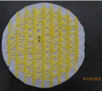
Open matrix Nylon mesh bonded to nonwoven sheathing membrane
(Client C)
The test specimens used for the various measurements presented in this report were taken from samples of Open matrix Nylon mesh bonded to nonwoven sheathing membrane (Figure 3) having a nominal thickness of 10 mm. The measured thickness was 10.5 mm.
Figure 3 – Open matrix Nylon mesh bonded to nonwoven sheathing membrane
Density: 43.5 kg m-3
Heat Capacity: 1210 J K-1kg-1 (Kumaran, et al. 2002)
Thermal Conductivity:
The thermal conductivity of the open matrix Nylon mesh bonded to nonwoven sheathing membrane was determined in accordance with ASTM Standard C518 (ASTM International 2010). The specimen enclosed in a wood-frame was tested in an apparatus with a nominal cross section of 300 mm x 300 mm. Heat flow was perpendicular to this primary surface. Also note that, for materials tested in the heat flow apparatus used to conduct the reported tests, the measurement uncertainties are within 2%. The measured thermal conductivity value is shown in Table 8.
Table 8 – Thermal Conductivity - Open Nylon mesh bonded to nonwoven sheathing membrane
Specimen Thickness (mm) Hot Surface Temperature (°C) Cold surface Temperature (°C) Conductivity (W m-1K-1) 10.69 35.0 13.0 0.065
TASK 2 — BUILDING COMPONENT HYGROTHERMAL PROPERTIES CHARACTERIZATION
REPORT A1-000030.02 10
Water Vapour Permeability:
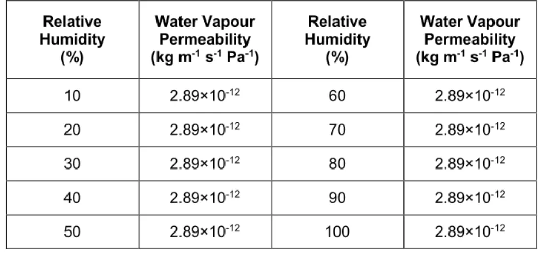
Water vapour permeability testing was conducted following the procedure in ASTM Standard E96/96M (ASTM International 2010). The procedure specified in this standard for calculating the dependence of water vapour transmission rate on relative humidity was used to determine the water vapour permeability of the open matrix Nylon mesh bonded to nonwoven sheathing membrane. For each test condition, a minimum of 3 circular specimens, having a 150 mm diameter, were tested. Results are shown in Table 9.
Table 9 – Water Vapour Permeability of Open matrix Nylon mesh bonded to nonwoven sheathing membrane
Relative Humidity (%) Water Vapour Permeability (kg m-1s-1Pa-1) Relative Humidity (%) Water Vapour Permeability (kg m-1s-1Pa-1) 10 2.89×10⁻¹² 60 2.89×10⁻¹² 20 2.89×10⁻¹² 70 2.89×10⁻¹² 30 2.89×10⁻¹² 80 2.89×10⁻¹² 40 2.89×10⁻¹² 90 2.89×10⁻¹² 50 2.89×10⁻¹² 100 2.89×10⁻¹²
Water Absorption Coefficient:
The water absorption coefficient of the open matrix Nylon mesh bonded to nonwoven sheathing membrane is very low and is not measureable.
Air Permeability:
The measurements and calculations to determine the air permeability of the open matrix Nylon mesh bonded to nonwoven sheathing membrane were carried out as described in §3. Average permeability values derived from tests undertaken at different heights were determined and from which:
The resulting air permeability was determined as: 9.4×10³L(75 Pa)-1·m-1·s-1
The air permeability for air flow perpendicular to the mesh was also measured; the resulting air permeability was:
2.4 Cross woven, micro-perforated polyolefin sheathing membrane (Client D)
The test specimens for the cross woven, micro-perforated polyolefin sheathing membrane (Figure 4) used for the various measurements had a nominal thickness of 0.76 mm.
Figure 4 – Drainage Building Wrap
Density: 167.5 kg m-3
Heat Capacity: 1250 J K-1kg-1(Kumaran, et al. 2002)
Thermal Conductivity:
Thermal measurements were not conducted due to practical limitations of conducting the test on this material.
Sorption Isotherm:
The sorption capacity of this material was extremely low and not measureable. Water Vapour Permeability:
Water vapour permeability testing was conducted following the procedure given in ASTM Standard E96/96M (ASTM International 2010). The procedure specified in this standard for calculating the dependence of water vapour transmission rate on relative humidity was used to determine the water vapour permeability of the cross woven, micro-perforated polyolefin sheathing membrane. For each test condition, a minimum of 3 circular specimens having a 150 mm diameter were tested.
As shown in Table 10, the water vapour permeability had a constant value of 5.80×10⁻¹³kg m-1s-1Pa-1.
TASK 2 — BUILDING COMPONENT HYGROTHERMAL PROPERTIES CHARACTERIZATION
REPORT A1-000030.02 12
Table 10 – Water Vapour Permeability of the cross woven, micro-perforated polyolefin sheathing membrane
Relative Humidity (%) Water Vapour Permeability (kg m-1s-1Pa-1) Relative Humidity (%) Water Vapour Permeability (kg m-1s-1Pa-1) 10 5.80×10⁻¹³ 60 5.80×10⁻¹³ 20 5.80×10⁻¹³ 70 5.80×10⁻¹³ 30 5.80×10⁻¹³ 80 5.80×10⁻¹³ 40 5.80×10⁻¹³ 90 5.80×10⁻¹³ 50 5.80×10⁻¹³ 100 5.80×10⁻¹³
Water Absorption Coefficient:
The water absorption coefficient of the cross woven, micro-perforated polyolefin sheathing membrane is very low and is not measureable.
Air Permeability:
The air permeability measurements and calculations were conducted according to the procedure reported by Bomberg and Kumaran (1986). Three circular test specimens, with the same dimensions as specimens used to determine the water vapour permeability were used for measurements of air permeability. Measurements were conducted at a temperature of 22 ± 1 ° C. The resulting value for the air permeability of the cross woven, micro-perforated polyolefin sheathing membrane was:
2.5
HDPE
4dimpled membrane bonded to PP
4fabric (Client E)
The test specimens of the HDPE dimpled membrane bonded to PP fabric used for the various measurements presented in this report were taken from samples having a nominal thickness of 10 mm (Figure 5). The measured thickness was 10.6 mm. Note that this measurement is representative of the overall thickness comprised of the HDPE dimpled membrane and the PP fabric.
Figure 5 – HDPE dimpled membrane bonded to PP fabric
Density: 59.4 kg m-3
Heat Capacity: 1210 J K-1kg-1 (Kumaran, et al. 2002)
Thermal Conductivity:
The thermal conductivity of the HDPE dimpled membrane bonded to PP fabric was determined in accordance with ASTM Standard C518 (ASTM International 2010). The specimen enclosed in a wood-frame was tested in an apparatus with a nominal cross section of 300 mm x 300 mm. Heat flow was perpendicular to this primary surface. Also note that, for materials tested in the heat flow apparatus used to conduct the tests for thermal conductivity, the measurement uncertainties are within 2%. The measured thermal conductivity value is shown in Table 11.
Table 11 – Thermal Conductivity of HDPE dimpled membrane bonded to PP fabric
Specimen Thickness (mm) Hot Surface Temperature (°C) Cold surface Temperature (°C) Conductivity (W m-1K-1) 10.63 35.2 13.0 0.048
The average thermal conductivity was 0.048 W m-1K-1tested with a mean temperature of 24.1 °C
TASK 2 — BUILDING COMPONENT HYGROTHERMAL PROPERTIES CHARACTERIZATION
REPORT A1-000030.02 14
Water Vapour Permeability:
Water vapour permeability testing was conducted following the procedure in ASTM Standard E96/96M (ASTM International 2010). The procedure specified in this standard for calculating the dependence of water vapour transmission rate on relative humidity was used to determine the water vapour permeability of the HDPE dimpled membrane bonded to PP fabric. For each test condition, a minimum of 3 circular specimens, having a 150 mm diameter, were tested. Results are shown in the Table 12.
Table 12 – Water Vapour Permeability of HDPE dimpled membrane bonded to PP fabric
Relative Humidity (%) Water Vapour Permeability (kg m-1s-1Pa-1) Relative Humidity (%) Water Vapour Permeability (kg m-1s-1Pa-1) 10 2.56×10⁻¹³ 60 2.56×10⁻¹³ 20 2.56×10⁻¹³ 70 2.56×10⁻¹³ 30 2.56×10⁻¹³ 80 2.56×10⁻¹³ 40 2.56×10⁻¹³ 90 2.56×10⁻¹³ 50 2.56×10⁻¹³ 100 2.56×10⁻¹³
Water Absorption Coefficient:
The water absorption coefficient of the HDPE dimpled membrane bonded to PP fabric is very low and is not measureable.
Air Permeability:
The measurements and calculations were carried out as described in the §3. The average permeability values of various channel heights of the HDPE dimpled membrane bonded to PP fabric were determined and the resulting air permeability was:
5.92×10³L(75 Pa)-1·m-1·s-1
The air permeability for air flow perpendicular to the HDPE dimpled membrane was also measured and was found impermeable.
2.5
Non-woven PP
5fabric bonded to PP mono-filament mesh (Client G)
The test specimens of non-woven PP fabric bonded to PP mono-filament mesh and used for the various measurements presented in this report were taken from samples with a nominal thickness of 10 mm (Figure 6). The measured thickness was 9.3 mm.
Figure 6 – Non-woven PP fabric bonded to PP mono-filament mesh
Density: 48.7 kg m-3
Heat Capacity: 1210 J K-1kg-1 (Kumaran, et al. 2002)
Thermal Conductivity:
The thermal conductivity of the non-woven PP fabric bonded to a PP mono-filament mesh was determined in accordance with ASTM Standard C518 (ASTM International 2010). The specimen enclosed in a wood-frame was tested in an apparatus with a nominal cross section of 300 mm x 300 mm. Heat flow was perpendicular to this primary surface. Also note that, for materials tested in the heat flow apparatus used to conduct tests of thermal conductivity, the measurement uncertainties are within 2%. The measured thermal conductivity value is shown in Table 13.
Table 13 – Thermal Conductivity of non-woven PP fabric bonded to PP mono-filament mesh Specimen Thickness (mm) Hot Surface Temperature (°C) Cold surface Temperature (°C) Conductivity (W m-1K-1) 9.37 35.0 13.0 0.060
The average thermal conductivity was 0.060 W m-1K-1tested with a mean temperature of 24.0 °C
5PP - polypropylene
TASK 2 — BUILDING COMPONENT HYGROTHERMAL PROPERTIES CHARACTERIZATION
REPORT A1-000030.02 16
Water Vapour Permeability:
Water vapour permeability testing was conducted following the procedure in ASTM Standard E96/96M (ASTM International 2010). The procedure specified in this standard for calculating the dependence of water vapour transmission rate on the relative humidity was used to determine the water vapour permeability of the non-woven PP fabric bonded to PP mono-filament mesh. For each test condition, a minimum of 3 circular specimens, having a diameter of 150 mm, were tested. Results are shown in Table 14.
Table 14 – Water Vapour Permeability of non-woven PP fabric bonded to PP mono-filament mesh Relative Humidity (%) Water Vapour Permeability (kg m-1s-1Pa-1) Relative Humidity (%) Water Vapour Permeability (kg m-1s-1Pa-1) 10 1.21×10⁻¹⁰ 60 1.21×10⁻¹⁰ 20 1.21×10⁻¹⁰ 70 1.21×10⁻¹⁰ 30 1.21×10⁻¹⁰ 80 1.21×10⁻¹⁰ 40 1.21×10⁻¹⁰ 90 1.21×10⁻¹⁰ 50 1.21×10⁻¹⁰ 100 1.21×10⁻¹⁰
Water Absorption Coefficient:
The water absorption coefficient of the non-woven PP fabric bonded to PP mono-filament mesh is very low and is not measureable.
Air Permeability:
The measurements and calculations were carried out as described in the §3. The average permeability values of various channel heights were determined and the resulting air permeability was determined to be:
4.7×10³L(75 Pa)-1·m-1·s-1
The air permeability for air flow perpendicular to the mesh was also measured. The resulting air permeability was:
2.7
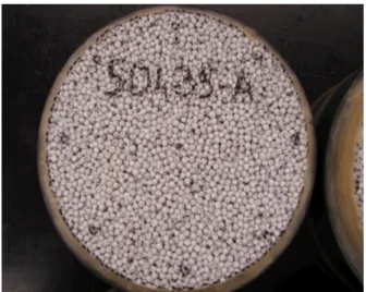
Porous PS
6insulation board (Client H)
The test specimens (Figure 7) of porous PS insulation board used for the various measurements presented in this report were taken from insulation boards with a nominal thickness of 51 mm.
Figure 7 – Porous PS insulation board
Density: 29.2 kg m-3
Heat Capacity: 1470 J K-1kg-1(Kumaran, et al. 2002)
Thermal Conductivity:
Measurements were conducted in accordance with ASTM Standard C518 (ASTM International 2010). The specimens were tested in an apparatus with a 600 mm x 600 mm cross section. Heat flow was perpendicular to this primary surface. Also note that, for materials tested in the heat flow apparatus used to conduct the tests, the measurement uncertainties are within 2%. The measured thermal conductivity values are shown in Table 15.
Table 15 – Thermal Conductivity of Porous PS insulation board
Specimen Thickness (mm) Hot Surface Temperature (°C) Cold surface Temperature (°C) Conductivity (W m-1K-1) 51.64 34.95 13.03 0.039 51.23 34.97 13.03 0.039 51.34 35.03 12.97 0.038
The average thermal conductivity was 0.038 W m-1K-1tested with a mean temperature of 24.0 °C.
6PS – polystyrene
TASK 2 — BUILDING COMPONENT HYGROTHERMAL PROPERTIES CHARACTERIZATION
REPORT A1-000030.02 18
Sorption Measurements:
Six specimens with a nominal size of 50 mm x 50 mm x 100 mm were used in these measurements. The measurements were done following the procedure described in ASTM Standard C1498 (ASTM International, 2010). The results from these tests are shown in Table 16.
Table 16 – Sorption characteristic of Porous PS insulation board
Relative Humidity (% RH) Moisture Content(kg•kg-1) 50.3 0.0057 69.3 0.0092 90.5 0.0259 94.2 0.0677
Derived Water Vapour Permeability:
Water vapour permeability testing was conducted following the procedure given in ASTM Standard E96/96M (ASTM International 2010). The procedure specified in this standard for calculating the dependence of water vapour transmission rate on relative humidity was used to determine the water vapour permeability of the Porous PS insulation board. For each test condition, a minimum of 3 circular specimens of 150 mm diameter (Figure 7) were tested.
As shown in Table 17, the derived water vapour permeability had a constant value of 3.56×10⁻¹¹kg m-1s-1Pa-1.
Table 17 – Water Vapour Permeability of Porous PS insulation board
Relative Humidity (%) Water Vapour Permeability (kg m-1s-1Pa-1) Relative Humidity (%) Water Vapour Permeability (kg m-1s-1Pa-1) 10 3.56×10⁻¹¹ 60 3.56×10⁻¹¹ 20 3.56×10⁻¹¹ 70 3.56×10⁻¹¹ 30 3.56×10⁻¹¹ 80 3.56×10⁻¹¹ 40 3.56×10⁻¹¹ 90 3.56×10⁻¹¹ 50 3.56×10⁻¹¹ 100 3.56×10⁻¹¹
Water Absorption Coefficient:
The value for the water absorption coefficient of the porous PS insulation board is very low and was not measureable.
Air Permeability:
The measurements and calculations were conducted according to the procedure reported by Bomberg and Kumaran (1986). Three circular test specimens, with the same dimensions as the specimens used to test for water vapour permeability were used for the measurements of air permeability. Measurements were executed at a temperature of 22 ± 1 ° C. The resulting air permeability was:
TASK 2 — BUILDING COMPONENT HYGROTHERMAL PROPERTIES CHARACTERIZATION
REPORT A1-000030.02 20
2.8
Corrugated asphalt impregnated paper board (Client I)
The test specimens of 2-ply corrugated asphalt impregnated paper board (Figure 8) used for the various measurements presented in this report were taken from samples having a nominal thickness 3.77 mm.
Figure 8 – Corrugated asphalt impregnated paper board
Density: 147.5 kg m3
Heat Capacity: 1250 J K-1kg-1 (Kumaran, et al. 2002)
Thermal Conductivity:
Thermal measurements were not conducted given practical limitations in completing the test. Sorption Measurements:
The measurements to determine the sorption of the corrugated asphalt impregnated paper board were done following the procedure described in ASTM Standard C1498 (ASTM International, 2010). Five specimens were used in these measurements. The results of the testing are shown in Table 18.
Table 18 – Sorption Characteristic of corrugated asphalt impregnated paper board
Relative Humidity (% RH) Moisture Content(kg•kg-1) 49.9 0.028 71.0 0.0493 90.5 0.122 94.4 0.210
Water Vapour Permeability:
Water vapour permeability testing was conducted following the procedure in ASTM Standard E96/96M (ASTM International 2010). The procedure specified in this standard for calculating the dependence of water vapour transmission rate on relative humidity was used to determine the water vapour permeability
of the corrugated asphalt impregnated paper board. For each test condition, a minimum of 3 circular specimens, having a diameter of 150 mm, were tested. The results of the water vapour testing are shown in Table 19.
Table 19 – Water Vapour Permeability of corrugated asphalt impregnated paper board
Relative Humidity (%) Water Vapour Permeability (kg m-1s-1Pa-1) Relative Humidity (%) Water Vapour Permeability (kg m-1s-1Pa-1) 10 4.98×10⁻¹³ 60 3.35×10⁻¹² 20 7.22×10⁻¹³ 70 5.06×10⁻¹² 30 1.05×10⁻¹² 80 7.83×10⁻¹² 40 1.53×10⁻¹² 90 1.26×10⁻¹¹ 50 2.26×10⁻¹² 100 2.20×10⁻¹¹ Water Absorption Coefficient:
Five test specimens, each having dimensions of 50 mm × 50 mm × 50 mm, were used for measurements to determine the water absorption coefficient of the corrugated asphalt impregnated paper board. Water was maintained at 22 ± 1 °C during the test period. The values for water absorption are given in Table 20. The numbers in parentheses give the standard deviations of the resulting values for water absorption as a function of time.
Table 20 – Water Absorption Coefficient of corrugated asphalt impregnated paper board
Square Root of time
(s½) Water Absorption(kg m-2) 24.5 0.109 (0.005) 34.6 0.118 (0.010) 42.4 0.123 (0.007) 60.0 0.138 (0.007) 73.5 0.146 (0.009) 84.9 0.158 (0.009) 103.9 0.173 (0.012) 120.0 0.186 (0.008) 148.0 0.222 (0.006) 169.7 0.242 (0.011) 201.2 0.272 (0.008) 295.5 0.376 (0.010) 311.8 0.393 (0.018)
TASK 2 — BUILDING COMPONENT HYGROTHERMAL PROPERTIES CHARACTERIZATION
REPORT A1-000030.02 22
Linear regression using all the data from the first linear part of the absorption process for the five specimens derives the water absorption coefficient for the corrugated asphalt impregnated paper board which was determined to be 0.0010 kg m-2s-½.
Air Permeability:
The measurements and calculations were carried out as described in §3. The average permeability values of various channel heights were determined and the resulting air permeability was:
1.75×10³L(75 Pa)-1·m-1·s-1
The air permeability for air flow perpendicular to the paper board was also measured. The resulting air permeability was:
2.9
Three Coat Stucco with Expanded Diamond-Mesh Metal Lath (Client J)
The test specimens of three coat stucco with expanded diamond-mesh metal lath (Figure 9) used for the various measurements presented in this report were constructed at the NRC. The specimens that were tested had a nominal thickness of 26.4 mm.
Figure 9 – Three coat stucco with expanded diamond-mesh metal lath
Density: 1890 kg m-3
Heat Capacity: 840 J K-1kg-1(Kumaran, et al. 2002)
Thermal Conductivity:
Measurements were conducted in accordance with ASTM Standard C518 (ASTM International 2010). The specimens were tested in an apparatus with a 300 mm x 300 mm cross section. Heat flow was perpendicular to this primary surface. Also note that, for materials tested in the heat flow apparatus that was used to conduct the tests, the measurement uncertainties were within 2%. The measured thermal conductivity value is shown in Table 21.
Table 21 – Thermal Conductivity of 3 coat stucco with expanded diamond-mesh metal lath
Specimen Thickness (mm) Hot Surface Temperature (°C) Cold surface Temperature (°C) Conductivity (W m-1K-1) 29.28 27.2 18.4 0.71
The average thermal conductivity of the three coat stucco was 0.71 W m-1K-1tested with a mean
TASK 2 — BUILDING COMPONENT HYGROTHERMAL PROPERTIES CHARACTERIZATION
REPORT A1-000030.02 24
Sorption Isotherm:
Five specimens of size 250 mm x 250 mm x 27 mm were tested to determine the sorption isotherm of the three coat stucco. The measurements were done following the procedure described in ASTM Standard C1498 (ASTM International, 2010). The results from these tests are shown in Table 22.
Table 22 – Sorption characteristic of Three Coat Stucco
Relative Humidity (% RH) Moisture content (kg•kg-1) 50.3 0.025 69.3 0.028 89.9 0.048 93.9 0.059
Water Vapour Permeability:
Water vapour permeability testing was conducted following the procedure given in ASTM Standard E96/96M (ASTM International 2010). The procedure specified in this standard for calculating the dependence of water vapour transmission rate on relative humidity was used. For each test condition, a minimum of 3 circular specimens, having a diameter of 150 mm, were tested. The results from these tests are shown in Table 23.
Table 23 – Water Vapour Permeability of Three Coat Stucco
Relative Humidity (%) Water Vapour Permeability (kg m-1s-1Pa-1) Relative Humidity (%) Water Vapour Permeability (kg m-1s-1Pa-1) 10 2.06×10⁻¹² 60 4.28×10⁻¹² 20 2.50×10⁻¹² 70 4.73×10⁻¹² 30 2.94×10⁻¹² 80 5.18×10⁻¹² 40 3.39×10⁻¹² 90 5.64×10⁻¹² 50 3.83×10⁻¹² 100 6.09×10⁻¹²
Water Absorption Coefficient:
Ten test specimens, each having dimensions of 50 mm x 50 mm x 50 mm, were used to determine the water absorption coefficient of the three coat stucco. Over the course of the test, water was maintained at (22 ± 1) °C. The results (average) from these measurements are shown in Table 24. The numbers in parentheses give the standard deviations.
Table 24 – Water Absorption Characteristics of Three Coat Stucco
Square Root of Time
(s½) Water Absorption(kg m-2) 24.5 0.38 (0.12) 34.6 0.55 (0.16) 42.4 0.69 (0.20) 60.0 1.01 (0.26) 84.9 1.38 (0.31) 103.9 1.61 (0.33) 120.0 1.75 (0.34) 169.7 2.02 (0.37) 199.0 2.11 (0.37) 293.9 2.25 (0.37) 317.5 2.26 (0.37) 339.4 2.27 (0.37) 417.1 2.29 (0.37) 432.0 2.28 (0.37) 449.3 2.28 (0.37)
Linear regression using all the data from the first linear part of the absorption process for the ten specimens gives the value of the water absorption coefficient; this value was 0.0157 kg m-2s-½.
Air Permeability:
The measurements and calculations for air permeability of the three coat stucco were executed according to the procedure reported by Bomberg and Kumaran (1986). Three circular test specimens, with the same dimensions as specimens used for the water vapour permeability tests were used for the measurements of air permeability. Measurements were executed at a temperature of 22 ± 1 ° C.
The resulting air permeability was:
TASK 2 — BUILDING COMPONENT HYGROTHERMAL PROPERTIES CHARACTERIZATION
REPORT A1-000030.02 26
3 Air flow Characterization of Drainage Components
The objective of this portion of the study was to quantify the air flow characteristics of the ventilation systems used in the various wall sections. The air permeability values derived
from these tests would be used for simulations of vertical airflow through the drainage plane.
3.1
Test Method
The specimens were tested according to the same procedure used for all of the air permeability testing conducted as described in the report by (Kumaran and Bomberg 1986). In order to quantify the air flow in the drainage channels and to examine the effects of the height of the channel on experimental results, four channel heights were tested; these were: 14.3 cm; 28.5 cm; 42.8 cm; and 57.0 cm. The air permeability of the ventilation components was tested using the test configuration shown in Figure 10 and includes photos of the test set-up for the smallest (14.3 cm) and greatest (57 cm) heights tested.
3.2
Drainage Systems Tested
The air flow characteristics of six different drainage system ventilation components were examined as provided in Table 25. The tests were conducted on specimens with varying height as specified in the previous section. Several of the ventilation matting materials also had different cross sections in directions parallel and perpendicular to the channel flow. For these meshes, tests were conducted in two directions. The tests that were conducted are shown in Table 25. Results from these tests are provided in the subsequent section.
Figure 10 – Test Setup for Air Flow Characterization of Drainage Components
57.0 cm height
14.3 cm height
Table 25 – Tested Ventilation Components
Test
No. Description Parallel Flow (Y) Perpendicular Flow (X)
1 Clear (empty) cavity (7mm) X N/A
2 Open matrix Nylon mesh; alone (7mm) X X 3 Nylon mesh (10 mm; open matrix) bonded to PP†
nonwoven sheathing membrane X X
4 Non-woven PP†fabric (stucco screen) bonded to PP†
mono-filament mesh providing a 10 mm mat X N/A 5 PP†fabric bonded to dimpled HDPE‡ membrane X X 6 2 ply, corrugated asphalt impregnated paper* - Grade D!! X X
† PP - polypropylene; ‡ HDPE – high density polyethylene; * Conforming to CGSB standard
CAN2-51.32-M77; !! Conforming to US Federal Specification UU-B-790a (Type I - Barrier paper; Grade D Water-vapor permeable; Style 2 - Uncreped, not reinforced, saturated)
3.3
Test Results
3.3.1 Test Number 1 – Clear (empty) Cavity (Reference wall)
The values of permeability and permeance of the board in the Y-direction are provided in Table 26; as well, values of permeability and permeance of the board for different board heights (X- and Y-direction) are likewise given. In Figure 11 values of permeability are plotted as a function of test height.
The results suggest that the values for permeability in the Y-direction did vary significantly with test height; average permeability in the Y- direction was ca. 2.09E+04 L/m•s @75 Pa with a variance of 0.585 E+03 L/m•s @75 Pa or ca. 30%.
This variability is more evident in Figure 11 and perhaps suggests that the highest value is an outlier. Table 26 – Air Permeability and Permeance of Clear (empty) Cavity
Specimen Heightm L·(75 Pa)Permeability-1·m-1·s-1 L·(75 Pa)Permeance-1·m-2·s-1
459-115 0.143 1.576E+04 1.106E+05 459-113 0.285 2.236E+04 7.844E+04 459-119 0.428 2.985E+04 6.974E+04 459-117 0.570 1.557E+04 2.732E+04
TASK 2 — BUILDING COMPONENT HYGROTHERMAL PROPERTIES CHARACTERIZATION
REPORT A1-000030.02 28
Figure 11 – Permeability as a function of specimen height
3.3.2 Test Number 2 - Open matrix Nylon mesh (7mm) (Client C)
A photo of the open matrix Nylon mesh is given in Figure 12. The values of permeability and permeance of the component in the X, Y, and Z-directions are provided in Table 27; as well, values of permeability and permeance of the component for different heights (X- and Y-direction) are likewise given. In Figure 13 values of permeability are plotted as a
function of test height.
The results suggest that the values for permeability in either the X- or Y-directions did not significantly vary with test height; average permeability in the X- direction was ca. 1.8E+03 L/m•s @75 Pa and in the Y-direction was ca. 4.3E+03 L/m•s @75 Pa. The permeability in the Z-direction was not measurable although in this instance it did not offer any measurable resistance to flow.
Figure 12 – Open matrix Nylon mesh (Client C)
0.0E+00 5.0E+03 1.0E+04 1.5E+04 2.0E+04 2.5E+04 3.0E+04 3.5E+04 0.00 0.10 0.20 0.30 0.40 0.50 0.60 Pe rm ea bi lit y, l· (7 5 Pa ) -1·m -1·s -1 Height, m
Effect of Specimen Size on Permeability
X Y
Table 27 – Air Permeability and Permeance of Open matrix Nylon mesh
Flow
Direction Heightm l·(75 Pa)Permeability-1·m-1·s-1 l·(75 Pa)Permeance-1·m-2·s-1 Y-direction 0.143 3.235E+03 2.270E+04
0.285 4.018E+03 1.410E+04 0.428 5.134E+03 1.200E+04 0.570 4.690E+03 8.228E+03 X-direction 0.143 1.517E+03 1.056E+04 0.285 1.885E+03 6.614E+03 0.428 2.033E+03 4.751E+03 0.570 1.785E+03 3.132E+03
Z-direction NA NA NA
Figure 13 – Permeability as a function of specimen height (Client C)
0.0E+00 5.0E+03 1.0E+04 1.5E+04 2.0E+04 2.5E+04 3.0E+04 3.5E+04 0.00 0.10 0.20 0.30 0.40 0.50 0.60 Pe rm ea bi lit y, l· (7 5 Pa ) -1·m -1·s -1 Height, m
Effect of Specimen Size on Permeability
Y-Direction X-DirectionTASK 2 — BUILDING COMPONENT HYGROTHERMAL PROPERTIES CHARACTERIZATION
REPORT A1-000030.02 30
3.3.3 Test Number 3 – Nylon mesh bonded to PP non-woven sheathing membrane
(Client C)
A photo of the Nylon mesh bonded to a PP non-woven sheathing membrane is given in Figure 14. The values of permeability and permeance of the component in the X, Y, and Z-directions are provided in Table 28; as well, values of permeability and permeance of the component for different heights (X- and Y-direction) are likewise given. In Figure 15 values of
permeability are plotted as a function of test height. The results suggest that the values for permeability in either the X- or Y-directions did not significantly vary with test height; average permeability in the X- direction was ca. 4.1E+03 L/m•s @75 Pa and in the Y-direction was ca. 9.5E+03 L/m•s @75 Pa.
The permeability in the Y-direction (7.5E-03L/m•s @75 Pa) was 6 orders of magnitude less than that of the permeability in the X- or Y-directions; it represents the permeability of the membrane to air.
Figure 14 –
Nylon mesh bonded to PP
non-woven sheathing membrane
(Client C) Table 28 – Air Permeability and Permeance of
Nylon mesh bonded to
PP non-woven sheathing membrane
Flow Direction
Height m
Permeability
L·(75 Pa)-1·m-1·s-1 L·(75 Pa)Permeance-1·m-2·s-1 Y-Direction 0.143 7.492E+03 5.239E+04
0.285 8.405E+03 2.949E+04 0.428 1.231E+04 2.875E+04 0.570 9.676E+03 1.698E+04 X-Direction 0.143 3.669E+03 2.565E+04 0.285 4.216E+03 1.479E+04 0.428 3.765E+03 8.796E+03 0.570 4.608E+03 8.085E+03 Z-Direction 0.011 7.489E-03 7.103E-01
X Y
Figure 15 – Permeability as a function of specimen height (Client C)
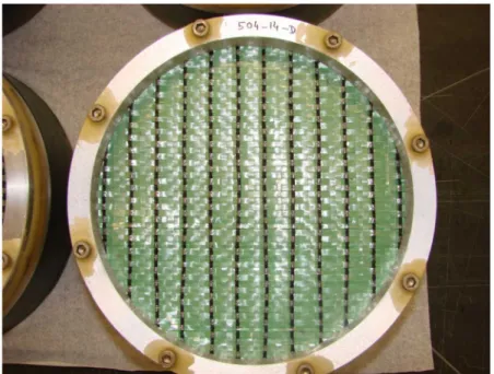
3.3.4 Test Number 4 – Non-woven PP fabric (stucco screen) bonded to PP mono-filament
mesh (Client G)
A photo of the Non-woven PP fabric (stucco screen) bonded to PP mono-filament mesh is given in Figure 16. The values of permeability and permeance of the component in the X, Y, and Z-directions are provided in Table 29; as well, values of permeability and permeance of the component for different heights (X- and Y-direction) are likewise given. In Figure 17 values of permeability are plotted as a function of test height.
The results suggest that the values for permeability of the component do not vary in the X- or Y-direction, and thus do not depend on the test height; average permeability in the X- (or Y-direction was
ca. 4.7E+03 L/m•s @75 Pa.
The permeability in the Y-direction (8.1E+01
L/m•s @75 Pa) was much less than that of the permeability in the X- or Y-directions, (ca. 2 orders of magnitude); it represents the permeability of the membrane to air.
Figure 16 – Non-woven PP fabric (stucco screen) bonded to PP mono-filament mesh (Client G)
1.0E-03 1.0E-02 1.0E-01 1.0E+00 1.0E+01 1.0E+02 1.0E+03 1.0E+04 1.0E+05 0.00 0.10 0.20 0.30 0.40 0.50 0.60 Pe rm ea bi lit y, l· (7 5 P a) -1·m -1·s -1 Height, m
Effect of Specimen Size on Permeability
Y-Direction X-Direction Z-Direction
X Y
TASK 2 — BUILDING COMPONENT HYGROTHERMAL PROPERTIES CHARACTERIZATION
REPORT A1-000030.02 32
Table 29 – Air Permeability and Permeance of Non-woven PP fabric (stucco screen) bonded to PP mono-filament mesh Flow Direction Height m Permeability
L·(75 Pa)-1·m-1·s-1 L·(75 Pa)Permeance-1·m-2·s-1 X and Y 0.143 3.611E+03 2.525E+04
0.285 3.532E+03 1.239E+04 0.428 6.251E+03 1.461E+04 0.570 5.286E+03 9.274E+03 Z 0.00940 8.069E+01 8.545E+03
Figure 17 – Permeability as a function of specimen height (Client G)
3.3.5 Test Number 5 – PP fabric bonded to dimpled HDPE membrane (Client E)
A photo of the PP fabric bonded to dimpled HDPE membrane is given in Figure 18. The values of permeability and permeance of the component in the X, Y, and Z-directions are provided in Table 30; as well, values of permeability and permeance of the component for different heights (Y-direction) are likewise given. In Figure 19 values of permeability are plotted as a function of test height. The results suggest that the values for permeability of the component do not vary in the X- or Y-direction, and thus do not depend on the test height; average permeability in the
X-direction was ca. 3.30E+03 L/m•s @75 Pa and in the Y-X-direction ca. 5.92E+03 L/m•s @75 Pa.
1.0E-03 1.0E-02 1.0E-01 1.0E+00 1.0E+01 1.0E+02 1.0E+03 1.0E+04 1.0E+05 0.00 0.10 0.20 0.30 0.40 0.50 0.60 Pe rm ea bi lit y, l· (7 5 P a) -1·m -1·s -1 Height, m
Effect of Specimen Size on Permeability
X & Y-Direction Z-Direction
Figure 18 –PP fabric bonded to dimpled HDPE membrane
(Client E) X Y
Permeability in the X-direction is slightly less than that in the Y-direction; i.e. 2.6E+03 L/m•s @75 Pa. Given that the permeability of the membrane in the Z-direction was not measurable it was deemed essentially impermeable to air.
Table 30 – Air Permeability and Permeance of PP fabric bonded to dimpled HDPE membrane
Flow
Direction Heightm L·(75 Pa)Permeability-1·m-1·s-1 L·(75 Pa)Permeance-1·m-2·s-1 Y-Direction 0.143 5.837E+03 4.082E+04
0.285 5.621E+03 1.972E+04 0.428 6.459E+03 1.509E+04 0.570 5.773E+03 1.013E+04 X-Direction 0.143 3.425E+03 2.395E+04 0.285 3.123E+03 1.096E+04 0.428 3.491E+03 8.156E+03 0.570 3.170E+03 5.562E+03 Z-Direction 0.011 Not measurable Not measurable
Figure 19 – Permeability as a function of specimen height (Client E)
1.0E-03 1.0E-02 1.0E-01 1.0E+00 1.0E+01 1.0E+02 1.0E+03 1.0E+04 1.0E+05 0.00 0.10 0.20 0.30 0.40 0.50 0.60 Pe rm ea bi lit y, l· (7 5 P a) -1·m -1·s -1 Height, m
Effect of Specimen Size on Permeability
TASK 2 — BUILDING COMPONENT HYGROTHERMAL PROPERTIES CHARACTERIZATION
REPORT A1-000030.02 34
3.3.6 Test Number 6 – Corrugated asphalt impregnated paper board (Client I)
A photo of the
corrugated asphalt impregnated paper board
is given in Figure 20. The values of permeability and permeance of the component in the X, Y, and Z-directions are provided in Table 31; as well, values of permeability and permeance of the component for different heights (Y-direction) are likewise given. These same values are plotted in Figure 21.The results suggest that the values for permeability of the component do not vary in the Y-direction, and thus do not depend on the test height; average permeability value in the Y-direction is
ca. 1.75E+03 L/m•s @75 Pa.
Permeability in the X-direction is ca. two (2) orders of magnitude less than that in the Y-direction and the least permeability is that in the
Z-direction (7.5E-03 L/m•s @75 Pa); this value represents the permeability of the membrane to air. Table 31 – Air Permeability and Permeance of
corrugated
asphalt impregnated paper board
Flow
Direction Height(m) l·(75 Pa)Permeability-1·m-1·s-1 l·(75 Pa)Permeance-1·m-2·s-1 Y-Direction 0.143 1.405E+03 9.823E+03
0.285 1.849E+03 6.489E+03 0.428 2.021E+03 4.721E+03 0.570 1.737E+03 3.047E+03 X-Direction 0.143 6.885E+01 4.815E+02 Z-Direction 0.011 7.489E-03 7.103E-01
Figure 20 – C
orrugated
asphalt impregnated
paper board
(Client I)X Y
Figure 21 – Permeability as a function of specimen height (Client I)
4. References
ASTM Standard C1498-04a "Standard Test Method for Hygroscopic Sorption Isotherms of Buidling Materialas". West Chonshocken, PA: ASTM International, 2004.
ASTM Standard C518-10 "Standard Test Method for Steady-State Thermal Transmission Properties by Means of the Heat Flow Meter Apparatus". West Conshohocken, PA, 2010.
ASTM Standard E96/E96M - 10 "Standard Test Method for Water Vapor Transmission of Materials".
West Conshohocken, PA: ASTM International, 2010.
Kumaran, M. K., and M. T. Bomberg (1986), "A Test Method to determine air flow resistane of exterior membranes and sheathings"." Journal of Thermal Insulation: 9: 224-235.
Kumaran, Mavinkal K, John K Lackey, Nicole Normandin, Fitsum Tariku, and David van Reenen (2002), "A Thermal and Moisture Transport Property Database for Common Building and Insulating Materials: Final Report"; ASHRAE Research Project 1018-RP.
1.0E-03 1.0E-02 1.0E-01 1.0E+00 1.0E+01 1.0E+02 1.0E+03 1.0E+04 1.0E+05 0.00 0.10 0.20 0.30 0.40 0.50 0.60 Pe rm ea bi lit y, l· (7 5 P a) -1·m -1·s -1 Height, m
Effect of Specimen Size on Permeability
TASK 2 — BUILDING COMPONENT HYGROTHERMAL PROPERTIES CHARACTERIZATION