OPTIMIZATION OF A MINIATURIZED ELECTROSPRAY DEVICE BY
COMBINING HIGH SPEED VIDEO IMAGING AND FEM MODELLING
Böhringer S
1, Kalle C
1, Hradetzky D
11
Insitute for Medical and Analytical Technologies, University of Applied Sciences and Arts
Northwestern Switzerland, Switzerland
[email protected]
Abstract: Gene therapeutic treatment of idiopathic
pulmo-nary fibrosis seems to be a promising approach. Delivery of plasmids into the alveolar epithelial cells avoiding transfec-tion viral and non-viral vectors based transfectransfec-tion may be realized using proposed electrospray method.
In order to obtain design rules for a miniaturized elec-trospray device for gene therapy, fitting within the working channel of a bronchoscope, we combined the image analysis of High Speed Videos with electrostatic simulation using Finite Element Method to characterize evolving electrospray modes depending on the electrical field distribution. Based on this approach we intend to predict the generated elec-trospray modes and behaviour depending on the particular design of the electrospray instrument.
Keywords: Electrospray, Drug delivery, Bronchoscope,
Gene delivery
Introduction
Gene therapy of idiopathic pulmonary fibrosis seems to be a suitable and promising approach [1]. The challenge is to deliver the genes to the affected regions enabling the transfection into the cells. One approach relies on the use of electrical fields to accelerate charged water droplets containing the plasmid and bombard the cells, so called electrospray [2].
To enable this kind of treatment in a clinical set up a device concept useable within a working channel of a bronchoscope providing the accelerating field with a single port access configuration is required. This repre-sents our approach for a new minimal invasive instru-ment.
Basically electrospray is a cloud of charged droplets or single droplets produced between two high voltage elec-trodes. One typical arrangement is based on a capillary, forming the first electrode and delivering the plasmid solution, and a second planar counter electrode. The elec-trical field between the electrodes, called the “working field”, leads to the formation of a Taylor Cone, a shape of the liquid formed at the tip of the capillary. Though the field force charge in form of little droplets is removed from the cone. These droplets are accelerated towards the counter electrode.
We expect that the electrical field strength at the tip of the capillary is mainly responsible for the droplet formation, while the shape of the electrical field lines dominates the direction stability of the process.
Methods
Unfortunately we are not able to observe the spray modes and behavior within a miniaturized device due to optical access limitations. Therefore we use an optimization approach as followed. For gathering information about the spray modes and the electrical field, we used first an experimental set up to analyze the modes using High Speed Imaging of the spray process, and calculated the electrical fields of given set up using finite Element Mod-eling tool (COMSOL Multiphysics). From this data we determine the dependency of electrical field distribution and droplet generation. Assuming a similar electrical field distribution in a miniaturized device we expect similar droplet generation behavior.
The simple experimental setup contains a capillary (i.200) to deliver the liquid, connected to High Voltage, and a target made of steel, acting as ground electrode. The working area was observed with a High Speed Imaging System (MotionPro Y3-S2 at 17500Hz sample rate) ap-plying a shadow imaging technique [3] and the videos were evaluated concerning droplet size, arrangement and speed using the video analysis tool ProAnalyst at certain applied voltages and with de-ionized water and a DNA- solution.
For the optimization of a miniaturized device design the electrical field distribution was simulated, including nec-essary electrical interconnects as an integrated ground electrode for single port access. Furthermore the influence of additional geometrical and electrical modifications was investigated, in order to obtain a distribution of the elec-trical field close to successfully operating experimental set ups.
Results
Three different modes of electrospray were observed within the high speed videos at 3 mm working distance. First, at voltages in the range of 2.3-2.75 kV, in the “Jet Spray Mode” a slim jet is emitted at the tip of the Taylor Cone. The jet molds in a smooth spray of droplets, being too small to be observed with the used camera system. The droplets spread away in a funnel like shape with an angle of until 40 degree. Second is the “Drop Jet Spray Mode”, consisting of a jet and a few droplets with a size of about 30-200 µm diameter. The jet collapses into drop-lets, forming a trajectory collinear to the jet axis. The necessary voltage is in the range of 2.75-3.75kV. Above 3.75kV, in the mode called “Drop Mode”, the jet disap-pears and the droplets are emitted directly out of the Tay-lor Cone. The droplet size is in the same range than in the
Drop Jet Spray Mode with a slight tendency to form larg-er droplets.
Investigating environmental parameters we observed several possibilities to influence of the electrospray in Drop Jet Spray and Drop Mode. Using the smaller capil-lary diameter in the Droplet Mode the droplets become smaller. Increasing the flow rate above 25µl/min leads to an almost linear grow of the droplet size, while flow rates above lead to a decrease of droplet release frequency at constant size.
In relation to the stability of the trajectory and the fact that the possibility of cell penetration is given with bigger droplets[4], the Drop modes are focused in further inves-tigations and the next steps.
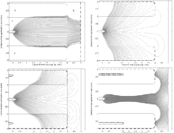
Figure 1: Shape of the electrical field in different electrical designs. The dashed lines indicates the ground surface, the dotted ones the shield surface. (a) is the device wall, (b) the
target tissue, (c) the chamber of the device
In a second step we compared the Influence of geometry and electrical interconnect of a real, miniaturized device to the experimental setup design. Figure 1 (top left) shows the electrical field lines of the experimental like setup (external connected ground electrode), compared to our first instrument design (top right) with an unshielded ground electrode at the outside housing and an improved designs (bottoms) with an additional shielding along the capillary (left) and along 40% of the device chamber length (right).
The electrical field lines of the first design diverge signif-icantly (Figure 1). As these lines correspond to the direc-tion of applied force on droplets, they will be accelerated more towards the housing than towards the target. There-fore this design leads to an unstable spray process. In order to obtain a stable process, a second electrode (Figure 1 (bottom)) was integrated within the model, connected to the same potential as the capillary. As shown in Figure 1 (bottom) this approach leads to a fo-cused electrical field, enhancing the stability electrospray process. This approach seems to be more suitable for a miniaturized instrument. Figure 2 shows the axial electri-cal field, depending on these configurations. As easily can
be seen, the electrical field strength at the tip (distance =0) is within the same range as in the experimental set up. By shifting the shielding in direction of propagation, an even more focused electrical field can be obtained (Figure 1 bottom right)). At the same time the field strength around the Taylor Cone is decreased. In the field strength is plotted against the distance from the Taylor Cone along the device centerline. The more the shield is elongated towards the target, the more the field strength at the Tay-lor Cone decreases.
Figure 2: Electrical Field strength in KV/m of the Experi-mental Setup (dotted) and the Device Design (full) along the
symmetric line of the device (0mm at the cone, 4mm at the tissue). The Shield lines represent the Field strength at pre-sents of a Shield with same potential as the source electrode
along 0% and 40% of the working distance.
Discussion
Using a combination of video image analysis and FEM-Modeling, we proposed a tool to characterize evolving electrospray modes depending on the electrical field. Based on this tool further optimization of the device de-sign can be performed.
Introducing an additional shielding, a focused electrical field, with similar field conditions at the tip of the Taylor Cone can be realized, assuming to provide similar droplet generation as in the experimental setup, while enabling a more stable spray process than in unshielded design. However the proof of concept has to be performed in experimental manner.
Bibliography
[1] A. Gazdhar, et al., "Gene transfer of hepatocyte growth factor by electroporation reduces bleomycin-induced lung fibrosis," Am J Physiol Lung Cell Mol Physiol, vol. 292, pp. L529-36, Feb 2007.
[2] D. Hradetzky, et al., "An approach towards bronchoscopic-based gene therapy using electrical field accelerated plasmid droplets," IEEE EMBS San Diego, California USA, 2012.
[3] H.-H. Kim, et al., "High Speed Camera Observation of Electrospray," Electrostatics Joint Conference, Boston University, 2009.
[4] K. Ikemoto, et al., "Collision of millimetre droplets induces DNA and protein transfection into cells,"