HAL Id: hal-00807834
https://hal.archives-ouvertes.fr/hal-00807834
Submitted on 4 Apr 2013
HAL is a multi-disciplinary open access
archive for the deposit and dissemination of
sci-entific research documents, whether they are
pub-lished or not. The documents may come from
teaching and research institutions in France or
abroad, or from public or private research centers.
L’archive ouverte pluridisciplinaire HAL, est
destinée au dépôt et à la diffusion de documents
scientifiques de niveau recherche, publiés ou non,
émanant des établissements d’enseignement et de
recherche français ou étrangers, des laboratoires
publics ou privés.
Densification during hot-pressing of carbon
nanotube-metal-magnesium aluminate spinel
nanocomposites
Alain Peigney, Sébastien Rul, F. Lefèvre-Schlick, Christophe Laurent
To cite this version:
Alain Peigney, Sébastien Rul, F. Lefèvre-Schlick, Christophe Laurent. Densification during
hot-pressing of carbon nanotube-metal-magnesium aluminate spinel nanocomposites. Journal of the
Eu-ropean Ceramic Society, Elsevier, 2007, vol. 27, pp. 2183-2193. �10.1016/j.jeurceramsoc.2006.07.012�.
�hal-00807834�
O
pen
A
rchive
T
oulouse
A
rchive
O
uverte (
OATAO
)
OATAO is an open access repository that collects the work of Toulouse researchers and
makes it freely available over the web where possible.
This is an author-deposited version published in:
http://oatao.univ-toulouse.fr/
Eprints ID : 2465
To link to this article :
URL :
http://dx.doi.org/10.1016/j.jeurceramsoc.2006.07.012
To cite this version :
Peigney, Alain and Rul, S. and Lefèvre-Schlick, F. and
Laurent, Christophe ( 2007)
Densification during hot-pressing of carbon
nanotube–metal–magnesium aluminate spinel nanocomposites.
Journal of the
European Ceramic Society, vol. 27 (n° 5). pp. 2183-2193. ISSN 0955-2219
Any correspondence concerning this service should be sent to the repository
administrator:
staff-oatao@inp-toulouse.fr
Densification during hot-pressing of carbon nanotube–metal–magnesium
aluminate spinel nanocomposites
A. Peigney
∗, S. Rul, F. Lef`evre-Schlick, C. Laurent
CIRIMAT, UMR CNRS-UPS-INPT 5085, Centre Interuniversitaire de Recherche et d’Ing´enierie des Mat´eriaux, Bˆat. 2R1, Universit´e Paul-Sabatier, 31062 Toulouse Cedex 9, France
Abstract
The densification by hot-pressing of ceramic–matrix composites containing a dispersion of carbon nanotubes (CNT), mostly single-walled, is studied for the first time. Fifteen different CNT–Co/Mo–MgAl2O4composite powders containing between 1.2 and 16.7 vol.% CNT were prepared
by catalytic chemical vapour deposition. The in situ growth of CNT within the oxide powder made it possible to obtain a highly homogeneous distribution of CNT. Low contents of CNT (up to 5 vol.%) are beneficial for the first shrinkage step (up to 1100◦C), dominated by the rearrangement process, while higher contents are detrimental. At higher temperatures (1100–1300◦C), CNT clearly inhibit the shrinkage, and this detrimental effect regularly increases with the CNT content. Several explanations are proposed, in relation with the particular mechanical properties of CNT and their highly connected web-like distribution within the material.
Keyword: Hot pressing; Nanocomposites; Spinels ;Carbon nanotubes
1. Introduction
Carbon nanotubes (CNT) have an extremely high aspect ratio (length/diameter well over 1000) and exceptional mechanical, electrical and thermal characteristics, which makes them par-ticularly interesting for use in nanocomposite materials with a metal–matrix, polymer–matrix or ceramic–matrix.1 However, relatively few works have so far addressed such ceramic–matrix composites. The preparation methods and the obtained prop-erties of CNT–ceramic composites have been extensively reviewed recently.2Two of the key problems are the dispersion of the CNT in the matrix and the densification of the compos-ites. Most authors prepared CNT–ceramic composite powders by mixing raw or purified single-walled (SWNT) or multi-walled CNT (MWNT) with the matrix powder or a suitable precursor of the matrix.3–8These processes generally require milling dur-ing long times to improve the homogeneity, and these treatments necessarily damage CNT. Alternative routes involves composite powders with either CNT grown in situ in a ceramic powder9–14
∗Corresponding author. Tel.: +33 5 61 55 61 55; fax: +33 5 61 55 61 63.
E-mail address:peigney@chimie.ups-tlse.fr(A. Peigney).
or the ceramic synthezised in situ on CNT.15,16These processes give rise to most homogeneous dispersions of the two phases and avoid any damage to CNT. Very often, the densification of the composites is conducted by hot-pressing3,4,7,8,14,17–21and most of the authors have shown that CNT induce uncomplete densifications, and that this phenomenon increases with the CNT content. Some authors5,6,22–24 showed that better densi-fications can be obtained by using the spark plasma sintering (SPS) technique. From most of the works published on the preparation of CNT–ceramic nanocomposites by hot-pressing, it appears that CNT always inhibit the densification of the mate-rial, when compared to the corresponding matrix, and that this inhibition is all the more pronounced when the CNT content is increased.
The present authors have reported the synthesis of CNT–Fe–Al2O3, CNT–M–MgAl2O4and CNT–M–MgO (M =
Fe, Co, Ni or alloy) composite powders.9,12Because the small diameter CNT as single-, double- and thin multi-walled (SWNT, DWNT and MWNT, respectively) are synthesized in situ in the ceramic powder, their distribution is highly homogeneous. Par-ticularly, when the CNT content is suffiencently high (more than 4–5 vol.%), they form a web-like structure all around the ceramic grain which gives some cohesion to the composite powder. The
early studies on the hot-pressing of these very homogeneous composites showed that in comparison to similar carbon-free nanocomposites, the matrix grains are smaller and the rela-tive densities are lower.18–21In addition, both with Al2O3and
MgAl2O4matrix, a fraction of the CNT seems to be destroyed
during hot-pressing at 1500◦C in a vacuum. When using the MgO matrix, most CNT are destroyed during a hot-pressing at 1600◦C, but the CNT are not damaged if the treatment is lim-ited to 1200◦C.20It seems that the quantity of CNT retained in the massive composite is more dependant on the treatment tem-perature than on the nature of the oxide matrix. CNT damaging produces disordered graphene (one sheet of graphite structure) layers which gather at matrix grain junctions. Probably owing to a too low relative density (87–93%), the fracture strength and the fracture toughness of the CNT containing composites are generally lower than those of the carbon-free metal oxide composites and only marginally higher than those of the corre-sponding ceramics.
The present paper reports a study of the densification of 15 different CNT–Co/Mo–MgAl2O4 composites containing
between 1.2 and 16.7 vol.% CNT. In all the composite powders, as shown earlier,21CNT are similar and of high quality, 70–90% being SWNT and most of the others being DWNTs, without carbon nanofibres nor significant amount of disordered carbon. The aim is to elucidate the influence of increasing amounts of SWNTs during each of the densification steps of the compos-ites, on hot-pressing. A particular attention has been paid to discriminate between the influence of the CNT and that of other microstructural characteristics of the starting materials.
2. Experimental procedure
The general method for the synthesis of CNT–metal– MgAl2O4 composite powders which consists in the reduction
in a H2–CH4 gas mixture of a Mg1−xCoxAl2O4 solid
solu-tion (catalytic material) was described elsewhere.11,12,21During this process, the selective reduction of CoII cations produces Co nanoparticles, no more than a few nanometers in diameter. Those which are located at the oxide grain surface immediately catalyse the decomposition of CH4and the subsequent in situ
formation of thin diameter CNT. As a result, the CNT are very well distributed all around the oxide grains. In the present work, all the catalytic materials were reduced (CCVD treatment) at 1000◦C (5◦C/min on heating and cooling without any dwell time) in a H2–CH4gas mixture (flow rate 250 sccm)
contain-ing 18 mol% CH4. The flowing gas was dried on P2O5and its
composition was regulated by massflow controllers. The control of the quantity of CNT was conducted by varying the compo-sition and the characteristics of the catalytic material. In all, 15 CNT–metal–MgAl2O4specimens were prepared, with the CNT
content varying over a very wide range (1.2–16.7 vol.%). Firstly, four Mg1−xCoxAl2O4solid solutions (x = 0.01, 0.05,
0.1 and 0.2, respectively) were prepared by the nitrate–urea com-bustion technique25 as reported elsewhere.26 The combustion products were ground manually to powders. These powders are made up of primary grains smaller than 100 nm but strongly aggregated, which required attrition-milling in order to reduce
Table 1
Composition and preparation route of the starting oxides used for the CCVD synthesis of the CNT–metal–MgAl2O4composites and carbon content (Cn) in
the composites; proportion of cobalt and molybdenum ions in the starting oxide calculated with respect to the total cation content (cat.%); P, powder; IF, foam prepared by impregnating a polymeric foam with an aqueous suspension of the solid solution powder; GF, foam prepared by a gelcasting-foam method Specimen Co (cat.%) Mo (cat.%) Preparation route Cn(wt.%)
C1 1 0 P 0.55 C2 5 0 P 0.6 C3 10 0 P 1.2 C4 20 0 P 2.5 C5 20 0 IF 2.6 C6 20 0 GF 3.7 CM1 10 5 P 4.4 CM2 20 10 P 5.1 CM3 20 5 P 6.4 CM4 20 10 IF 7.0 CM5 10 5 GF 7.2 CM6 20 10 GF 7.3 CM7 5 5 GF 7.5 CM8 20 5 IF 7.8 CM9 20 5 GF 8.0
the aggregate size to less than 1m. For this operation, 20 g of powder were dispersed in deionised water (28 wt.% of dry matter) containing 0.7 wt.% of dispersant (Duramax D-3005 3005, Rohm and Haas, France), and were then milled by attri-tion (nylon vessel and rotor, Y-ZrO2 balls 1 mm in diameter,
2000 rpm, during 2 h 15 min). After attrition-milling, the zir-conia balls were separated by rinsing in deionised water and filtering the slurry. A part of each batch was fully dried and calcined at 500◦C to eliminate nylon contamination. Each of the four as-obtained powders was reduced (CCVD treatment) in the form of a powder bed. The so-obtained CNT–Co–MgAl2O4
composite powders contain from 0.55 to 2.5 wt.% of carbon (specimens C1, C2, C3 and C4—Table 1). Indeed, more Co2+ ions in the starting oxide results in more Co catalytic nanopar-ticles formed upon reduction, which in turn results, after reduc-tion, in higher quantities of CNT. Another part for each batch was only partly evaporated so as to obtain a volume of 100 mL, and used for the preparation of a foam as described later in this section.
Secondly, we prepared Mg1−xCoxAl2O4 powders (x = 0.5,
0.1 and 0.2) containing some MoOx oxide (5 or 10 cat.%
ref-ered to (Mg + Co + Mo)—Table 1)), molybdenum being added via the addition of the desired proportion of ammonium hepta-molybdate in the nitrate–urea solution prior to the combustion synthesis. Indeed, it is known that Co/Mo catalysts produce more CNT than Co alone.27,28A part of each batch was fully dried and calcined at 500◦C to eliminate nylon contamination. The reduction of three such catalytic materials, with different Co/Mo ratio and (Co + Mo) total contents, in the form of pow-der beds, produces three CNT–Co/Mo–MgAl2O4 composites
powders (specimens CM1, CM2 and CM3 containing between 4.4 and 6.4 wt.% of carbon—Table 1). Again, another part for each batch was only partly evaporated so as to obtain a volume of 100 mL, and used for the preparation of a foam as described below.
It has been shown that the reduction of a catalytic material in the form of a foam as opposed to a powder bed leads to a significant increase of the CNT content.26,29 This is the con-sequence of an easier supply of the H2–CH4 gas mixture to
the catalytic material. We used several Mg1−xCoxAl2O4
pow-ders (containing or not some MoOxoxide), which were attritor
milled, the products being then only partly evaporated. Foams were prepared either by an impregnation route26 (IF prepara-tion route; Table 1), or by the gelcasting-foam method29 (GF preparation route;Table 1). The IF route consists in impregnat-ing a commercial polyurethane sponge with a slurry made from the attrited powder followed by drying and calcination steps in order to produce auto-supported Mg1−xCoxAl2O4foams
(con-taining or not some MoOx oxide). The relative density of the
foam is close to 1% and its Sw is similar to that of the starting
powder (35 m2g−1). The gelcasting-foam method was described in detail elsewhere.29 By reduction of the IF and GF foams, a series of other CNT–metal–MgAl2O4 composites (C5, C6,
CM4–CM9;Table 1) were obtained containing more CNT than those obtained by reduction of the corresponding catalytic mate-rials in the form of powder beds.
All specimens are listed in Table 1 by increasing carbon content (up to 8.0 wt.% for CM9), as determined by flash com-bustion with an accuracy of±2%. Flash combustion is based on the complete and instantaneous oxidation of carbon into CO2which is detected by a thermal conductivity detector,
giv-ing an output signal proportional to the concentration in the specimen.
The so-obtained CNT–metal–MgAl2O4 specimens were
firstly uniaxially cold-pressed at 100 MPa in a steel die, and the green density were calculated from their measured weight and dimensions. Then, the green specimens were put in graphite dies, heated up to 900◦C in a secondary vacuum (P < 10−4Torr), at which temperature a pressure of 43 MPa is applied and maintained during the heating up to different temperatures (1200–1500◦C), at a constant heating rate (10± 1◦C/min), and during a dwell time of 20 min at the maximum temperature. The shrinkage was followed mechanically and corrected from the dilatation of the graphite column of the apparatus. The so-obtained pellets (10 mm in diameter and 2.5 mm thick) were polished on the two faces and the hot-pressed density was calculated from their measured weight and dimensions. Since hot-pressing was conducted in a secondary vacuum and in a graphite environment, we supposed that the specimens do not lose any carbon during the process. So, the carbon content in the hot-pressed composites was considered to be that of the starting powders. Selected composite powders and the fracture surface of selected hot-pressed composites were observed with a high resolution Field-Effect-Gun Scanning Electron Microscope (FEG-SEM—JEOL JSM 6700F). The observation of the frac-ture surface of hot-pressed composites gives information about the eventual damage of CNT during sintering, their distribution in the matrix and the approximative size of matrix grains. Pol-ished surfaces were also observed with FEG-SEM but gave only little informations about the microstructures because of the too poor relative density of most specimens and of the submicronic size of most of the matrix grains.
Table 2
Hot-pressing temperature and green and hot-pressed densifications for the 15.5 vol.% CNT–Co/Mo–MgAl2O4composite (specimen CM7)
Hot-pressing temperature (◦C)
Green densification (%) Hot-pressed densification (%)
1200 45.0± 1.1 74.2± 1.9
1300 49.0± 1.2 80.2± 2.0
1400 45.1± 1.1 79.7± 2.0
1500 44.0± 1.1 85.5± 2.1
3. Results and discussion
3.1. Influence of the hot-pressing temperature
The influence of the hot-pressing temperature (1200, 1300, 1400 and 1500◦C) was studied on the CNT–metal–MgAl2O4
specimen CM7, containing a relatively high quantity (7.5 wt.% or 15.5 vol.% CNT—SEM of the powder in Fig. 2d) and some cobalt (0.73 vol.%) and Mo2C (1.25 vol.%)
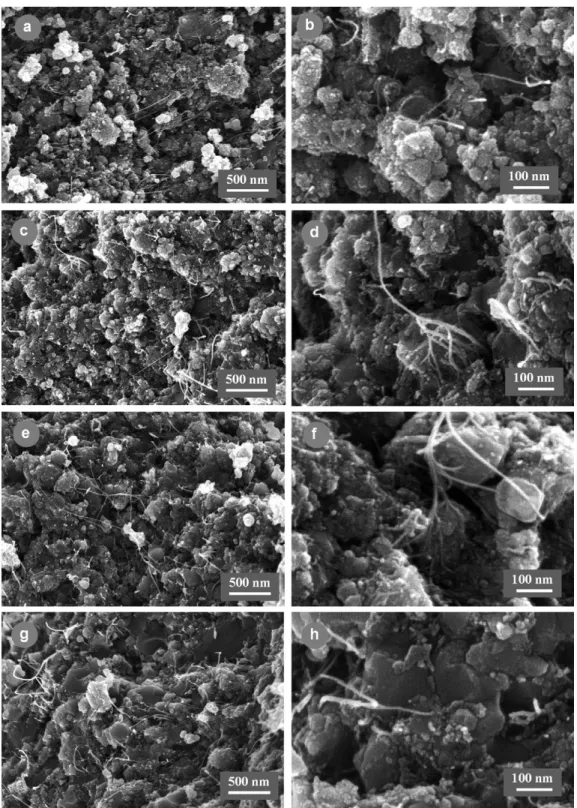
nanoparti-cles (Table 3). The trend is that the hot-pressed densification increases (from 74.2 to 85.5%) upon the increase of the hot-pressing temperature (Table 2). For the specimen hot-pressed at 1300◦C, a higher green densification than expected was obtained, probably caused by a pressure exceeding 100 MPa dur-ing the cold-pressdur-ing, and results in a HP densification similar to that of the specimen hot-pressed at 1400◦C. FEG-SEM images of fracture surfaces are reported in Fig. 1. Most of the spinel matrix grains of the composites hot-pressed at 1200 and 1300◦C (Fig. 1a–d) have a diameter smaller than 100 nm and form larger agglomerates, similarly to what can be observed in the start-ing powder (Fig. 2d). By contrast, most grains have grown in the composite hot-pressed at 1500◦C, some reaching more than 500 nm (Fig. 1g–h), while at 1400◦C only some matrix grains seem to have grown (Fig. 1e and f). We also observe many CNT (or CNT bundles) that have not been broken, or have been broken after some pull-out, whereas CNT that may have been broken at the level of the fracture surface cannot be observed. For each hot-pressing temperature, the observations conducted in many areas and on several specimens, show that CNT (or CNT bundles) are always evidenced, in agreement with their very homogeneous distribution within the composite powders (Fig. 2d). However, it appeared also that many CNT have been damaged in the com-posite hot-pressed at 1500◦C, and also in a lesser extend in that hot-pressed at 1400◦C, producing some short CNT residues or carbon clusters at the grain boundaries and grain junctions of the matrix (Figs. 1h, 1f). As a result of this preliminary study, 1300◦C was thought to be a low enough temperature so as to not damage the CNT and therefore was chosen as the hot-pressing temperature for the rest of the work.
3.2. Influence of the content of carbon nanotubes
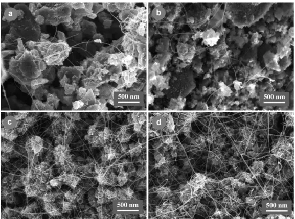
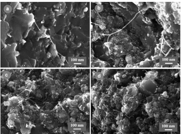
Typical FEG-SEM images of composite powders, revealing the increasing quantity of CNT, are shown in Fig. 2. These images show also some differences in the microstructure of the matrix grains. The C powders (Fig. 2a and b) contain relatively
Fig. 1. FEG-SEM images of the fracture surfaces of the 15.5 vol.% CNT–Co/Mo–MgAl2O4composite (specimen CM7) hot-pressed at different temperatures: (a
and b) 1200◦C; (c and d) 1300◦C; (e and f) 1400◦C; (g and h) 1500◦C.
non-porous grains (up to 500 nm large) which are made up of well sintered primary grains, some of these large grains hav-ing a plate-like form. The CM powders (Fig. 2c and d) contain porous agglomerates of much smaller grains (generally less than 100 nm). This difference is consistent with the specific surface area of the solid solution powders before reduction which are around 20 and 40 m2/g, for C and CM powders, respectively. In all powders, the CNT network forms a very well distributed
interconnected web. In C powders, this web is formed of fil-aments with small diameters, most being probably individual CNT (Fig. 2a and b) whereas, in CM powders (Fig. 2c and d), this web is very dense and formed of bundles, up to 10–20 nm in diameter, made up of several CNT. The specimens do not contain any large MWNT, carbon fibres nor disordered carbon. Statistical studies on HRTEM images have shown that 70–90% of the CNT are SWNT, most of the others being DWNT. The
Fig. 2. FEG-SEM images of some CNT–Co/Mo–MgAl2O4composite powders: (a) specimen C1, (b) specimen C3, (c) specimen CM1 and (d) specimen CM7.
CNT diameter is in the 0.5–5 nm range with a mean diameter between 2.4 and 2.8 nm. From these common characteristics, a CNT density of 1.70 was calculated and was used to calculate the CNT vol.% from the experimental CNT in wt% (Table 3). X-ray diffraction revealed the presence of-Co besides the MgAl2O4
matrix in all specimen and of some Mo2C in CM specimens.
From the chemical composition of the starting catalytic materi-als, taking into account that the reduction of Co2+ in Co0was complete,30 we have deduced the volume contents in-Co and Mo2C (Table 3) and it is noted that the values are not higher than
3.08 and 2.47 vol.%, respectively. Calculations showed that the
carbon contained in Mo2C is negligible when compared to that
in the CNT.
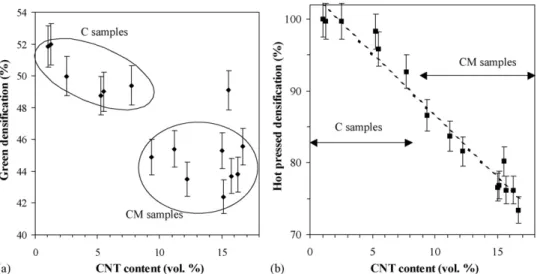
The green densification (Table 3andFig. 3a) of the C speci-men tends to decrease, from 52 to 49%, when the CNT content is increased from 1.2 to 7.7 vol.%. The CM specimens (CNT con-tent from 9.4 to 16.7 vol.%) have a green densification around 45%, lower than that of the C specimens, except specimen CM7 whose higher than expected green densification was caused by a pressure exceeding 100 MPa during the cold-pressing. The hot-pressed densification for specimen containing more than 5 vol.% of CNT (Table 3andFig. 3b) regularly decreases when the CNT
Table 3
Characteristics of the CNT–metal–MgAl2O4composites hot-pressed at 1300◦C: Co and Mo2C contents (vol.%) calculated from the composition of the specimen;
Cnand Cv, the measured carbon content (wt.%) and the corresponding calculated carbon content (vol.%) taken as the CNT content; green d, green densification; HP
d, hot-pressed densification
Specimen Co (vol.%) Mo2C (vol.%) Cn(wt.%) Cv(vol.%) Green d (%) HP d (%)
C1 0.32 0 0.55 1.2 51.9± 1.3 100.0± 2.6 C2 1.93 0 0.6 1.3 51.8± 1.3 99.8± 2.5 C3 2.31 0 1.4 2.5 50.0± 1.3 99.7± 2.5 C4 3.14 0 2.5 5.3 48.8± 1.2 98.3± 2.5 C5 3.13 0 2.6 5.5 49.0± 1.2 95.6± 2.4 C6 3.08 0 3.7 7.7 49.4± 1.2 92.7± 2.3 CM1 1.51 1.30 4.4 9.4 44.9± 1.1 86.6± 2.2 CM2 2.86 2.47 5.1 11.2 43.5± 1.1 83.8± 2.1 CM3 2.89 1.25 6.4 12.2 45.4± 1.1 81.0± 2.0 CM4 2.79 2.41 7.0 15.1 42.4± 1.1 76.9± 1.9 CM5 1.44 1.25 7.2 15.0 45.3± 1.1 76.6± 1.9 CM6 2.78 2.40 7.3 15.7 43.7± 1.1 76.2± 1.9 CM7 0.73 1.25 7.5 15.5 49.0± 1.2 80.2± 2.1 CM8 2.83 1.22 7.8 16.3 43.8± 1.1 76.2± 1.9 CM9 2.82 1.22 8.0 16.7 45.6± 1.1 73.4± 1.8
Fig. 3. Green densification (a) and hot-pressed densification (b) vs. the CNT content in the hot-pressed CNT–Co/Mo–MgAl2O4composites.
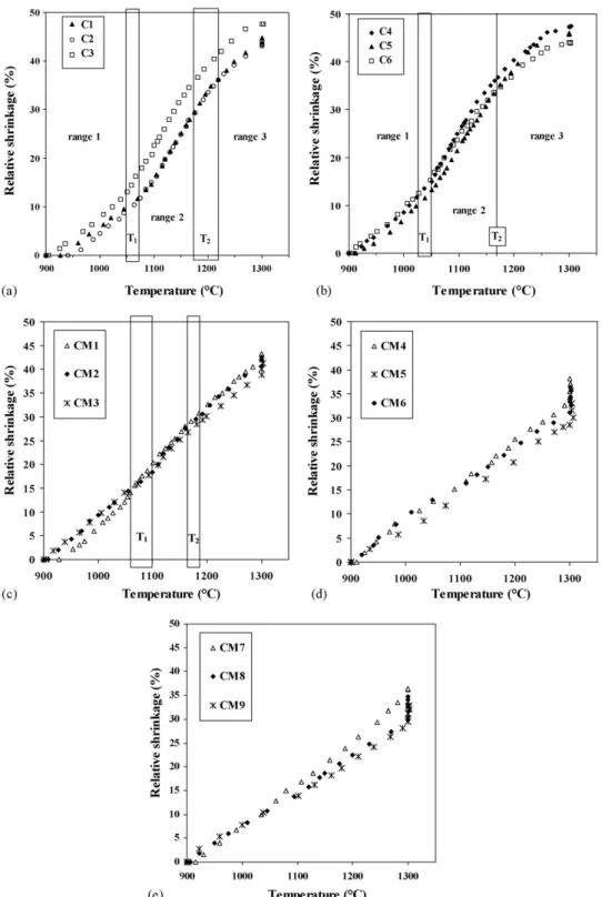
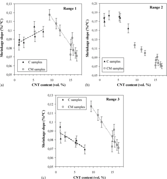
content increases, reaching only 73.4% for CM9 (16.7 vol.% CNT). The relative shrinkage versus temperature for the C com-posites, prepared using only cobalt as a catalytic metal, is shown inFig. 4a and b. For these specimens, the shrinkage curves have similar shapes and, when the CNT content increases, they differ only by slight shifts towards lower temperatures and some vari-ations in shrinkage slopes. To permit a comparison between the shrikage slopes, we divided the curves in three ranges (Fig. 4a and b), firstly between 900◦C and T1, secondly between T1and
T2and thirdly between T2and 1300◦C. The transition
temper-atures were chosen at values at which the shrinkage is no more almost linear, but notably increases at T1and notably decreases
at T2. Possibly, changes in the dominant mechanism occur at
these temperatures, but that could be confirmed only by further studies related to the kinetic of shrinkage. For each of the C specimen, the values of T1and T2are reported inTable 4. For
increasing CNT contents, both tend to decrease (from 1070 to 1030◦C and from 1220 to 1170◦C, respectively). We calculated that at these temperatures, the C specimens have similar relative
densities, respectively, equal to (60.0± 0.5%) and (82 ± 1%). The shrinkage slopes in each of the three ranges, obtained by a linear fitting, are reported inTable 4. Note that since the heat-ing rates are constant (10± 1◦C/min) the comparisons of the shrinkage slopes (%/◦C) are representative of that of the shrink-age rates (%/min), but we keep the slope as the parameter to avoid any confusion with isothermal studies.
It is well known that, in the first step of hot-pressing, the shrinkage is mainly due to particle rearrangement towards more dense packing.31We infer that for the present C specimen, this mechanism is the dominant one in the range 1. It normally leads to a relative density around 60%31 which is effectively obtained at T1. In spite of the initial cold-pressing operated
at 100 MPa, some rearrangement could occur at 900–1050◦C under 43 MPa because the green relative densities are still low (Table 3) and the thermal expansion upon heating creates inter-nal stresses in the packing which can facilitate the mobility of particles. For increasing CNT contents, the shrinkage slope of the C specimen tends to increase (Table 4andFig. 5a). The end
Table 4
Shrinkage slope (%/◦C) in different temperature ranges for C and CM specimen hot-pressed at 1300◦C Specimen Cn(vol.%) T1(◦C) T2(◦C) Shrinkage slopes (%/◦C)
Range 1, 900–T1(◦C) Range 2, T1–T2(◦C) Range 3, T2–1300 (◦C)
C1 1.2 1070 1220 0.084± 0.006 0.178± 0.010 0.095± 0.005 C2 1.3 1070 1220 0.089± 0.006 0.170± 0.010 0.081± 0.005 C3 2.5 1050 1180 0.086± 0.006 0.184± 0.010 0.084± 0.005 C4 5.3 1050 1170 0.104± 0.006 0.181± 0.010 0.077± 0.005 C5 5.5 1030 1170 0.093± 0.006 0.178± 0.010 0.079± 0.005 C6 7.7 1030 1170 0.099± 0.006 0.155± 0.010 0.069± 0.005 CM1 9.4 1060 1160 0.108± 0.007 0.134± 0.011 0.100± 0.006 CM2 11.2 1100 1180 0.096± 0.008 0.131± 0.012 0.095± 0.007 CM3 12.2 1100 1180 0.093± 0.009 0.116± 0.013 0.087± 0.008 CM4 15.1 – – 0.084± 0.006 CM5 15.0 – – 0.073± 0.006 CM6 15.7 – – 0.078± 0.006 CM7 15.5 – – 0.091± 0.006 CM8 16.3 – – 0.074± 0.006 CM9 16.7 – – 0.071± 0.006
Fig. 4. Relative shrinkage vs. temperature for all CNT–Co/Mo–MgAl2O4composites: (a) specimen C1–C3, (b) specimen C4–C6, (c) specimen CM1–CM3, (d)
specimen CM4–CM6 and (e) specimen CM7–CM9.
temperature (T1) of the first step decreases from 1070 to 1030◦C
(Table 4) because the temperature at which the relative density of 60% is reached decreases when the shrinkage slope increases. It has been shown that, at room temperature, an increase con-tent of CNT in a ceramic matrix composite lower the coefficient of friction,7,14 either by the action of rolling or slidding.7 In
the present composite powders, a lot of CNT and CNT bun-dles are located between matrix grains. So it is reasonable to
infer that CNT facilitate the sliding at grain contacts, explain-ing the notable increase of the shrinkage slope with the CNT content.
For higher densifications, i.e. above T1, the shrinkage slope
increases because another mechanism may possibly become predominant. The second step of hot-pressing is usually the shrinkage of the open channel porosity via plastic flow and/or lattice diffusion31and leads to a relative density around 90%. In
Fig. 5. Shrinkage slope vs. the CNT content of the hot-pressed CNT–Co/Mo–MgAl2O4composites for different temperature ranges: (a) 900C–T1, (b) T1–T2and
(c) T2–T3. For C specimen and CM1–CM3 specimen, the values of T1 and T2 are reported inTable 4. For C1–C6 and CM1–CM3 specimen, the shrinkage slopes
were obtained by linear fitting of the curve shrinkage vs. temperature, in each of the three ranges. For CM4–CM9 specimen, the shrinkage slopes were obtained by a unique linear fitting between 900 and 1300◦C.
the present work, a densification of only (82± 1%) is reached at the end of range 2 showing that the shrinkage of the open channel porosity continues during a part of range 3. For the C specimens, as a function of the CNT content (Table 4), the shrinkage slopes in the ranges 2 and 3 (Fig. 5b) begin to decrease clearly only for C6 (7.7 vol.%). To assess a dominant mechanism during the second step of hot-pressing, the values of the pressure, the tem-perature and the particle size must be considered.31In our case, if the pressure is moderate and the particle are of submicrometric size, which speaks in favour of boundary and/or lattice diffu-sion, the temperature is also rather low which speaks in favour of plastic flow. Using powders of 0.13–0.15m particle size and moderate applied pressures (5–38 MPa), Ting and Lu32,33 studied the rate-determining mechanism involved in the hot-pressing of MgAl2O4as a function of the stoichiometry. They
showed that the Nabarro–Herring diffusion creep dominates the densification in low stress regimes. They also showed that the transition stress at which the mechanism changes from diffusion creep to dislocation creep is lower when the spinel has an excess
of Al2O3, in agreement with the variation the concentration of
oxygen vacancy which controls the lattice diffusion.
In the present composite specimens, because Co2+ ions present in the starting solid solution have been reduced to the metallic state, the resulting MgAl2O4is not stoechiometric but
rather with an an excess of Al2O3.30 This excess increases
from C1 to C4, in relation with the increasing Co2+ content in the starting solid solution (from 1 to 20 cat.%—Table 1). In comparison with the works of Ting and Lu,32,33the present spec-imens contain a relatively large excess of Al2O3, we use a slight
higher pressure (43 MPa versus 38 MPa) and lower temperatures (900–1300◦C versus 1450 or 1550◦C). So, it is difficult to settle between the two dominant mechanisms proposed by Ting and Lu.32,33Some-Co nanoparticles are located at the surface of
spinel grains and they could act on the shrinkage mechanism. From the specimens C1 to C5, in spite of the fact that both-Co and the CNT contents increase (from 0.32 to 3.13 vol.% and from 1.2 to 5.5 vol.%, respectively), the shrinkage remains constant (Table 4andFig. 5b). Thus, within these content ranges, neither
-Co nanoparticles nor CNT influence the kinetic of the domi-nant mechanism. In comparison to C5, the C6 specimen contains a similar quantity of-Co but a clearly higher quantity of CNT, resulting in lower shrinkage slopes in ranges 2 and 3 (Fig. 5b and c), without shifts of the transition temperatures (Table 4). Thus, it appears that, when their amount become sufficient (7.7 vol.% for C6), CNT clearly inhibit the shrinkage mechanisms involved in ranges 2 and 3.
The CM specimens will now be considered. They differ from each other firstly (and mainly) by the CNT content, secondly (but to a lesser extent) by the Al2O3excess in the spinel and thirdly
by the-Co and Mo2C contents (Table 3). Only CM1, CM2 and
CM3 specimen have relative shrinkage curves (Fig. 4c) made up of three steps similar to those of the C specimens (Fig. 4a and b), but with a narrower range 2, beginning at a higher tem-perature T1and ending at a lower temperature T2(Table 4). The
densification at T1is around 59, 62 and 64% for CM1, CM2 and
CM3, respectively, not very far from that of the C specimens at T1 (around 60%). For CM4–CM9, the shrinkage is clearly
almost linear from 900 to 1300◦C (Fig. 4d and e andTable 4) and continues during the dwell time at 1300◦C, in contrast with the C specimens (Fig. 4a and b). This is consistent with the low densification achieved (70–80%) at the beginning of the dwell time at 1300◦C. The shrinkage slopes for the CM specimens are plotted on the same graphs as those of the C specimen versus the CNT content (Fig. 5a–c). For CM specimen, in each of the three temperature ranges, the trend is clearly that the slope decreases when the CNT content increases. In the range 1, CM1–CM3 specimen have a slightly higher or similar shrinkage slope than that of C4–C6 (Fig. 5a). But in contrast to what is observed for the C specimens, the slope decreases with the CNT con-tent, from CM1 to CM9 (Fig. 5a). It is well known that CNT have a very high Young modulus. Moreover, in the CM sam-ples, they form a dense web-like structure extensively branched all around the matrix grains (Fig. 3c and d). This web-like struc-ture is detrimental to the mobility of the matrix grains and the rearrangement is probably notably hindered. This phenomenon would be all the more pronounced when the CNT web is more interconnected and more dense, i.e. when the quantity of CNT is increased, from CM1 to CM9.
In range 2, the shrinkage slopes are lower for CM specimens than for C specimens (Fig. 5b) and clearly tend to decrease when the CNT content increases. In range 3, the shrinkage slopes are lower for the CM than for the C specimens (Fig. 5b) and clearly tend to decrease when the CNT content increases. In spite of the fact that CM samples differ also, one from the other, by their Al2O3excess, their-Co and their Mo2C contents, the
inhibi-tion of the shrinkage shows a good correlainhibi-tion only with the regular increasing quantity of CNT from CM1 to CM9. Thus, the study of the CM specimens confirms that CNT over 5 vol.%, greatly inhibit the densification mechanism(s). As will be con-firmed below, the matrix grain growth stays, at this stage, almost ineffective. Consequently, most CNT are still located at grain boundaries, and thus cannot directly inhibit the creep within the matrix grain, as can usually do precipitated second phase par-ticles. A possible explanation is a mechanical role of the CNT which could redistribute the stresses in transversal directions,
decreasing the shear stresses in the longitudinal direction and thus inhibiting the dislocation creep, if this mechanism is dom-inant. Ting and Lu32,33point out that for compositions with an excess of Al2O3, the relative density can reach a plateau. This
could explain the progressive lowering of the shrinkage slope from T2to 1300◦C for C and CM1–CM3 specimens. In
con-trast, this plateau of relative density would not be reached for CM4–CM9 specimens which could explain that the shrinkage remains linear up to 1300◦C (Table 4andFig. 5b and c).
High resolution SEM images of the fracture surface of some hot-pressed specimen are shown inFig. 6. The C2 spec-imen (Fig. 6a), which contain only 1.3 vol.% CNT, presents a mainly transgranular fracture mode, which is characteristic of metal–ceramic nanocomposites, when many metal nanoparti-cles are located within the matrix grains. In this sample, most grains are larger than 200 nm and the smaller grains of the pow-der (Fig. 1a and b) are not observed anymore in the hot-pressed specimen. A significant grain growth has occurred and allowed the complete elimination of the discontinuous porosity (rela-tive densifity of 99.8%—Table 3). The fracture surface of C6 (Fig. 6b), which contains 7.7 vol.% CNT, is somewhat differ-ent from that of C2. Many grains are smaller than 200 nm, some being not larger than 10–20 nm. These nanometer grains perhaps correspond to the-Co nanoparticles which have been covered by carbon capsules during the CNT synthesis. The fact that these particles kept their nanometer size suggests that they did not reached the liquid state during the hot-pressing. Some pores are observed and their size is of the order of the larger matrix grains, which is consistent with the uncompleted elimination of the dis-continuous porosity (relative density of 92.7%—Table 3). Only some CNT are observed on the fracture surface of C2 and C6 but the amount of CNT in the composites CNT is under-estimated on the images. The reason is that most of CNT, and particularly those which are at intragranular positions, have been broken at the level of the fracture surface and cannot be seen on SEM images. On the fracture surface of CM3 and CM4 (Fig. 6c and d), which contain 12.2 and 15.1 vol.% CNT, respectively, much more CNT are observed because of the inherently higher content but also because many CNT, located in the large pores, have not been broken. The fracture of these specimens is mainly inter-granular because the matrix grains are much smaller than that of C2 or C6 specimens. Only some grains reach 200 nm in CM3 (Fig. 6c) and a lot of primary grains of the agglomerates in the powder still remain in the hot-pressed specimen, particularly in CM4. As expected from the relative densities (81.0 and 76.9% for CM3 and CM4, respectively) and the shape of the shrink-age curves (Fig. 4c and d), many large pores which belong to the open channel porosity and are located between the agglomerates have not been eliminated.
Using hot-pressing at higher temperatures (1450–1500◦C), it was shown that the inhibition of matrix grain growth usually provoked by the presence of metal nanoparticles is enhanced by the CNT.20 The elimination of the larger pores can thus not be effective, resulting in an unsufficient densification.20However, some diffusion mechanisms operate at these higher tempera-tures, as shown by a significant begining of grain growth. Thus, CNT located at the grain boundary probably inhibit the mobility
Fig. 6. FEG-SEM images of the fracture surfaces of some CNT–Co/Mo–MgAl2O4composite hot-pressed at 1300◦C: (a) specimen C2, (b) specimen C6, (c) specimen
CM3 and (d) specimen CM4.
of the grain boundaries, as usally do precipitated second phase particles. Consequently, increasing the hot-pressing temperature too much is not efficient and, in any case, a moderate temper-ature is preferable to stay at in order to prevent the damaging of CNT. A better solution would be a higher applied pressure, firstly to crush the matrix grain agglomerates, secondly to obtain a higher efficiency of the plastic flow. Finally, the microstructure of the green sample has to be optimised, particularly to avoid the presence of large inter-agglomerate pores. These pores are much more difficult to eliminate at moderate pressure when the specimen contains a great quantity of CNT which, owing to their high rigidity, decrease the shear stresses within the compact.
Zhan et al.5 have shown that CNT–Al2O3composites
pre-pared by mechanical mixing of CNT and nanometric Al2O3
powder can be well densified by the spark plasma sintering technique. This technique allows the use of a nanometric Al2O3
powder, which is beneficial to the quality of the green specimen. But the disadvantages are a lesser homogeneous distribution of CNT and certainly significant damages to CNT during the very long ball-milling step.5 We proposed that a part of the detri-mental influence of CNT on the densification could be due to their exceptional mechanical properties. So, signicant damages to CNT, detrimental to their rigidity, and a lesser distribution of CNT within the matrix probably favour a better densification on hot-pressing or upon SPS. However, the use of the SPS technique allows to sinter in very short times, limiting the matrix grain growth and probably the damaging of CNT. The first works of the present authors using the SPS technique to sinter CNT–metal oxide nanocomposites with high CNT contents have shown that,
in comparison to hot-pressing, the relative density is increased but not up to the theoretical density. It appears also that applied pressures higher than 43 MPa (i.e. 100 or 150 MPa) are prefer-able. However, the use of nanometric and non-agglomerated matrix powders, which allows to prepare green specimens hav-ing a microstructure more favourable to the densification, is also useful.
4. Conclusions
A study of the densification by hot-pressing of ceramic– matrix composites containing a dispersion of CNT (70–90% being SWNT and most of the others being DWNTs) is pro-posed for the first time. A family of 15 different CNT–Co/ Mo–MgAl2O4composite powders containing between 1.2 and
16.7 vol.% CNT was prepared by CCVD. The in situ growth of CNT within the oxide powder permitted to obtain a highly homogeneous distribution of the CNT which forms a web-like structure all around the matrix grains. The hot-pressing was per-formed under 43 MPa at a constant heating rate of 10◦C/min. A preliminary study led to limit the maximum temperature at 1300◦C to prevent CNT damages. The influence on sintering of the CNT and that of other microstructural characteristics of the starting materials were discriminated. At low contents (below 6 vol.%), CNT are beneficial to the rearrangement pro-cess involved in the first shrinkage step. We proposed that CNT have a lubricating role which facilitates the sliding at grain con-tacts or boundaries. But, at higher contents, CNT inhibit this process. We proposed that, for this CNT contents, their web-like
structure becomes very well interconnected, very rigid, and thus inhibits the rearrangement process. During the second shrink-age step, CNT clearly inhibit the shrinkshrink-age, and this detrimental effect regularly increases with the CNT content. Although it was not possible to settle precisely to the involved mechanism, we proposed that CNT decrease the shear stresses in the longitudi-nal direction, redistribute the stresses in transversal directions, thus inhibiting the plastic flow. Higher applied pressures could be efficient to compensate this detrimental effect. At higher tem-peratures, the shrinkage mechanism would involve some grain growth but CNT tend to be damaged. Moreover, previous studies have shown that at these stages, CNT inhibit the grain growth probably because they inhibit the mobility of the grain bound-aries, as usually do precipitated second phase particles. Thus, hot-pressing at higher temperatures is not efficient to fully den-sify the present materials. Preliminary works showed that the use of spark plasma sintering lead to a better densification of the present materials.
References
1. Laurent, C. and Peigney, A., Carbon nanotubes in composite materials. In Encyclopedia of Nanoscience and Nanotechnology, ed. H. S. Nalwa. Am. Sci. Pub., 2004, pp. 635–653.
2. Peigney, A. and Laurent, C., Carbon nanotubes ceramic composites. In Ceramic Matrix Composites: Microstructure–Property Relationship, ed. I. M. Low. Woodhead Publishing Limited, Cambridge, England, 2006, pp. 309–333.
3. Ma, R. Z., Wu, J., Wei, B. Q., Liang, J. and Wu, D. H., Processing and properties of carbon nanotube/nano-SiC ceramic. J. Mater. Sci., 1998, 33, 5243–5246.
4. Ning, J., Zhang, J., Pan, Y. and Guo, J., Fabrication and mechanical prop-erties of SiO2 matrix composites reinforced by carbon nanotube. Mater.
Sci. Eng. A: Struct. Mater. Prop. Microstruct. Process., 2003, A357, 392–396.
5. Zhan, G.-D., Kuntz, J. D., Wan, J. and Mukherjee, A. K., Single-wall carbon nanotubes as attractive toughening agents in alumina-based nanocompos-ites. Nat. Mater., 2003, 2, 38–42.
6. Wang, X., Padture, N. P. and Tanaka, H., Contact-damage-resistant ceramic/single-wall carbon nanotubes and ceramic/graphite composites. Nat. Mater., 2004, 3, 539–544.
7. Lim, D. S., You, D. H., Choi, H. J., Lim, S. H. and Jang, H., Effect of CNT distribution on tribological behavior of alumina–CNT composites. Wear, 2005, 259, 1–6 (Part 1 Special Issue SI, 539–544).
8. Fan, J., Zhao, D., Wu, M., Xu, Z. and Song, J., Preparation and microscruc-ture of multi-wall carbon nanotubes-toughened Al2O3 composite. J. Am.
Ceram. Soc., 2006, 89, 750–753.
9. Peigney, A., Laurent, C., Dobigeon, F. and Rousset, A., Carbon nanotubes grown in situ by a novel catalytic method. J. Mater. Res., 1997, 12, 613–615. 10. Laurent, C., Peigney, A. and Rousset, A., Synthesis of carbon nanotube– Fe–Al2O3 nanocomposite powders by selective reduction of different
Al1.8Fe0.2O3solid solutions. J. Mater. Chem., 1998, 8, 1263–1272.
11. Govindaraj, A., Flahaut, E., Laurent, C., Peigney, A., Rousset, A. and Rao, C. N. R., An investigation of carbon nanotubes obtained from the decompo-sition of methane over reduced Mg1−xMxAl2O4spinel catalysts. J. Mater.
Res., 1999, 14, 2567–2576.
12. Flahaut, E., Govindaraj, A., Peigney, A., Laurent, C., Rousset, A. and Rao, C. N. R., Synthesis of single-walled carbon nanotubes using binary (Fe,
Co, Ni) alloy nanoparticles prepared in situ by the reduction of oxide solid solutions. Chem. Phys. Lett., 1999, 300, 236–242.
13. Flahaut, E., Peigney, A., Laurent, C. and Rousset, A., Synthesis of single-walled carbon nanotube–Co–MgO composite powders and extraction of the nanotubes. J. Mater. Chem., 2000, 10, 249–252.
14. An, J. W., You, D. H. and Lim, D. S., Tribological properties of hot-pressed alumina–CNT composites. Wear, 2003, 255, 677–681.
15. Liu, Y. Q. and Gao, L., A study of the electrical properties of carbon nanotube–NiFe2O4composites: effect of the surface treatment of the carbon
nanotubes. Carbon, 2005, 43, 47–52.
16. Mo, C. B., Cha, S. I., Kim, K. T., Lee, K. H. and Hong, S. H., Fabrication of carbon nanotube reinforced alumina matrix nanocomposite by sol–gel process. Mater. Sci. Eng. A: Struct. Mater. Prop. Microstruct. Process., 2005, A395, 124–128.
17. Huang, Q. and Gao, L., Manufacture and electrical properties of multiwalled carbon nanotube/BaTiO3nanocomposite ceramics. J. Mater. Chem., 2004,
14, 2536–2541.
18. Laurent, C., Peigney, A., Dumortier, O. and Rousset, A., Carbon nanotubes Fe alumina nanocomposites. Part II. Microstructure and mechanical proper-ties of the hot-pressed composites. J. Eur. Ceram. Soc., 1998, 18, 2005–2013. 19. Peigney, A., Laurent, C., Flahaut, E. and Rousset, A., Carbon nanotubes in
novel ceramic matrix nanocomposites. Ceram. Int., 2000, 26, 677–683. 20. Flahaut, E., Peigney, A., Laurent, C., Marliere, C., Chastel, F. and
Rous-set, A., Carbon nanotube–metal–oxide nanocomposites: microstructure, electrical conductivity and mechanical properties. Acta Mater., 2000, 48, 3803–3812.
21. Rul, S., Lefevre-schlick, F., Capria, E., Laurent, C. and Peigney, A., Percola-tion of single-walled carbon nanotubes in ceramic matrix nanocomposites. Acta Mater., 2004, 52, 1061–1067.
22. Zhan, G.-D., Kuntz, J. D., Garay, J. E. and Mukherjee, A. K., Electrical properties of nanoceramics reinforced with ropes of single-walled carbon nanotubes. Appl. Phys. Lett., 2003, 83, 1228–1230.
23. Sun, J., Gao, L. and LI, W., Colloidal processing of carbon nanotube/alumina composites. Chem. Mater., 2002, 14, 5169–5172.
24. Chan, M. O. B., Seung, C. H. A. I., Kyung, K. I. M. T., Kyung, L. E. E. H. and Hong, S. H., Fabrication of carbon nanotube reinforced alumina matrix nanocomposite by sol–gel process. Mater. Sci. Eng. A: Struct. Mater. Prop. Microstruct. Process., 2005, 395, 124–128.
25. Kingsley, J. J. and Patil, K. C., A novel combustion process for the synthesis of fine a-alumina and related oxide materials. Mater. Lett., 1998, 6, 427–432. 26. Rul, S., Peigney, A., Bacsa, W. S. and Laurent, C., Ceramic foams for the CCVD synthesis of single-walled carbon nanotubes. 2006, submitted for publication.
27. Flahaut, E., Bacsa, R., Peigney, A. and Laurent, C., Gram-scale CCVD syn-thesis of double-walled carbon nanotubes. Chem. Com., 2003, 1442–1443. 28. Flahaut, E., Peigney, A., Bacsa, W. S., Bacsa, R. R. and Laurent, C., CCVD synthesis of carbon nanotubes from (Mg, Co, Mo)O catalysts: influence of the proportions of cobalt and molybdenum. J. Mater. Chem., 2004, 14, 646–653.
29. Rul, S., Laurent, C., Peigney, A. and Rousset, A., Carbon nanotubes prepared in situ in a cellular ceramic by the gelcasting-foam method. J. Eur. Ceram. Soc., 2003, 23, 1233–1241.
30. Quenard, O., Laurent, C., Brieu, M. and Rousset, A., Synthesis, microstruc-ture and oxidation of Co–MgAl2O4 and Ni–MgAl2O4 nanocomposites
powders. Nanostruct. Mater., 1996, 7, 497–507.
31. Coble, R. L., Mechanisms of Densification During Hot Pressin. In Sintering and Related Phenomena, ed. G. C. Kuczynski, N. A. Hooton and C. F. Gibbon. Gordon and Breach, New York, 1967, pp. 329–350.
32. Ting, C. J. and Lu, H. Y., Hot-pressing of magnesium aluminate spinel. I. Kinetics and densification mechanism. Acta Mater., 1999, 47, 817–830. 33. Ting, C. J. and Lu, H. Y., Hot-pressing of magnesium aluminate spinel. II.