HAL Id: tel-02968552
https://tel.archives-ouvertes.fr/tel-02968552
Submitted on 15 Oct 2020HAL is a multi-disciplinary open access archive for the deposit and dissemination of sci-entific research documents, whether they are pub-lished or not. The documents may come from teaching and research institutions in France or abroad, or from public or private research centers.
L’archive ouverte pluridisciplinaire HAL, est destinée au dépôt et à la diffusion de documents scientifiques de niveau recherche, publiés ou non, émanant des établissements d’enseignement et de recherche français ou étrangers, des laboratoires publics ou privés.
Multi-scale study of mechanical behaviour of two-phase
materials during large deformation and ductile damage
Yuchen Zhao
To cite this version:
Yuchen Zhao. Multi-scale study of mechanical behaviour of two-phase materials during large defor-mation and ductile damage. Materials and structures in mechanics [physics.class-ph]. Université de Technologie de Troyes, 2017. English. �NNT : 2017TROY0018�. �tel-02968552�
THESE
pour l’obtention du grade de
D
OCTEUR
de l’U
NIVERSITE
DE
T
ECHNOLOGIE DE
T
ROYES
Spécialité : MATERIAUX, MECANIQUE, OPTIQUE ET NANOTECHNOLOGIE
présentée et soutenue par
Yuchen ZHAO
le 17 juillet 2017
Multi-scale Study of Mechanical Behaviour of Two-phase
Materials during Large Deformation and Ductile Damage
JURY
M. A. LODINI PROFESSEUR EMERITE Président
M. A. BACZMANSKI PROFESSOR Directeur de thèse
Mme V. FAVIER PROFESSEURE DES UNIVERSITES Examinateur
M. V. JI PROFESSEUR DES UNIVERSITES Rapporteur
Mme L. LE JONCOUR MAITRE DE CONFERENCES Directrice de thèse
To my parents
To my dear Yuan
Acknowledgements
As the time flying away, four years of Ph.D. study have fleeted soundlessly. These years are a brief moment for the life, but they are the most colourful days I have never experienced. Without your support and assistance, my doctoral dissertation would not have been possible to be accomplished.
My Ph.D. study has been undertaken mainly in the laboratory LASMIS of University of Technology of Troyes (UTT) and partially in the Faculty of Physics and Applied Computer Science of AGH University of Science and Technology.
Foremost, I would like to express my sincere gratitude to my supervisors, Ms. Léa LE
JONCOUR and Prof. Andrzej BACZMAŃSKI, for their selfless and generous guidance
throughout my study. They enlightened me the first gate of scientific research and taught me not only immense knowledge, which broadened my horizon, but also their personal qualities, such as patience, carefulness, motivation, optimism and enthusiasm, from which I will benefit for the whole life.
Authentic appreciation will also be expressed to Prof. Ru Lin PENG and Prof. Vincent JI, for their valuable comments and advices on my thesis, and to Prof. Véronique FAVIER and Prof. Alain LODINI for their attendance as juries in my Ph.D. defense committee. Their frank suggestions and encouragement greatly improved the scientific quality of this manuscript.
Many thanks go out to the support I received from my colleagues in both UTT and AGH, who gave me lots of help in experimental experiences, equipment usage, specimen preparation, data treatment, information technique and problem discussion. They are Prof. Manuel FRANÇOIS, Prof. Benoît PANICAUD, Mr. Bruno GUELORGET, Mr. Sebastian
WROŃSKI, Mr. Laurent Daniel, Mr. Mirek WRÓBEL, Mrs. Marianna MARCISZKO, Mr.
François WEIL, Prof. Xiaolu GONG and Mr. Zhidan SUN. I am also grateful to my fellow labmates, Mr. Zhaojun TAO, Mr. Jianqiang ZHOU, Mr. Mingchuan WANG, Ms. Elnaz ASADOLLAHIYAZDI, Mr. Donato GALLITELLI, Mr. Kai ZHANG, Mr. Yangcan WU, Mr.
Yipeng HUANG, Mr. Feng TAN, Mr. kamil SOŁODUCHA and to my other friends, for their
kind assistance and for all the fun we have shared in the last four years.
I would also like to thank Mr. Jan PILCH in the institution UJF in Czech Republic and Mr. Vincent KLOSEK in the laboratory LLB CEA Saclay, for their warm welcome and voluntary guidance during the sleepless nights we were working together.
Last but not the least, I would like to show my deepest love to my father, Prof. Wenming ZHAO, my mother Mrs. Zhengping JIA and, especially, to my dear Yuan. It is them who raised me up when I felt disappointed and encouraged me to carry on. Thank you for your unconditional love, which will always be the strongest support in my life.
Yuchen ZHAO
1
Summary
Glossary ... 4
Introduction ... 5
Chapter 1. Research background and material description ... 10
1.1 Description of duplex steels ... 12
1.1.1 Slip mode in duplex steels ... 13
1.1.2 Ductile damage in duplex steels ... 16
1.1.3 Research status ... 17
1.1.3.1 Elasto-plastic deformation of duplex steel ... 17
1.1.3.2 Ductile damage process duplex steel ... 20
1.1.4 Characterisation of studied duplex steels ... 22
1.2 Descriptions of two-phase titanium ... 25
1.2.1 Elasto-plastic deformation in two-phase titanium ... 26
1.2.2 Ductile damage in two-phase titanium... 31
1.2.3 Characterisation of experimental TIMETAL-18 alloy ... 33
1.3 Conclusion ... 37
Chapter 2. Experimental measurements and techniques ... 39
2.1 Measurement by diffraction method ... 39
2.1.1 Physical principles ... 39
2.1.2 Influences of microscopic phenomena on scattering patterns ... 40
2.1.3 Tensile testes coupled with in situ diffraction measurements ... 43
2.1.4 Determination of stress state by diffraction method ... 44
2.1.4.1 Definition of reference systems... 44
2.1.4.2 Measurements of internal stress by X-ray diffraction ... 45
2.1.4.3 Standard � � � method... 47
2.1.4.4 Multi-reflection grazing incidence method ... 49
2.2 Instrumented Indentation Test (IIT) ... 51
2.2.1 Principe of traditional indentation test ... 51
2.2.1 Description of Berkovich indenter ... 53
2.3 Electron Backscatter Diffraction (EBSD) ... 53
2.3.1 Scanning Electron Microscope (SEM) ... 54
2.3.2 Electron BackScatter Diffraction (EBSD) system ... 55
2.3.3 SEM Transmission Kikuchi Diffraction (TKD) ... 57
2.4 Methodologies used in the thesis ... 58
Chapter 3. Elasto-plastic behaviour modelling with ductile damage process ... 59
3.1 Definition of Representative Volume Element (RVE)... 60
3.2 Definition of different scales ... 60
3.3 Approach of scale transition ... 61
3.4 Constitutive equations of multi-scale approach ... 62
3.4.1 Localization from RVE to grains ... 62
3.4.2 Modelling of local behaviour ... 63
2
3.4.2.2 Scale transition from grains to slip systems ... 64
3.4.2.3 Modellling at slip systems scale ... 65
3.4.3 Homogenization from lattice to RVE ... 65
3.4.3.1 Homogenization from slip systems to grains scale ... 66
3.4.3.2 Homogenization from grains to RVE scale ... 67
3.4.4 Synthesis of elasto-plastic self-consistent model ... 68
3.5 Modelling of nonlinear work hardening and ductile damage ... 70
3.5.1 Damage modelling at grains scale ... 70
3.5.2 Damage modelling at slip systems scale ... 72
3.5.2.1 Modelling of linear hardening ... 72
3.5.2.2 Modelling of nonlinear hardening ... 72
3.5.2.3 Equivalent strain criterion for micro-damage process ... 74
3.5.3 Approach of localization with damage effect ... 75
3.6 Conclusion ... 77
Chapter 4. Diffraction study of duplex steel compared with model predictions ... 78
4.1 Experimental set-up and data treatment ... 79
4.2 Initial measurement without external load ... 80
4.3 Strains evolution in the loaded samples during tensile tests ... 84
4.4 Analysis for elasto-plastic deformation with model predictions ... 88
4.4.1 Analysis of neutron diffraction data ... 88
4.4.2 Comparison between neutron and synchrotron diffraction data ... 92
4.5 Time depending damage analysis and damage criteria ... 93
4.5.1 Test of equivalent strain criterion for damage ... 94
4.5.2 Tests of equivalent stress criterion for damage ... 98
4.5.3 Tests of the total energy criterion for damage ... 101
4.5.4 Conclusion concerning damage criteria ... 103
4.6 Space depending analysis and necking behaviour study ... 104
4.6.1 Experimental data treatment ... 107
4.6.2 Analysis during tensile tests ... 108
4.θ.β.1 χnalysis on “Sample TD” ... 109
4.θ.β.β χnalysis on “Sample σD” ... 111
4.6.3 Analysis of spatial scanning results in the necking area ... 112
4.6.4 Finite Element Method (FEM) simulation ... 115
4.8 Conclusions... 119
Chapter 5. Studies of mechanical properties using Instrumented Indentation Test ... 121
5.1 Instrumented Indentation Test on initial specimens ... 121
5.2 Instrumented Indentation Test on fractured specimen ... 124
η.β.1 Evolution of mean hardness and mean Young’s modulus along specimen ... 126
5.2.1.1 Hardness evolution ... 129
η.β.1.β Young’s modulus evolution ... 132
η.β.β Evolution of hardness vs. Young’s modulus ... 133
3
Chapter 6. Studies on α-β titanium alloy Ti-18 ... 137
6.1 Tensile test coupled with X-ray diffraction measurements ... 137
6.1.1 Experimental methodology... 137
6.1.1.1 Determination of elastic lattice strains in transverse direction ... 139
6.1.1.2 Determination of phase stress in loading direction ... 139
6.1.2 Determination of initial stress ... 140
6.1.3 Evolution of stresses in each phase during the tensile test ... 141
6.1.4 Evolution of lattice strain in each phase during the tensile test ... 143
6.2 Confrontation of model prediction with experimental results ... 143
6.2.1 CRSS determined for slip systems ... 144
6.2.2 Evolution of phase strains in transverse direction ... 145
6.2.3 Order of slip activation ... 147
6.2.4 Accumulation of shear strains ... 147
6.2.4.1 Without initial stress ... 148
6.2.4.2 Without initial stress ... 149
6.2.5 Evolution of phase stresses in loading direction ... 149
6.2.6 Evolution of macro-stress in loading direction ... 151
6.3 TKD measurement for Ti-18 microstructure ... 153
6.4 Conclusions... 155
General conclusion ... 157
Perspectives ... 160
Résumé de la thèse en français ... 162
Appendix ... 194
4
Glossary
CRSS: Critical Resovled Shear Stress
EBSD
:
Electron BackScatter Diffraction
EPSC : Elasto-Plastic Self-Consistent
FEM: Finite Element Method
IIT : Instrumented Indentation Test
IQ: Image Quality
MGIXD : Multi-reflection Grazing Incidence X-ray Diffraction
ODF: Orientation Distribution Function
RVE: Representative Volume Element
SEM : Scanning Electron Microscope
TKD: Transmission Kikuchi DIffraction
XEC: X-ray Elastic Constants
XSF: X-ray Stress Factors
BCC: Body Centred Cubic
FCC: Face Centred Cubic
HCP: Hexagonal Close Pcking
RD: Rolling direction
TD: Transverse direction
ND: Normal direction
5
Introduction
Metallic materials, alloys and metal composites are nowadays ones of the most largely used materials. Because of the excellent mechanical properties and the good workability, metallic materials have been applied from underwater operations to the aeronautic and space research. In this case, the quantification of mechanical behaviours of these materials and the understanding of intrinsic properties behind their macroscopic performances are strongly highlighted. On nowadays background of global environmental protection, energy saving and emission reduction, the structure optimization is one of the main topics for industrial design, which urgently requires the characterisation of metallic materials. Besides, despite their outstanding characters, the failure of machine parts caused by large deformation or damage in the metallic materials lead frequently to fatal accidents. In this context, the present thesis is accomplished in the aim of better understanding the mechanical behaviour in metallic materials exhibiting different crystal structures during large deformation, and the intrinsic mechanism of ductile damage process.
Numerous studies have been previously carried out concerning the above mentioned topics [Greenfield 72, Helbert 96, Verhaeghe 97, Helbert 98, Seshacharyulu 00, Filip 03, Krupp 04, Alvarez-Armas 07, Kumar 09, Wang 10, Alvarez-Armas 11, Le Joncour 11, Baczmanski 16], however, several issues still remain unsettled. The macroscopic mechanical response of materials is not only determined by the applied external load, but also depends on their internal mechanical state and their microstructures. The polycrystalline materials are constituted by crystal lattice, grains and phases at different scales. This complex constitution and the influence of forming procedures lead to intrinsic heterogeneities of metallic materials, such as crystallographic texture, residual stress and inter-grains or inter-phases incompatibilities. These microscopic heterogeneities and the mechanical behaviours at lattice scale greatly influence the global mechanical behaviour of metallic materials at macroscopic scale.
To the end of investigating intrinsic properties at lattice level and the interaction between grains and phases, multi-scale approach is applied in this work. The multi-scale approach allows localizing macroscopic behaviours of polycrystal materials to grain scale then to lattice scale. During the scale localization, the mechanical behaviours at mesoscopic (grain) and microscopic (lattice) scales could be investigated. In turn, the microscopic mechanical
6
properties could be used to feedback the mechanical behivours at mecoscopic scale then to determine the macroscopic performance of materials.
In this work, two typical materials, duplex steels and two-phase titanium, largely applied in the industry field, are taken as the study objects.
The duplex steels are consisted of austenite ( phase) and ferrite (α phase) in approximate equal portion. With different cubic lattice structures, the duplex steels allow us to study the mechanical properties of cubic lattices, as well as the interaction between them. α-β titanium alloy, exhibiting hexagonal α phase and cubic phase, is studied in this thesis. This two-phase composition provides us an opportunity to look into the interaction between cubic and hexagonal lattice as well as to characterize the mechanical properties of hexagonal lattice.
Besides the observation of microscopic mechanical behaviour during large deformation, studies of initiation of ductile damage are also an important part of this thesis. Currently, most research work about the ductile damage is based on the ex situ measurement or observation, which makes it difficult to interprete the experimental results. The study of post-fracture samples, for instance the microscopic observation or EBSD (Electron Backscatter Diffraction) analysis on fracture surface or on the cut section along necking, allow obtaining a direct observation on the fracture, but they are limited to static results thus short of information about the dynamic evolution of ductile damage process.
The diffraction measurement is considered as an appropriate experimental method to study behaviour of polycrystalline materials at mesocale, thanks to its selectivity and the possibility of non-destructive measurement. Diffraction-based techniques are powerful tools to study the stress states and the mechanical behaviour of polycrystalline solids at both microscopic and mesoscopic (grains) scales [ψaczmański λλ, Gloaguen 02, ψaczmański 04a, Gloaguen 04, Fréour 05, Dakhlaoui 07, Wroński 07, Le Joncour 10, ψaczmański 11, Gloaguen 13]. The selectivity provided by diffraction method allows measuring separately the mechanical properties of each phase in multiphase polycrystalline materials during small deformation stage.
The diffraction techniques in this present work mainly involve the neutron and X-ray diffraction methods. Due to the low absorption of neutron radiation in certain studied materials, the internal volume of samples can be studied. As well, high-energy X-ray
7
polycrystalline specimen. In addition, the X-ray synchrotron sources provide fine collimation and strong intensity, which make possible high-spatial-resolution measurements.
Besides, the ability of non-destructive measurement enables in situ measurement during the large deformation process. Combinating with stress correction method proposed by [Le Joncour 10], the real stress applied along the necking of experimental sample can be determined after appearance of necking phenomenon. Using this method, the mechanical behaviour of aimed material can be followed during the whole tensile test.
In terms of quantification studies, digital simulations based on the self-consistent algorithm are compared to the experimental results. The experimental results obtained from diffraction measurements are compared and fitted by the self-consistent model in order to determine essential parameters related to the elastic and plastic deformation in different phases of materials. A newly developed self-consistent model, which additionally includes the modelling of ductile damage process, is applied to analysis non-linearity work hardening and the initiation of ductile damage.
The aim of present works is to improve our current knowledge on the mechanical behaviour of different metallic materials, moreover to quantify the microscopic strain evolution of different lattices during external mechanical solicitation. This manuscript gathers our studies and thought on the following issues: the evolution of mechanical behaviours in polycrystalline materials, the interaction between grains and phases under external load, the activation of plastic deformation and the initiation of ductile damage, the quantification of material properties by comparing experimental data with digital predations. All of these concerned points will be presented and discussed in four main parts. The main objectives of this work are following:
- Determination of critical resolved shear stresses and work hardening parameters of
slip systems for duplex steel and two-phase Ti-alloy. To do this, elastic strain of grains
aggregate belonging to both phases in two-phase titanium and duplex steel will be studied by diffraction method. Then the experimental results will be compared with self-consistent model.
- Verification of criterion for damage initiation using ductile damage model integrated
8
the deformation neck in duplex steel will be compared with model prediction. Different criteria will be used in simulations.
- Confirmation of previous results on duplex steel obtained by in situ diffraction
measurement and further investigation on spatial stress relaxation (damage initiation) during large deformation stage. The mechanical behaviours of each phase in duplex steel
have been studied by Le Joncour et al. [Le Joncour 11]. These results will be confirmed in this thesis using different experimental methods. Then, the heterogeneity of lattice strains along the necking area will be analysed.
- Observation of hardness evolution and Young’s modulus heterogeneity within the necking. The nano-indentation measurements will be done on the surface of the neck, after
fracture of sample made of duplex steel.
In this thesis, the chapter 1 presents bibliographic synthesis about the state of the art on the related studied filed. The chapter 1 summarises the background of research work on duplex steels and two-phase titanium alloys. The activation modes of plastic deformation in cubic and hexagonal lattices are also presented. As well, the assumptions proposed by previous literatures about initiation of damage process in both materials are also discussed.
The chapter 2 focuses on the description of techniques employed in the experimental works. The principale of diffraction measurements, the method of stress determination by diffraction, and the Instrumented Indentation Test (IIT) are described successively in this chapter.
The chapter 3 presents the modelling of elasto-plastic behaviour of polycrystalline materials based on multi-scale self-consistent model. The Eshelby-Kröner grains interaction model is applied in this algorithm. The anisotropy of materials at different scales, such as crystallographic constants of lattices, the grains orientations and the stiffness tensor of different phases, is taken into account. Moreover, a recently developed modelling for ductile damage initiation will be introduced in this chapter, which allows extending the original self-consistent model to the scope of ductile damage process in multi-phase materials.
The chapter 4 is dedicated to the presentation of in-situ diffraction measurements coupled with tensile tests on duplex steels. Then, the experiment results will be analysed by predictions of multi-scale self-consistent models, several essential parameters are determined for the elasto-plastic behaviour of duplex steels, as well as for the initiation of ductile
9
damage in ferritic phase. Studies of stress and strain partitioning between phases in duplex
steel during the necking process are described. High resolution in situ synchrotron measurement is applied to perform scans along the neck.
In chapter 5, an original Instrumented Indentation Test (IIT) have been done on duplex steel after the sample fracture, in order to investigate the evolution of microstructure and mechanical properties from the little deformed part of sample until its fracture surface. In comparison with diffraction measurements data, some intresting relationships between phases’ mechanical behaviours and the evolution of hardness and Young’s modulus are found.
Chapter 6 presents studies on the evolution of stress and strain in each phase of titanium during tensile test using in-situ X-ray diffraction. Fitting of experimental results with model prediction is also performed using elasto-plastic self-consistent model in order to find appropriate values for parameters associated with the activation of slip systems in different phases of titanium.
Finally, a general conclusion and perspectives of the presented studies will complete this manuscript.
10
Chapter 1. Research background and material
description
The subject of this thesis focuses on the mechanical behaviour of polycrystalline materials during the plastic deformation as well as the ductile damage processes. This present research concentrates on two-phase materials. Two types of metallic material frequently used in the industry were investigated. They are respectively the duplex stainless steel and the two-phase titanium alloy.
Stainless steels are highly alloyed iron, primarily the carbon. Its mechanical and chemical properties, which depend on the level of different alloying elements, can be strongly varied according to different requirements. Due to its good formability, moderate elaborating cost, and reliable performance, the steel is one of the most widely used materials in the industrial field and in our daily lives. The steels studied in this work are the duplex steels, which are composed of the ferritic phase and the austenitic phase with approximately equal proportions (50%-50%).
Titanium and its alloys are the engineering materials exhibiting excellent properties such as high mechanical strength and excellent corrosion resistance at high temperatures, while they have only half the density of steel. These principal properties make titanium an attractive metal for a wide variety of applications, especially in the aeronautic and aerospace industrial fields. A two-phase titanium alloy is also studied in this work.
The choice of these two above mentioned materials is firstly based on their vast applications in nowadays world. The second reason is their typical crystalline structures, for which the mechanisms of plastic deformation and damage process will be studied:
- In duplex steels, both austenite and ferrite exhibit a cubic crystalline structure. More precisely, the ferrite (α phase) has a body centred cubic lattice (bcc) (see Fig. 1.1a) while the austenite ( phase) has a face centred cubic (fcc) unit cell (see Fig. 1.1b). The structure of both phases allows us to figure out the mechanical behaviour of cubic crystals within polycrystalline material under applied load. We can also see the relative difference in mechanical behaviours between two cubic lattices, i.e. bcc and fcc.
11
- The two-phase titanium alloy studied in this work consists of the α phase having hexagonal lattice (Fig. 1.1c) and the phase which exhibits a bcc lattice structure. ψy studying the two-phase titanium alloy, we can observe the variation of mechanical behaviour between the cubic and the hexagonal crystallites under applied external load.
Thorough studies about the mechanism of plastic deformation and the damage process bring a contribution to our current knowledge on steel and titanium, as well as on the activation of slip system in cubic and hexagonal lattice. This knowledge can be used to refine manufacturing methods and improve mechanical performance of the materials, and consequently to expand their practical applications. These two materials are presented briefly in the following sections.
Figure 1.1 Crystal lattice structures: (a) Body centred cubic (bcc); (b) Face centred cubic (fcc); (c) Hexagonal close-packed (hcp). The parameters a and c indicate lattice parameters of each structure (www.wikipedia.org).
In this chapter, the state of art concerning elasto-plastic deformation and damage process in duplex steels and titanium will be presented. The basic information on the research field of plastic deformation and ductile damage inside the studied materials (duplex steels and two-phase titanium) will be collected from literature and analysed. Especially, the mechanism of elasto-plastic deformation for different phases of steel and titanium is described. The slip systems in different crystal structures and the mechanism of slip system activation have been deeply discussed. The previous results concerning initiation of ductile damage in duplex steel are also presented. However, a further investigation should be processed to identify the processes responsible for damage process occurring in two phase materials.
12
1.1 Description of duplex steels
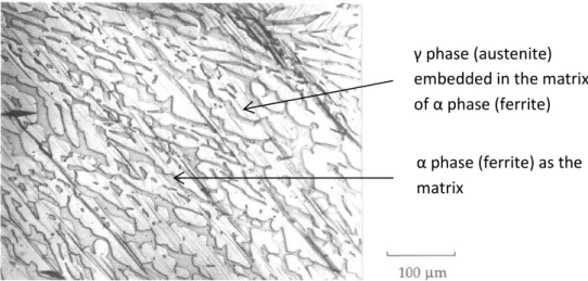
In this thesis we were interested in the austeno-ferritic steels, which are named duplex steel, when the phase proportion between austenite and ferrite is close to 50% - 50%. The duplex autenitic-ferritic stainless steel was discovered in the 1920s by J. Hochmann as a result of an error during intergranular corrosion test [Desestret 90]. The Fig. 1.2 shows typical microstructures of duplex steels [DeBold 89]. We can see the austenitic phase in the shape of “islands”, embedded in the ferritic matrix. τnce the stainless steel solidifies from melted state it transforms at first to a completely ferritic phase, then during cooling to room temperature, about half of the ferritic grains transforms to austenitic grains, forming a austeno-ferritic microstructure about 50% to 50% in volume fraction.
Figure 1.2 Microscopic image of duplex steel [DeBold 89].
In the table 1.1 the representative mechanical properties of ferritic, austenitic and duplex steels are summarized [El Bartali 07].
Stainless steel Yield strength
(MPa) strength Rm Tensile (MPa)
Elogation at
break A (%) modulus E Young’s (GPa) Hardness Hv (HB) Ferritic 250-400 300-600 18-25 220 190-220 Austenitic 200-250 570-900 50-60 200 210 Duplex Austenitic-ferritic 450-650 730-900 25-30 200 260-290
13
Generally, the ferritic steels have greater yield strength than the austenitic steels, but the ferritic steels are more brittle at low temperature [Lacombe 90, Davis 94]. On the other hand, the austenitic steels show an excellent corrosion resistance as well as a much higher ductility [Lacombe 90, Davis 94]. In duplex steels, ferrite enhances the yield strength level meanwhile the content of austenite improves their ductile behaviour. Therefore austenic-ferritic duplex steels combine good properties of both ferritic and austenitic phases.
Duplex stainless steels are often applied under corrosive and aggressive working conditions, as in the chemical or oil industry, where the mechanical parts are exposed to a corrosive environment or undergo cyclic loadings. The forged and hot-rolled duplex steel have been studied and presented in several works [Aubin 01, EL Bartali 07, Evrard 08, Le Joncour 11]. A number of studies on a casted duplex stainless steel used in the cooling system of a nuclear power plant have also been published [ψugat 00, M’ωirdi 01]. In the cooling system, these steels are subjected to a slow thermal aging at the working temperature of 320°C, which causes an embrittlement of the ferritic phase ferrite [Bonnet 90, Pumphrey 90]. It is well known that, at temperature lower than 475°C, the spinodal decomposition of ferrite occurs [Lacombe 90, Mateo 97, Park 02]. The transformation of ferrite is essentially caused by the spinodal decomposition leading to the formation of α phase (ωr-poor) and α’ phase (Cr-rich) in ferrite, as well as by the nucleation and the growing precipitation of an intermetallic phase rich in nickel, silicon and molybdenum. The rich in chromium α’ phase exhibits the same body centre cubic lattice structure as α phase (Fig. 1.1a) [Terada 08]. The presence of α’ phase results in the loss of several properties, such as ductility, toughness and corrosion resistance. The detail description of the embrittlement and hardening mechanism occurring during aging of the duplex steel is presented in Appendix 2.
1.1.1 Slip modes in duplex steel
One of the main objectives of this thesis is to study and deepen our knowledge of the plastic deformation occurring in polycrystalline materials. The plastic deformation of crystal materials mainly consists of slipping and twinning. In this thesis, we focus especially on the activation of slip systems and the interaction between slip systems in different phases. The slip mode in different crystal structures during plastic deformation is described in this section.
14
Several main structure parameters for crystal lattice of ferritic and austenitic phase are presented in table 1.2. The fcc structure of austenite allows the dislocations sliding along 4 planes of {111} family, in each of these planes there are 3 possible slip directions <011> (slip systems {111}<011> as shown in Fig 1.3a). In the bcc structure of ferritic phase, the dislocations slide along 3 different plane families, i.e. {011}, {112}, {123} and for all the 2 families of slip planes, their slip directions belong to the direction family <111> (slip systems {011}<111>, {112}<111> and {123}<111> as in Fig. 1.3b). Finally for each austenitic grain 12 slip system of {111}<011> and for each ferritic grain 48 slip systems belonging to {011}<111> and {112}<111> can be selected [Schmid 50].
Phase Ferrite Austenite
Structure bcc fcc
Lattice parameter (ambient
temperature ≈ 20°C ) 2.8664 Å 3.5770Å
Number of atoms per unit cell 2 4
Packing density 68% 74%
Slip planes {011}, {112}, {123} {111}
Slip directions <111> <011>
Atom density on slip plane ≈ 8γ% ≈ λ1%
Table 1.2 Summary of Main parameters of crystal lattice and slip systems for ferrite and austenite [Schmid 50, Person 67, El Bartali 07, Van 14].
Figure 1.3 Slip systems in fcc lattice (a) and in bcc lattice (b) [El Bartali 07, Van 14].
The mechanism of plastic deformation in the ferritic and austenitic phases has been studied in a number of works [Duval 92, Joly 92, Kruml 97, Bugat 00, Fréchard 06, El Bartali 07, El Bartali 08, Di Gioacchino 15]. The plastic deformation spreads more homogeneously in
15
austenite and a great number of slip lines can be observed over a large area (Fig 1.4) [Joly 92]. Meanwhile, the plastic deformation mode is relatively localized for ferrite, i.e. less slip lines concentrating in a smaller area can be found (cf. Fig. 1.5a) [Joly 92]. In Fig. 1.5b we can see continuous slip lines over several grains, crossing the phase boundaries and leading to a homogeneous deformation in both phases.
Figure 1.4 Optical micrograph on surface of a duplex alloy (Y4331) sample under tensile load at 20°C. Slip lines can be observed in austenite ( phase) [Joly 92].
Figure 1.5 (a) Surface of a duplex alloy (Y4331) sample under tensile load at 20°C studied by SEM method. Continuous slip lines between ferrite (α phase) and austenite ( phase) [Joly 92]. (b) Slip lines occurring in austenite ( phase) and in the vicinity of grain boundariein white frame) [El Bartali 07].
Using Scanning Electron Microscope (SEM) method for the sample surface during a fatigue test, it was observed that the slip systems in austenite were activated long before those in ferrite (Fig. 1.5a) [El Bartali 07]. This very early emergence of slip lines in austenite is considered as being coherent with the lower yield strength of this phase, compared with that
α
α phase (ferrite) as the matrix
γ phase (austenite) embedded in the matrix of α phase (ferrite)
α
(a) (b)
γ
16
of ferrite. It is also seen that the slip systems having high Schmid factors are activated in austenitic phase, however it is not always the case of glides in ferritic phase. The slip lines appear frequently in the vicinity of grain boundaries, and the dislocations tend to accumulate around the grain boundaries during plastic deformation due to the noncontinuity of slip lines (Fig. 1.5b).
Orientation relationship Expression Number of variants Kurjumov-Sachs { } ||{ } || 24 Nishijama-Wassermann { } ||{ } || or || 12
Table 1.3 Orientation relationships between slips in ferrite and austenite [Jonas 05].
The continuity of slip lines between phases is caused by some particular orientation relationships between the slip systems in ferrite and austenite, as summarized in table 1.3. Such orientation relationships enable the transfer of gliding from one phase to another. It should be emphasized that in the case of hot-rolled steel used in this present study, the recrystallization effect of material was not completed during rolling process and the later thermal treatment. Thus both phases are not bipercolated anymore and obey almost only the Kurjumov-Sachs relation [Kurjumov 30].
1.1.2 Ductile damage in duplex steels
The ductile damage process in duplex steels has been reported by several literatures. Verhaeghe et al. [Verhaeghe 96] reports that the fracture resulted by tensile load is roughtly perpendicular to the tensile axis. Plenty of linear streaks were observed occurring on the cleavage faces and forming the micro-cracks in shape of “fish bone”, which resulted from the emergence of slip plains localized in ferrite. EBSD analysis shows that microcracks initiate in the ferrite ether on slip plans with highest Schmid factor or at the austenite/ferrite boundaries and propagate along slip lines in ferritic grain [Alvarez-Armas 12]. Joly [Joly 92] noted the cleavage cracks initiated at the cutting edge between two twinned crystals in aged ferritic steel.
17
After the initiation, the most frequently observed ductile damage process at room temperature in duplex steels is the cleavage of ferrite combined with ductile fracture of austenite. The macroscopic cracks through austenite arise by coalescence of cavities formed from the micro-cracks engendered by brittle cleavage of ferrite, as illustrated in Fig. 1.6 [Le Roux 99].
Figure 1.6 Illustration of mechanism of ductile damage in aged duplex steels at room temperature [Le Roux 99].
1.1.3 Research status
The plastic deformation of polycrystalline materials have been already studied by our work team, abundant achievements have been made during these years. In this section, some representative results will be presented, on which is based the thesis work.
1.1.3.1 Elasto-plastic deformation of duplex steel
An interesting study concerning evolution of plastic deformation in the two phases of duplex steel was performed using EψSD method by Wroński et al. [Wroński 1β]. ψy investigating the evolution of IQ (image quality) factor, it was found that estimated deformed volume fraction is higher in the austenitic phase than in the ferritic phase. Moreover the
Load
Load
Load
Initiation of cleavages in ferrite
Formation of micro-cracks due to deformation of austenite
Coalescence of micro-cracks and fracture
18
changes of misorientations in both phases show that the austenitic grains (which build the “islands” of this phase in the initial sample) deformed more homogeneously than the ferritic grains (Fig. 1.7a). In the case of ferrite, changes in the internal substructure lead to significant segmentation inside grains thus the grain size decreased significantly (Fig. 1.7b).
(a) (b)
Figure 1.7 (a) Maps of low and high angle boundaries (misorientation angle between grains) for ferritic (alpha) and austenitic (gamma) phases. (b) Grain size for both phases for initial sample (INIT), medium deformation (MID DEF) and large deformation (LARGE DEF).
The mechanism of elasto-plastic deformation in duplex steel has been studied by [Jia 08, Le Joncour 10] and [ψaczmański 1θ] by neutron diffraction during “in-situ” tensile test. The evolutions of interplanar spacing of each {hkl} reflection measured in the direction of applied force were drawn in function of the calibrated stress, as illustrated in Fig.1.8 [Le Joncour 11]. Three elasto-plastic deformation steps and the initiation of damage process can be identified from these curves. During the step Eα, from 0 to βη0MPa, both ferrite (alpha) and austenite (gamma) are deformed elastically, and a linear dependence of lattice strains in function of the applied stress can be observed for both phases. The slopes of these plots are related to the so called X-ray Elastic Constant (XEC) of each {hkl} reflection.
19 Figure 1.8 Complete evolution curves of micro-strain until initiation of damage process for ferrite (a) and for austenite (b) [Le Joncour 11].
The step EαP corresponds to the beginning of plastic deformation of austenite, while the ferrite continues elastic deformation. We can see the slopes of all curves for {hkl} reflections in austenite declined. Simultaneously, the slopes of {hkl} reflections in ferrite rose, indicating that ferrite received a part of stress released by austenite.
During the third step Pα, , both phases underwent plastic deformation, but the increase of interplanar spacings in the ferrite was slower than in the austenite, which means that the austenite retook a part of load from the plastically deformed ferrite. It can be concluded that the work hardening rate of the austenitic phase is higher comparing with the ferritic phase. The stage D show the initiation of ductile damage, which will be discussed in the next section.
From the previous study performed by Le Joncour et al. [Le Joncour 10], we can see that different elasto-plastic behaviours of the austenitic and ferritic phases are intrinsically related to their crystal structures as well as the slip modes operating in the crystal lattice.
Diffraction mode Neutron Synchrotron
Material Quenched
UR45N Aged UR45N
Quenched
UR52N Aged UR45N
Load type Tension Tension Compression Tension Tension
Ferrite
CRSS (MPa) 220 350 360 290 410
Austenite
CRSS (MPa) 140 140 120 180 150
Table 1.4 Initial CRSS values for ferrite and austenite determined by different experimental methods on different grades of duplex steels [ψaczmański 1θ].
20
The activation of slip systems for each phase has been also investigated in the previous work by [ψaczmański 1θ], where the neutron diffraction and synchrotron coupled with in-situ tensile or compression tests were employed on samples of different grades of duplex steels. The predictions with self-consistent model compared with experimental data were carried out to determine the initial Critical Resolved Shear Stress (CRSS) for each phase. The determined values of CRSS are given in table 1.4.
It can be noted that the initial CRSS of ferrite are always higher than that of austenite for all studied duplex steels. This leads to considerably lower yield stress of austenite compared with that of ferrite, and agrees with the above presented experimental observation that slip lines were initiated firstly in the austenitic grains.
1.1.3.2 Ductile damage process duplex steel
As at the end of phase strain evolution curves (Fig. 1.7a), material softening is observed in ferrite after threshold D. It is very interesting to note that the interplanar spacings measured using {hkl} reflections significantly decreased in the ferrite. Meanwhile, the austenite took the load released from the ferritic phase. This phenomenon could indicate an initiation of damage process occurs in the ferritic phase, confirming the relatively lower ductility of the ferrite compared to that of the austenite (table 1.1).
(a) (b)
Figure 1.9 SEM picture for initiation of damage, a crack occurred along slip plane within ferretic phase (a); interfacial cracks occurred on the boundaries between two phases (b) [Le Joncour 11].
The initiation of ductile damage process has been studied by Le Joncour and Wronski et al. [Le Joncour 11]. Some microscopic observations confirm the initiation of damage in the ferritic phase. As illustrated in Fig. 1.9a [Le Joncour 10], a crack was observe along the slip line inside ferritic phase, which suggests the cleavage initiates in ferrite; and cracks appeared on the boundaries between two phases (Fig. 1.9b).
21
[Le Joncour 11] also proposed an assumption for damage process based on the experimental observation, the supposed process of ductile damage is shown by Fig.1.6. This assumption considers that the ductile damage occurs only after the plastification of both phases, and inclusions are supposed occurring homogeneously in both phases.
Figure 1.10 Proposition for the process of ductile damage in duplex steels [Le Joncour 11].
1. Both phases are plastified and the damage process is considered beginning only after the plastification of both phases.
2. The interfacial decohesion cracks occurred close to the fracture surface but also observed in the area less deformed. Thus, this type of cracks can be considered as the first appearance of damage (Fig. 1.7 b).
3. The cleavages or cracks along the slip lines in ferrite (Fig. 1.9 a) lead to the relaxation of the ferritic phase (observed by neutron diffraction, Fig. 1.7 a).
4. The inner-ferrite cracks and the interfacial decohesion cracks merge together under the further imposed external load.
5. The ductile fracture occurs by coalescence of all different cracks inside material. The material is finally damaged.
The studies on duplex steel in present thesis are carried out following the current research findings, mainly focus on the initiation of damage process during large deformation stage.
Inclusion Austenite Ferrite Cleavage or crack
22
1.1.4 Characterisation of studied duplex steels
The samples prepared for in situ tensile tests are made of two grades of duplex steels, UR45N and UR52N. Both raw alloys are continuously casted and then hot rolled. Subsequently, three experimental specimens are prepared by different thermal treatments from these two materials. UR52N and a portion of UR45N alloys are heat treated at 1050°C and then quenched in water, to avoid precipitation of secondary phases. Another portion of UR45N alloy is subjected to a thermal treatment at 400°C for 1000h in order to age the material. The chemical compositions of the studied duplex steels are given in table 1.5.
C Mn Cr Ni Mo Cu S N
UR45N 0.015 1.6 22.4 5.4 2.9 0.12 0.001 0.17 UR52N 0.016 1.02 25.18 6.46 3.78 1.61 0.0005 0.251
Table 1.5 Chemical compositions of duplex stainless steel UR45N and UR52N: mass-percent (Fe= balance).
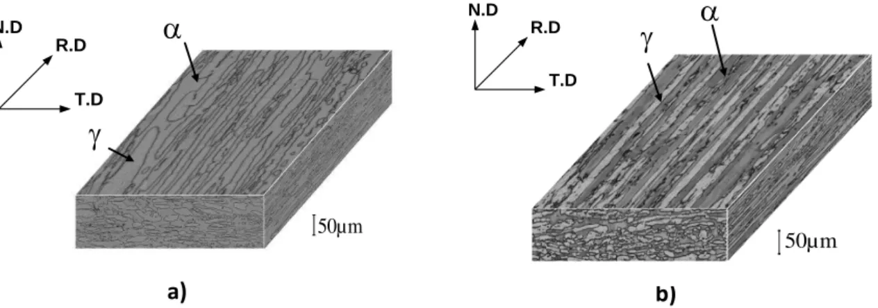
The microstructure of the studied material is constituted of ferritic phase and austenitic phase in approximately equal volume proportions (50% austenite to 50% ferrite). As shown in the Fig. 1.11 a and b [Dakhlaoui 07], the microstructure of both materials consists of austenitic ( phase) ‘island’ elongated along the rolling direction and evenly embedded in the ferritic (α phase) matrix.
Figure 1.11 Three dimensional microstructure of duplex stainless steel (a) UR45N, (b) UR52N [Dakhlaoui 07].
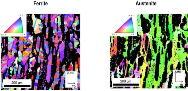
The EBSD (Electron Backscatter Diffraction) orientation maps [Schwartz 09] made for UR45N steel (Fig. 1.12 [Le Joncour 10]) show that austenite islands are divided into smaller crystallites with different orientations, meanwhile the grains of ferritic phase possess nearly the same crystal orientation resulting from the rolling process.
a) b) 50µm
T.D R.D N.D b)
50µm T.D R.D N.D23
Ferrite Austenite
Figure 1.12 Microstructure of the UR45N duplex stainless steel determined by EBSD method. Orientations of austenitic and ferritic grains are shown in the selected phase by colors while the grains of the unselected phase are black [Le Joncour 10].
Subsequently, the experimental pole figures {110}, {200}, {211} and {111}, {200}, {220} are measured respectively for the ferrite and the austenite, using Cr radiation X-ray on Seifert four circles diffractometer. The Orientation Distribution Function (ODF) [Bunge 82] is determined independently from the measured experimental pole figures for each phase of both materials (UR52N and UR45N), using the WIMV algorithm [Kallend 90]. Significant anisotropy of grain orientations is found in both phases, and especially pronounced texture is obtained for ferrite, as shown in Fig. 1.13.
Phase C11 (GPa) C12 (GPa) C44 (GPa)
Austenite 198 125 122
Ferrite 231 134 116
Table 1.6 Single-crystal elasticity constants of austenite and ferrite [Simons 71, Inal 99].
The crystallographic textures (Fig.1.13) and typical single crystal elastic constants (given in table 1.6) for ferrite and austenite are used in calculations of the X-ray Elastic Constants (XEC) obtained by the Eshelby-Kröner approach [Eshelby 57; Kröner 61], as proposed by ψaczmański et al. [ψaczmański 0γ] and Wroński et al. [Wroński 07].
24
(a) (b)
(c) (d)
Figure 1.13 Orientation distribution function (ODF) for austenitic phase and ferritic phase of duplex steel UR45N (a and b) as well as of UR52N (c and d), determined by X-ray diffraction (Cr radiation). The sections through Euler space with the step of η° along the φ2 axis are presented for (a) austenitic and (b) ferritic phases in UR45N sample. The orientation of the sample is: x1ǁTD (transverse direction),x2ǁND (normal direction) and x3ǁRD (rolling direction).
25
1.2 D
escriptions of two-phase titanium
Two-phase titanium alloy is another material engaged in the studies of this thesis. The microstructure has also a strong influence in the mechanical behaviour of titanium alloys, especially the size and arrangement of the hexagonal α titanium and body-centreed cubic titanium are of prime importance. Lamellar microstructures are originated from cooling out of titanium field (Fig. 1.14a), and equiaxed microstructures results from recrystallization process. The final microstructure of titanium can either individually exhibits a fine or coarse distribution of grains or both type of grains can be present in a bimodal microstructures (Fig. 1.14b). In the bimodal microstructure, two morphologies can be identified for α titanium as indicated in Fig. 1.14b, i.e. the globular primary α phase ( ), and the acicular secondary α phase ( ).
Lamellar (a) Bimodal (b)
Figure 1.14 Typical microstructures of two-phase titanium alloys: (a) lamellar α-titanium embedded in the matrix of -titanium; (b) bi-modal microstructure, granular primary α-titanium ( and acicular secondary α-titanium ( embedded in matrix of -titanium [Peters 03].
Compared with equiaxed microstructures, lamellar structure usually shows better creep behaviour due to their coarser structure, meaning a lower volume fraction of phase boundaries. On the other hand, equiaxed and bimodal microstructures show superior fatigue properties due to their fine microstructures.
26
1.2.1 Elasto-plastic deformation in two-phase titanium
The crystal structures of α and titanium are respectively hcp and bcc (cf. unit cells shown in Fig. 1.1 a and c). The main parameters of the lattice for each phase are presented in table 1.7 [Schmid 50, Person 67, Peters 03, Lütjering 07].
The titanium alloys exhibit pronounced anisotropic behaviour, especially concerning their elasto-plastic properties, due to the presence of hexagonal α titanium and pronounced textures. The monocrystal elastic constants of α-titanium varies significantly between 145GPa in the direction vertical to the basal plane and 100GPa in the direction parallel to this plane. [Lütjering 07]. In general, commercial titanium alloys have lower modulus of elasticity E than α and α + titanium alloys. The typical E values of commercial phase alloys are in the range of 70 - 90GPa for the as-quenched condition and 100 – 105GPa for the annealed condition, while E is equal approximately 11ηGPa for commercial α + alloys [ψoyer λ4].
Phase α titanium Β titanium
Structure hcp bcc Lattice parameter a=2.8664 Å c=4.68 Å (measured at ≈ β0°ω ) 3.32Å (measured at 900°C ) c/a ratio 1.587
Number of atoms per unit cell 6 2
Packing density 74% 68%
Slip planes {0001}, {0110},
{0111}, {11 } {110}, {112}, {123}
Slip directions <1120>, <1123> <111>
Atom density of slip plane ≈ λ1% ≈ 8γ%
Table 1. 7 Summary of main parameters of crystal lattice and slip systems for ferrite and austenite [Schmid 50, Person 67, Peters 03, Lütjering 07].
The deformation mechanisms of titanium have been studied over the past decades. Generally, the processes of plastic deformation and of diffusion are strongly related to the crystal structures. In this thesis, we mainly focus on the slip systems in the lattice of titanium and their activation mechanism. Fig. 1.15 [Greenfield 72] shows the continuity of slip lines between α titanium and titanium and this effect is related to the crystal structures of each phase. As illustrated in Fig. 1.16, α titanium exhibits a hexagonal close-packed crystal structure (hcp). ψecause of the bcc structure of titanium, the mechanism of slip systems
27
activation and slip modes in this phase can be referred to the above described slip systems operating in ferrite.
Figure 1.15 Slip lines occurred on lamellar intergranular α platelets in matrix [Greenfield 7β].
The slip planes and slip directions in hcp structure are indicated in Fig 1.16 and summarized in table 1.8 [Patrudge 67, Yoo 81]. The three slip planes (the densely packed planes) are indicated in this figure, i.e. the {0001} plane with the highest density, called basal plane; the family of {0110} planes, called prismatic planes and the family of {0111} and {1122} planes, respectively called first order and second order pyramidal planes. The three close-packed directions <1120> along axes a1, a2 and a3 are the main slip directions (see Fig.1.16).
Figure 1.16 Illustration of hcp structure and the slip systems in α titanium [Balasubramanian 02].
(1) (2) (3)
(5)
{̅ }
28
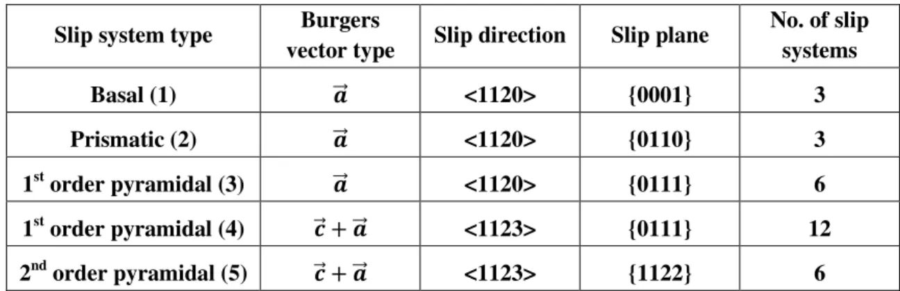
Generally, for an hcp crystal, several different deformation modes can be activated during its plastic deformation, such as twinning and gliding process. In this thesis, we mainly discuss the gliding process involving different slip systems of two types. The first type is <a> slip system with an a⃗ ψurger’s vector <11β0>, which can be found on basal plane {0001}, prismatic planes {01 0} and first-order pyramidal planes {0111}. The second type is <c+a> slip system with c + a⃗ ψurger’s vector <11 3>, which can be observed on the first {01 } and second {1122} pyramidal planes.
The plane families {0001}, {0110} and {0111} contain a⃗ type of Burgers vector [Burgers 34, Burgers 39], and these three different slip plane families together with the possible slip direction family <11 0> generate 12 slip systems (table 1.8). The dislocations with Burgers vectors type c + a⃗ have also been observed in several studies by Transmission Electron Microscope (TEM) [Paton 73, Jones 81]. In this experimental the load was applied in the direction parallel to c vector, thus neither slip system with a⃗ nor c Burgers vectors can be activated, because the Schmid factors [Schmid 50] for both potential slip directions were equal to zero. However, the angle between the planes {1122} containing c + a⃗ Burgers vectors and the c axis is close to 45°, which leads to the highest Schmid factor in a hcp lattice. This is the reason why the most likely activated slip system in α titanium is the so called βnd order pyramidal system <1123>{1122}, shown in the fifth one in table 1.8 [Partridge 67, Yoo 81, Balasubramanian 02]. Another possible slip plane containing dislocations with c + a⃗ are the prismatic {0111} planes, which together with <1123> directions generate the 1st order pyramidal systems <1123>{0111}, shown in table 1.8. The latter family of slip systems is frequently taken into account in elasto-plastic deformation model (cf. references in the caption of table 1.8).
Slip system type Burgers
vector type Slip direction Slip plane
No. of slip systems Basal (1) �⃗⃗ <1120> {0001} 3 Prismatic (2) �⃗⃗ <1120> {0110} 3 1st order pyramidal (3) �⃗⃗ <1120> {0111} 6 1st order pyramidal (4) ⃗ + �⃗⃗ <1123> {0111} 12 2nd order pyramidal (5) ⃗ + �⃗⃗ <1123> {1122} 6
Table 1.8 Summary of slip systems in hcp structure, the number of slip system type corresponding to that noted in Fig. 1.16[Partridge 67, Yoo 81, Balasubramanian 02].
29
According to several previous studies [Patridge 67, Bridier 05, Raabe 07, Wang 10, Beyerlein 10] on titanium alloys, and as illustrated in the work of [Bridier 05], the basal and prismatic slip systems have been shown as the main slipping modes for α phase in Ti-6Al-4V titanium alloy (cf. Fig. 1.17). Only a few 1st order pyramidal slip systems were observed in as a deviated gliding. In Fig. 1.17 we can see that the slip lines occurred in phase during the tensile test were mostly related to prismatic <1120>{0110} and basal <11 0>{0001} slip systems.
Figure 1.17 Identification of slip systems in α titanium: (a) microstructure before tensile test (arrow indicates tensile direction); (b) corresponding EBSD maps with grains orientation; (c) identification of slip lines at the beginning of plastic deformation of sample; (d) identification of slip lines before fracture of sample [Bridier 05].
The histogram in Fig. 1.18 shows distribution and activation of slip systems at different stress levels, histogram bars represent the occurring frequency of basal or prismatic slip systems in deformed . It clearly presents that the basal slip systems more likely tend to be activated than prismatic systems. Moreover, according to the experimental observation, the coexisting slip systems can be possibly either both prismatic systems and prismatic and basal systems in the same time.
(c) (d)
(b) (a)
30 Figure 1.18 Frequency of activated slip systems at different stress stages and their natures [Bridier 05].
χccording to ψridier’s work [Bridier 05], the prismatic <a> slip system is the most possibly activated slip system in α titanium at room temperature. And according to [Bridier 08], the predominance of slip along basal and prismatic planes is confirmed. However, by increasing the concentration of α stabilizer elements, which decrease the atomic spacing on basal plane [Raabe 07], the basal <a> slip system become easier to active. On the other hand, several previous works [Zambaldi 12, Benmhenni 13, Barkia 15, Gloaguen 15] show that the prismatic <a> slip system is the most easily activated system during plastic deformation process in α phase (see table 1.9, the values of critical shear stress for P<a> slip system are always the lowest). The presented CRSS values have been evaluated from a combination of experimental observations and micromechanical models.
CRSS values (MPa) of slip system in α titanium Slip
systems Indices Ref. (1) Ref. (2) Ref. (3) from (4)
P <a> { } 36 150 92 120
B <a> { } 252 349 105 182
1 <a> { } 144 - 145 149
1 <c+a> { } 288 1107 190 241
2 <c+a> { } 216 - - -
P <a>: a type prismatic slip system B <a>: a type basal slip system
1 <a>: a type 1st order pyramidal slip system 1 <c+a>: c+a type 1st order pyramidal slip system 2 <c+a>: c+a type 2nd order pyramidal slip system
(1): [Benmhenni 13] (2): [Zambaldi 12] (3): [Gloaguen 15] (4): [Barkia 15]
Table 1.9 CRSS for various possible slip systems in titanium and its alloys, determined by several authors using a combination of experimental observations and micromechanical models.
31
Analysing the available data concerning modelling of elasto-plastic deformation as well as the experimental data we can find different values of ωRSS for slip systems activated in α titanium. However, a great difference exists in the CRSS values for the same slip system, as reported in table 1.9. From these ambiguous results we are not able establish confirmable ranges for the CRSS of each slip system. Therefore, one of the main topics of this thesis is to determine the values of ωRSS for slip systems in two phase titanium alloy consisting of α and
phases.
Additionally, in two-phase titanium, the and phases usually obey a classical Burgers orientation relationship [Burgers 34], i.e. { } ||{ } and < > || < >
[Bhattacharyya 03, Jun 16], and a low energy, semi-coherent interface exists between the phases [Furuhara 95]. At the beginning of plastic deformation, dislocations tends to penetrate the semi-coherent interphase boundaries [Suri 99], then the coherency of interfaces is reduced due to the interaction between boundaries and lattice dislocations [Zhereblsov 10].
1.2.2 Ductile damage in two-phase titanium
χs mentioned above, the α titanium exhibits an hcp structure, which is able to lead to a partially different ductile damage process compared with duplex steels. It has been observed that during ductile damage in two-phase titanium, the micro-cracks were nucleated on the interphase boundaries [Greenfield 72]. Generally, the α titanium is considered being softer than titanium. The difference between the elaso-plastic behaviors of the two phases creates plastic strain incompatibilities at the α/ interfaces [Helbert λθ]. In Thompson and Williams’s study [Thompson 77], no evident particle nucleation or void have been found on the fractured surface of two-phase titanium alloys Ti-2Al and Ti-6Al-4V. Therefore, other possibilities should be taken into consideration, including twin-matrix interfaces, vacancy clusters, grain boundaries-slip band intersections and slip band-slip band intersections [Helbert 96]. In the studied Ti alloys, the local stresses can be higher in the hexagonal lattice compared with cubic lattice (bcc), due to limited capacity for their relaxation at slip bands intersections. These higher local stresses could result in dislocation coalescence [Stroh 57], which in turn could lead to the generation of micro-cracks.
32
(a) (b)
(c) (d)
Figure 1.19 Indicatied by red circles (a) void nucleation and growth at an equiaxed α- interphases interface; (b) nucleation of micro-cracks at grain boundary in lamellar α; (c) Micro-crack growth along
grain boundary; (d) crack propagation in fracture section [Greenfield 7β].
In Greenfield’s work [Greefield 7β], the void formation occurring at equiaxed α- interphases after uniaxial tensile test was observed (Fig. 1.19). It was found that the number of micro-cracks increased with the increasing level of applied stress triaxiality in the specimen. Meanwhile, greater void nucleation occurred in the early stage of deformation in samples with larger α particle size. In the lamellar structure of α titanium (Fig. 1.14a), the micro-cracks are formed only at the grain boundaries of α interfaces (Fig. 1.19), and the void nucleation rate increases generally when the grain boundary thickness increases.
In addition, a mechanism involving a pile-up of dislocations in α titanium leads to formation of cracks, which are later converted into a plastic crack. According to [Greenfield 7β], void started at α- interface, then it grown extensively into the phase. This mechanism, which breaks down the compatibility between α- interfaces and leads to the nucleation of micro-cracks, should be taken also into account in the description of the damage process
33
occurring in two phase Ti alloys (Fig. 1.19c). During growth the micro-cracks tended to move around an α particle rather than to break it (Fig. 1.19d). The void grown linearly with strain and occurred preferentially at grain boundary. The growth rate of micro-cracks increased with increasing size of grain, and the growth of cracks occurred due to local plastic flow at the tip of the void, rather than due to coalescence of smaller voids. Finally when a critical void length-stress relationship was reached, unstable fracture took place.
Using EBSD mapping technique, the crack formation planes have been identified by [Bridier 08]. As illustrated by Fig. 1.20, the crack formation is observed along prismatic (Fig. 1.20a) and basal (Fig. 1.20b) planes. Most prismatic cracks are remained to the primary nodule and parallel to straight and regularly spaced slip bands. In contrary, the basal cracks appear ealier and have propagated through the surrounding microstructure under the same external load, indicating the fatal cracks more likely to form on the basal plane.
Figure 1.20 Identification of slip planes along which cracks formed.Crack formation on Prismatic plane (a), on Basal plane (b).
1.2.3 Characterisation of experimental TIMETAL-18 alloy
The TIMETAL-18 (mentioned as Ti-18 thereafter) is a high strength near-beta phase titanium alloy, with a nominal composition Ti-5.5Al-5V-5Mo-2.4Cr-0.75Fe-0.15O (in weight percent), produced by TIMET (Valley Creek Blvd. USA).
The studied material was received as a quarter of ingot with a diameter of 250 mm. The as-received ingot was prepared by vacuum arc remelting, then by forging and rolling below the beta transformation temperature (beta transus). After that the material was processed by solution heat treating at a subtransus temperature (1089K) for 2 hours, and then air cooled.
35
A HITACHI SU-8030 Scanning Electron Microscope (SEM) was employed to perform the microscopic observation [Li 15]. A typical bimodal structure of titanium alloys (cf. section 1.) can be observed, as shown in Fig. 1.22 and Fig. 1.23. At low magnification level, the characteristic microstructure of Ti-18 consists of uniformly spread globular primary α-titanium nodules embedded in -phase matrix. The shape of nodules is not significantly different between two observed sections (axial and radial). The images obtained with higher magnification are presented in Fig. 1.22 b and Fig. 1.23 b, where lamellar secondary phase is seen. The lamellas were transformed form -titanium during heat-treatment process.
(a) (b)
Figure 1.22 SEM images of the microstructure of Ti-18 on ingot radial cross section, (a) low magnification image (β,000x) [Li 1η], showing globular primary α-titanium nodules embedded in the transformed -titanium matrix; (b) high magnification image (10,000x), showing a typical bimodal microstructure, lamellar secondary α-titanium precipitated inside the transformed -titanium matrix during precipitation hardening process.
(a) (b)
Figure 1.23 SEM images of the microstructure of Ti-18 on ingot axial section, similar bimodal structure as observed on radial section: (a) low magnification image (2,000x) [Li 15]; (b) high magnification image (10,000x).
36
The estimation of volume fraction for each phase was carried out on both radial and axial cross sections by image processing technique in which the microscopic pictures were converted into binary images (black and white). The detailed estimation steps are described in Appendix 18. Finally, the previous study by [Lebrun 14] shows the volume fraction of α titanium varies between 44% and 52% according to the conditions of heat treatment (see Appendix 18), which agrees with the estimation results (table 1.1β). The volume fraction of α titanium is finally determined about 45%. And this volume fraction will be further used in the prediction of elasto-plastic behavior of Ti-18 by EPSC model.
Section Surface fraction Surface fraction in
matrix
Total surface fraction of titanium
Radial 18.61% 34.96% 47.06%
Axial 24.49% 23.86% 42.5%
Table 1.12 Fractions of α titanium calculated from both the radial and axial cross section.
To characterize crystallographic texture in both phases of the studied Ti alloy, two sets of pole figures, i.e. {0001}, { }, { }, { } and {011}, {002}, {112} were measured respectively for α and titanium. The measurements were done on the surface perpendicular to axial direction. The similar character of {0001}-α and {011}- pole figures (presented in Fig. 1.24a) confirms the Burgers relationship occurring between orientations of the lattices for both phases, i.e., { } ||{ } [Newkirk 53]. Moreover, both textures exhibit nearly
orthorhombic symmetry. The Orientation Distribution Functions is given in Fig. 1.24b, which are determined for each phase independently from all sets of pole figures, using the WIMV method implemented in the popLA computer package [Kallend 90].
![Table 1.2 Summary of Main parameters of crystal lattice and slip systems for ferrite and austenite [Schmid 50, Person 67, El Bartali 07, Van 14]](https://thumb-eu.123doks.com/thumbv2/123doknet/14528473.723214/23.892.168.727.414.622/summary-parameters-crystal-lattice-systems-ferrite-austenite-bartali.webp)
![Figure 1.6 Illustration of mechanism of ductile damage in aged duplex steels at room temperature [Le Roux 99]](https://thumb-eu.123doks.com/thumbv2/123doknet/14528473.723214/26.892.157.775.290.716/figure-illustration-mechanism-ductile-damage-duplex-steels-temperature.webp)
![Table 1.4 Initial CRSS values for ferrite and austenite determined by different experimental methods on different grades of duplex steels [ψaczmański 1θ]](https://thumb-eu.123doks.com/thumbv2/123doknet/14528473.723214/28.892.113.781.108.393/initial-ferrite-austenite-determined-different-experimental-different-ψaczmański.webp)
![Figure 1.9 SEM picture for initiation of damage, a crack occurred along slip plane within ferretic phase (a); interfacial cracks occurred on the boundaries between two phases (b) [Le Joncour 11]](https://thumb-eu.123doks.com/thumbv2/123doknet/14528473.723214/29.892.159.743.708.935/figure-initiation-occurred-ferretic-interfacial-occurred-boundaries-joncour.webp)
![Figure 1.10 Proposition for the process of ductile damage in duplex steels [Le Joncour 11]](https://thumb-eu.123doks.com/thumbv2/123doknet/14528473.723214/30.892.147.760.248.606/figure-proposition-process-ductile-damage-duplex-steels-joncour.webp)
![Figure 1.16 Illustration of hcp structure and the slip systems in α titanium [ Balasubramanian 02]](https://thumb-eu.123doks.com/thumbv2/123doknet/14528473.723214/36.892.167.742.684.1102/figure-illustration-hcp-structure-slip-systems-titanium-balasubramanian.webp)