Publisher’s version / Version de l'éditeur:
Vous avez des questions? Nous pouvons vous aider. Pour communiquer directement avec un auteur, consultez la première page de la revue dans laquelle son article a été publié afin de trouver ses coordonnées. Si vous n’arrivez pas à les repérer, communiquez avec nous à PublicationsArchive-ArchivesPublications@nrc-cnrc.gc.ca.
Questions? Contact the NRC Publications Archive team at
PublicationsArchive-ArchivesPublications@nrc-cnrc.gc.ca. If you wish to email the authors directly, please see the first page of the publication for their contact information.
https://publications-cnrc.canada.ca/fra/droits
L’accès à ce site Web et l’utilisation de son contenu sont assujettis aux conditions présentées dans le site LISEZ CES CONDITIONS ATTENTIVEMENT AVANT D’UTILISER CE SITE WEB.
Research Report (National Research Council of Canada. Institute for Research in
Construction), 2006-01-01
READ THESE TERMS AND CONDITIONS CAREFULLY BEFORE USING THIS WEBSITE. https://nrc-publications.canada.ca/eng/copyright
NRC Publications Archive Record / Notice des Archives des publications du CNRC :
https://nrc-publications.canada.ca/eng/view/object/?id=a461b5df-5b18-4b20-8da4-36137ef70876 https://publications-cnrc.canada.ca/fra/voir/objet/?id=a461b5df-5b18-4b20-8da4-36137ef70876
Archives des publications du CNRC
For the publisher’s version, please access the DOI link below./ Pour consulter la version de l’éditeur, utilisez le lien DOI ci-dessous.
https://doi.org/10.4224/20377352
Access and use of this website and the material on it are subject to the Terms and Conditions set forth at
Intermediate-Scale Furnace: A New Fire Resistance Test Facility at the
National Research Council Canada
Intermediate-scale Furnace: A
New Fire Resistance Test Facility
at the National Research Council
Canada
Research Report #213
Date of Issue: January 2006
Authors: M.A. Sultan, Y.P. Séguin , J.C. Latour, P.
Leroux and J.P. Henrie
Published by
Institute for Research in Construction National Research Council Canada Ottawa, Canada
Intermediate-scale Furnace: A New Fire Resistance Test Facility
at the National Research Council Canada
by
M.A. Sultan, Y.P. Séguin, J. Latour, P. Leroux and J. Henrie
ABSTRACT
A new non-standard intermediate-scale fire resistance test furnace facility was commissioned at the National Research Council of Canada to test reduce-scale building elements such as walls, floors, beams and slabs with and without applying load. This was developed to complement the long existing standard full-scale wall and floor furnace fire resistance test facilities at the National Research Council. This new furnace helps to reduce time and costs associated with testing building elements and it can be used to examine assembly design parameters prior to testing an assembly in a full-scale furnace. Although this non-standard furnace facility is not intended to replace tests in the full-scale furnaces, it can be used as an intermediate step to reduce the number of full-scale tests needed during the design and development phases of an assembly. This facility has also proven to be a very versatile tool in a several major NRC projects as it allows the researchers and clients to perform – inexpensively and quickly – parametric comparisons of building elements of different design parameters, identifying the most promising solutions, which can then be tested at full-scale to verify their acceptability. This furnace can be run using the time-temperature curves specified by the CAN/ULC-S101, ASTM E119 and ISO 834 standards or by using a custom designed time-temperature curve.
Intermediate-scale Furnace: A New Fire Resistance Test Facility
at the National Research Council Canada
by
M.A. Sultan, Y.P. Séguin, J. Latour, P. Leroux and J. Henrie
1.0 INTRODUCTION
Increasingly fire-rated floor and wall assemblies made of new materials and using non-traditional construction methods are being used in buildings today. To determine the fire-resistance of such assemblies, full-scale tests are being used to help engineers, architects and codes officials make cost-effective design decisions. As these tests are expensive and time consuming, IRC’s Fire Research Program is working towards developing a simpler and less expensive approach.
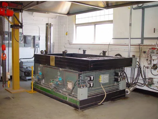
IRC recently constructed an intermediate-scale furnace, 1.33 m by 1.94 m (4 by 6 feet) (see figure 1), that can be used for preliminary testing of wall and floor
assemblies as well as concrete beams and slabs (both structurally loaded and unloaded). While the development of a non-standard intermediate-scale furnace test method is not intended to replace the full-scale method, it offers an opportunity to reduce the number of full-scale tests needed during the design and development phase of an assembly. This could result in significant savings for practitioners, as the cost of an intermediate-scale test is about 33% that of a full-scale test.
In the meantime, the intermediate-scale furnace has already demonstrated its usefulness as a screening tool in two major IRC projects: one examining the effect of specific design parameters, such as the application of insulation materials in the floor
cavity, on the fire resistance of lightweight floor assemblies, and another evaluating the effects of insulation type and thickness on the behaviour of concrete slabs strengthened with fibre-reinforced polymers (FRPs) in fires. The intermediate-scale facility allows the clients and researchers to perform—inexpensively and quickly—parametric comparisons of assemblies, identifying the most promising solutions, which can then be tested at full scale to verify their performance.
2.0 DESCRIPTION OF FURNACE
The test furnace is designed to produce conditions under which floor, wall, beam and slab building elements are exposed to heat during a test in accordance with either a time-temperature curve specified in the CAN/ULC-S101 (1), ASTM (2) or ISO 834 (3) fire resistance standards, or by using a custom designed fire development profile. The furnace is equipped with two loading systems: one for a horizontal configuration with maximum superimposed load of 218.2 kN (floor, beam and slab) and other for vertical configuration with maximum superimposed load of 117.7 kN (wall) to test building elements, if required, with superimposed live loads. The furnace consists of a steel framework with its furnace chamber lined with two layers of insulating firebricks. This furnace can be rotated around on a hinge point with the help of a hydraulic piston mounted at the base of the furnace to form either a vertical furnace (wall furnace configuration, see Figure 2) or to form a horizontal furnace (floor furnace configuration, see figure 1). The furnace in its vertical position is shown in Figure 2, for a wall building element required to be fire tested with a superimposed load. The Furnace in its
horizontal position is shown in figure 1, for floor, slab, or beam building element required to be tested with a superimposed load.
Figure 1 Intermediate-scale Furnace in the Horizontal Position (Floor Furnace)
Figure 2 Intermediate-scale Furnace in the Vertical Position (Wall Furnace)
The furnace is equipped with four Eclipse TM (4) ThermJet * 73 kW propane
nozzle-mix medium velocity burners for a total of 292 kW. Each burner is designed for direct spark ignition eliminating the need for pilot lines. An Eclipse TM multiple ThermJet burner control
system ensures the proper firing sequence and full safety through multiple interlock
sensors and solenoid valves. The furnace works on a fixed combustion air system with gas modulated to achieve furnace temperatures according to the required time-temperature profile. The furnace temperature is controlled by a Honeywell TM (5) digital PID controller
that can be programmed to follow the standard time-temperature curve for control of fire tests as described in the standards: CAN/ULC-S101 –04 (1) “Standard Methods of Fire Endurance Tests for Building Construction and Materials”, ASTM E119 (2) “Standard Test Methods for Fire Tests of Building Construction and Materials”, and ISO 834 (3) “Fire-Resistance Tests – Elements of Building Construction. It can also be programmed to follow a non-standard time-temperature curve if need arises. Four dual element Chromel-Alumel K-type thermocouple probes measure the temperature inside the furnace chamber; a fifth thermocouple probe is installed inside the furnace for safety purposes to monitor an upper temperature limit. The average temperature from one set of the dual element
thermocouples is used as feedback to the PID controller; the other set is fed back to the data acquisition system for recording. A Honeywell TM (6) ModutrolTM motor accepts a 4-20
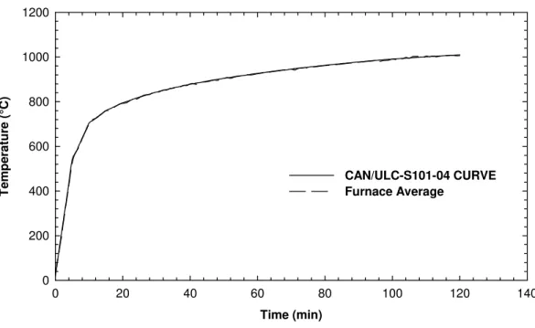
ma signal from the PID controller to position a gas modulation butterfly valve. The motor is fitted with auxiliary switches actuated by adjustable cams. Switches are used to indicate the “low fire” position to the Eclipse TM burner controller. Figure 4 indicates the extent to which
this furnace can be controlled to closely follow, for example, the time-temperature curve specified by the CAN/ULC-S101 standard.
* Certain commercial products are identified in this report in order to adequately specify the experimental procedure. In no case does such identification imply recommendations or endorsement by the National Research Council, nor does it imply that the product or material identified is the best available for the purpose.
Figure 3 Intermediate-scale Furnace Chamber
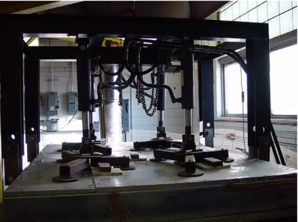
Two separate sets of hydraulic jack assemblies apply loading in either the horizontal or vertical configuration. In the horizontal position, mainly used to test floor assemblies, four hydraulic jacks, as shown in Figure 5, are capable of uniformly apply a maximum load of 218.2 kN. In the vertical position, a maximum load of 117.8 kN can be applied from six hydraulic pistons connected to a horizontal loading beam at the bottom of the furnace.
Time (min) 0 20 40 60 80 100 120 140 T em p e rat ur e ( °C) 0 200 400 600 800 1000 1200 CAN/ULC-S101-04 CURVE Furnace Average
Figure 4 Average Furnace Temperature (Measured vs Standard Curve)
This furnace, contrary to the full-size furnaces, does not have a furnace chamber exhaust fan. One main blower supplies combustion air to the four burners. A high-speed air jet system is installed in the furnace exhaust stack to maintain air pressures inside the furnace chamber to suitable levels during tests. Two air pressure sensor units measure the air pressure inside the chamber. The furnace can run on either positive or negative
pressure. Air pressure inside the chamber is adjusted during the test by varying the high-speed airflow in the exhaust stack to balance the input combustion airflow.
Figure 5 Loading System (Furnace in Horizontal position)
Two viewing ports are available for visual observations of the furnace chamber during testing. The facility is equipped with three video cameras: one to view the unexposed surface of the test specimen and the other two cameras to view the
fire-exposed surface of the test specimen, as well as DVD recorders capable of recording time-stamped observations during testing.
A blowout panel is fitted in the bottom of the furnace chamber as a safety measure against explosions.
3.0 FURNACE COMBUSTION CONTROLLER OPERATION
The control panel, housed in a NEMA 12 enclosure, is designed to supervise the four burners with Eclipse TM (7) flame monitoring systems and UV sensors. In addition,
the panel is wired to provide control on all system safety interlocks and control valves.
At start-up, the system starts the combustion air blower. It then checks to see if all burner circuit limits are satisfied which includes the high temperature limit, the combustion air pressure switch, the exhaust air proving switch, the low gas pressure switch, four high gas pressure switches and an alarm relay which is driven from the flame monitoring systems. When all conditions are satisfied, the system energizes the main propane gas valve and provides a purge period of 60 seconds, which gives a minimum of four air changes of the combustion chamber and flue passages.
At the end of the purge period, the system energizes ignition transformers and the secondary gas valves if proof of the “low fire” micro-switch is made. The trial for ignition lasts 10 seconds. The flame monitoring system checks for four proper signals from the UV sensors and, if correct, releases the control of the gas control actuator to the HoneywellTMPID controller. Any system interlock or flame failure will cause the
system to shutdown.
4.0 DATA ACQUISITION AND INSTRUMENTATION
Three channels of displacement measurements are available on this furnace. Spring loaded cable extension linear position transducers are used for measurements of
up to 50cm. These devices provide ratiometric output voltages from precision
potentiometers configured as voltage divider circuits. The ratiometric output voltage is directly proportional to wire rope extension. Nominal wire rope tension is 24oz or 6.7N. The sensors can be located anywhere over the specimen; they are, however, typically located at ¼, ½, and ¾ distances along the longitudinal length of the specimen.
Two air pressure transmitters provide furnace cavity pressure. An in-house designed filter circuit stabilizes the air pressure outputs for more accurate
measurements. A calibrated output from a pressure sensor on hydraulic lines gives a directly proportional signal of the load applied to the specimen. Four general-purpose analog inputs are also available for custom measurements. Up to seventy thermocouple channels are available for temperature measurements.
Two AgilentTM 34970A (8, 9) data acquisition units are used for gathering data.
They are connected to a computer system via GPIB cables. Four HP24901A 20-channel multiplexer modules are fitted in the units for a total of eighty 20-channels. The board also provides eight additional channels of current measurements. They are not, however, readily available for measurements requiring wiring and software changes.
Data acquisition programs were developed using AgilentTM (10, 11) Visual
Engineering Environment Pro (VEE Pro), a graphical programming language designed for test and measurement applications. Test programs are run from this environment with emphasis on simplified operator interfaces. A main acquisition program was written to meet the test method standards mentioned above. Sampling is usually taken every minute and data is stored in a standard spreadsheet format. Another program is available for faster sampling at various intervals such as every 5 s.
An Omega TM (12) process indicator, mounted on a panel on the system’s
instrument racks, is programmed to display the flue temperatures of the exhaust fan over the furnace. In addition, a large elapsed timer display is available for viewing during testing.
5.0 FURNACE DIMENSIONS
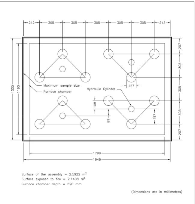
Exact internal dimensions of the furnace along with the location of the loading apparatus are shown in Figures 5 & 6. In the horizontal position, a separate add-on frame is used to apply appropriate loading on the test specimen. Four hydraulic jacks, each fitted with three pads, apply the load in a uniform manner. An integral loading frame fitted with six hydraulic pistons applies the load in the vertical position as shown in Figure 6. The vertical loading frame is installed at the bottom of the intermediate-scale furnace contrary to the NRC full-scale wall-testing furnace. For this reason, the weight of the specimen must be taken in consideration for net load calculations on the test specimen.
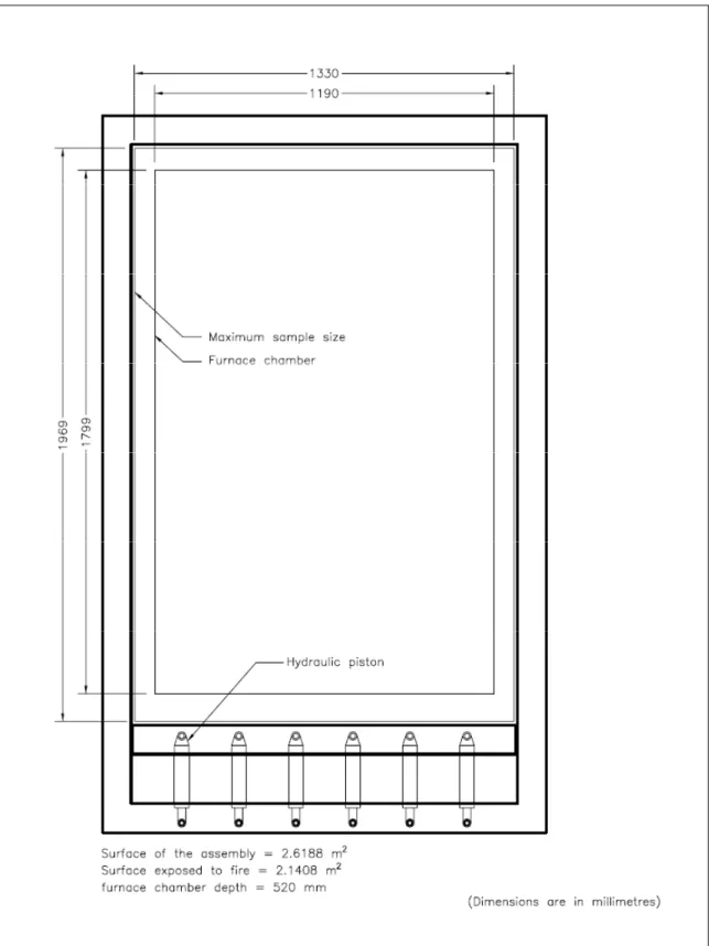
Figure 6 Intermediate-scale Furnace Internal Dimensions in the Horizontal Position (Floor Furnace)
Figure 7 Intermediate-scale Furnace Internal Dimensions in the Vertical Position (Wall Furnace)
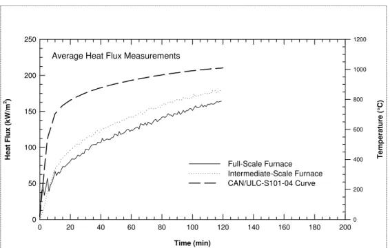
6.0 FULL-SCALE AND INTERMEDIATE-SCALE FURNACE COMPARISON
The intermediate-scale furnace, used in its floor configuration, is approximately 1/6 the size of the full-scale floor furnace. To ensure that the intermediate-scale furnace is able to provide results comparable to those of a full-scale furnace, a study (13) was carried out that involved exposing the specimen to heat, using propane-fired horizontal and vertical furnaces of different sizes. The results showed the severity of the fire in the intermediate-scale furnace to be slightly higher than in the full-scale furnace. IRC researchers will continue to study the results obtained from full-scale and intermediate-scale furnaces to determine more precisely the correlation between them.
Time (min) 0 20 40 60 80 100 120 140 160 180 200 He a t Fl ux (kW/ m 2) 0 50 100 150 200 250 T e mpe ratur e ( °C) 0 200 400 600 800 1000 1200 Full-Scale Furnace Intermediate-Scale Furnace CAN/ULC-S101-04 Curve
Average Heat Flux Measurements
Figure 8 Comparison of Heat Exposure (Full-Scale vs Intermediate-Scale)
7.0 INSTRUMENTATION & FURNACE SPECIFICATIONS SUMMARY
• Data Acquisition System / Video Equipment:
o Total Number of Readily Available Channels: 80
o Thermocouple Channels: 70 (K Type, Chromel-Alumel)
o Deflection Measurement Channels: 3
o General Purpose Analog Channels: 4
o Specific Channels: 3 (load, 2 air pressure)
o Current Measurement Channels: 8 (not readily available)
o Program Sampling Period: Variable but typically 1 min or 5 s.
o Number of Video Cameras/Recorders: 3
o Recording media: DVD (with timestamp & test info.)
• Furnace Specifications:
o Number of Burners: 4
o Burner Maximum Capacity: 73KW (292kW total)
o Viewing Ports: 2
o Furnace Orientation: Horizontal & Vertical
o Maximum Specimen Load in the Horizontal Position: 218.2 kN
o Maximum Specimen Load in the Vertical Position: 117.7 kN
o Maximum Specimen Size (Horizontal): 1949mm x 1330mm
o Maximum Specimen Size (Vertical): 1969mm x 1330mm
o Furnace Chamber Depth: 520mm
8.0 INTERMEDIATE-SCALE FURNACE CABABALITIES
The intermediate-scale furnace can be used to test fire resistance for loaded and unloaded concrete walls, beams and slabs as well as lightweight wall and floor assemblies. Also, it can be used for testing objects that can fit inside the furnace for heat transmission to the inside of the object. Tests can be conducted in accordance to the time-temperature curve specified in CAN/ULC –S101, ASTM E119, and ISO standards as well as a non-standard time-temperature curves.
9.0 ACKNOWLEDGEMENTS
The authors wish to acknowledge the contribution of J. W. MacLaurin.
10.0 REFERENCES
1. CAN/ULC-S101-04, Standard Methods of Fire Endurance Tests of Building Construction and Materials, Underwriters' Laboratories of Canada, Scarborough, Ontario, 2004.
2. ASTM E119-88, Standard Test Method for Fire Tests of Building Construction and Materials, American Society for Testing and Materials, West Conshohocken, PA, USA, 1988.
3. ISO 834-1999, Fire-Resistance Tests – Elements of Building Construction – Part 1: General Requirements, International Organization for Standard, Case postal 56, CH – 1211, Geneve, Switzerland.
4. Eclipse Velocity Burners ThermJet Series Version 1.00 Installation Guide No. 205, Eclipse Combustion, 1997.
5. DCP301 Digital Program Controller User’s Manual, Honeywell, 1999.
6. M7261, M7272, M7274, M7281, M7282, M7284, M7285, M7286, M7294, Modutrol IV Motors, Honeywell, 1993.
7. Veri-Flame Monitoring Systems, Bulletin 818C, Eclipse Combustion, 1999.
8. Agilent 34970A Data Acquisition / Switch Unit User’s Guide, Agilent Technologies, 1999.
9. Agilent 34970A Data Acquisition / Switch Unit Service Guide, Agilent Technologies, 1999.
10. VEE Pro User’s Guide, Agilent Technologies, 2000.
11. VEE Pro Advanced Programming Techniques, Agilent Technologies, 2000.
12.
DP41-E High Performance Process Indicator Operator’s Manual, Omega, 1999. 13. Sultan, M.A., "Furnace tests : the National Research Council of Canada isinvestigating a way to test the fire resistance of wall and floor assemblies that is more economical than doing full-scale tests," Canadian Consulting Engineer, 44, (3), May, pp. 28, 32, May 01, 2003 (NRCC-46410)