Development and Implementation of a Combined Discrete and
Finite Element Multibody Dynamics Simulation Environment
by
Petros Komodromos
Diploma of Civil Engineering, University of Patras, Greece Master of Science in Civil and Environmental Engineering, MIT
Submitted to the Department of Civil and Environmental Engineering in partial fulfillment of the requirements for
the degree of
Doctor of Philosophy in Information Technology at the
MASSACHUSETTS INSTITUTE OF TECHNOLOGY MASSACHUSETTSINSTITUTE
OF TECHNOLOGY
September 2001
SEP
@ Petros Komodromos, 2001. All Rights Reserved.
The author hereby grants to MIT permission to reproduce and dis- LIBRARIES tribute publicly paper and electronic copies of this thesis document
in whole or in part.
ENG
A u th o r ... ... Department of Civil and Enyromental Engineering June 27, 2001
Certified by ... ... ... Johna=R. Williams Associate Professor, Department of il and Environmental Engineering
Thesis Supervisor
A ccepted by ...
Oral Buyukozturk Chairman, Departmental Committee on Graduate Studies Department of Civil and Environmental Engineering
Development and Implementation of a Combined Discrete and Finite Element Multibody Dynamics Simulation Environment
by
Petros Komodromos
Submitted to the Department of Civil and Environmental Engineering on June 27, 2001, in partial fulfillment of the requirements for the degree of
Doctor of Philosophy in Information Technology
Abstract
Some engineering applications and physical phenomena involve multiple bodies that undergo large displacements involving collisions between the bodies. Considering the dif-ficulties and cost associated when conducting physical experiments of such systems, there is a demand for numerical simulation capabilities. The discrete element methods (DEM) are numerical techniques that have been specifically developed to facilitate simulations of distinct bodies that interact with each other through contact forces. In DEM the simulated bodies are typically assumed to be infinitely rigid. However, there are multibody systems for which it is useful to take into account the deformability of the simulated bodies.
The objective of this research is to incorporate deformability in DEM, enabling the evaluation of the stress and strain distributions within simulated bodies during simulation. In order to achieve this goal, an Updated Lagrangian (UL) Finite Element (FE) formula-tion and an explicit time integraformula-tion scheme have been employed together with some sim-plifiying assumptions to linearize this highly nonlinear contact problem and obtain solutions with realistic computational cost.
An object-oriented extendable computational tool has been built specifically to allow us to simulate multiple distinct bodies that interact through contact forces allowing selected bodies to be deformable. Database technology has also been utilized in order to efficiently handle the huge amounts of computed results.
Thesis Supervisor: John R. Williams
Acknowledgments
First, I would like to thank my thesis advisor, Prof. John Williams, and my professors and doctoral committee members, Prof. Jerome Connor and Kevin Amaratunga, for all the valuable advise, guidance and help they have provided to me throughout my graduate studies at MIT. I could not have made it without their help and support.
I am also grateful to many professors during my graduate studies, both here at MIT and at the University of California at Berkeley, for the valuable knowledge and education they have offered me. I am particularly grateful to Prof. George Kocur for his support and the insightful discussions we had, and to Prof. Bathe for his valuable advise. I am also extremely grateful to my professors during my undergraduate studies at the University of Patras in Greece, in particular to Prof. Dimi-tris Beskos, Michalis Fardis and Stavros Anagnostopoulos.
Next, I would like to thank my many-many good friends that I have been fortunate to have here at MIT and Boston, who have made my life much better and happier. Although I would like to thank everyone of them individually, this is impossible in these few lines. Therefore, I have to limit it to few who had the most impact on my academic and personal life.
First, I would like to thank my very close friends Debjit Das, Mathew Kurian, and Ben Cook, whose help has been the most critical during my studies and life at MIT. I am extremely thankful to them for everything they have done for me, especially for providing the most invaluable advise not only regarding my Ph.D. work, but also my personal life. I am also very grateful to all my friends here at the Civil Engineering Department, in particular to Bharath, Sugata, Sudarshan, JP, George (Constantinides), Noelle, Emilio, Eric, Kiran, Siva, Sameer, Achilleas, Sofoklis, Dimitris, Chang, Nadine, Yijun, Emma, Moon-Seo, Sang Jyun, Fuxin, Julio, Jingsong and Constantinos.
There are no words to sufficiently thank my buddy, Joannie McCusker, for everything she has done for me. She has always been a main source of strength and support for most students of the Information Technology group. Also, I am very grateful to Anthee, Elaine, Stephanie, Jessie, Cyn-thia and Maria for their support, help and care, making my student life much smoother.
I would also like to express my gratitude and thanks to many good friends outside the CEE Department, especially my dear Greek and Serbian friends, who have made my life in Boston much more colorful. Many-many thanks to my very dear friend Eleni, who has been a source of strength, reminding me always, in the most noble way, our beloved country, Cyprus. Many-many thanks to my dear friends Peggy, Rada, Thalia, Sophia, and Constantinos (Boussios) for the great company and friendship they have offered me. I have been so fortunate to have so many good Greek friends through the Hellenic Students Association of MIT that it is practically impossible to thank them all individually. Thanks to all of them for everything!
Last but not least, I would like to thank my family and friends in Cyprus and Greece for believ-ing in and supportbeliev-ing me. It is indeed a blessbeliev-ing to have them all emotionally so close to me. Their unconditional love, emotional support and encouragement have always been my driving force in pursuing my goals and fulfilling my dreams. I would like to specifically thank my grandparents, George and Chrisanthia; my sister Marina, who has been next to me during all hard times I went through; the sweetest and most lovable girl I have ever met, Marina Cocconi, and her parents; my best friends Georges, Zenon, Andreas, George, Marios, Stefanos, Katia, Michalis and Nondas; my sister Christina; and all my cousins, uncles and aunts, especially Elena, Alexis, Georgio, Maria, Michalis, Dora, Lefteris, Lia, Yianna, Jason, Irene, Metaxas, and Herodotos. Finally, it is difficult to find words to express my love and gratitude to my parents, Androulla and Yiannis, whose love, encouragement, and understanding have always been a constant source of motivation and strength for me. Without their endless support and courage this achievement would not have been possible. A lifetime is too short to pay off all the sacrifices they have done to enable my studies and goals.
A$1cpogEvo, pe oXi1 gou nv ayan, Tous yovELs po. Dedicated with all my love to my parents
Table of Contents
1 Introduction...15
1.1 M otivation... 15
1.2 Discrete Elem ent M ethods... 18
1.2.1 Description ... 18
1.2.2 Advantages and lim itations ... 20
1.2.3 Classes of DEM ... 21
1.3 Applications ... 22
1.3.1 Granular m aterials ... 22
1.3.2 M asonry structures ... 24
1.3.3 Rock m asses ... 27
1.3.4 Fragm entation and blasting ... 27
1.3.5 Realistic m ultibody anim ations ... 28
1.3.6 M ultibody dynamic and m echanical system s ... 28
1.4 Literature Review... 28
1.5 Thesis Objectives... 30
1.6 Thesis Outline ... 31
2 Object Representation and M odeling ... 35
2.1 Introduction... 35
2.2 Review of previous work... 36
2.2.1 Superquadratic geometric representation ... 37
2.2.2 Discrete function representation (DFR) ... 38
2.3 Selected Geom etric Representation ... 41
2.3.1 Polyhedral representations: cuboids and rectangular shapes ... 41
3 Contact Detection and Forces...43
3.1 Introduction... 43
3.2 Contact Detection Schem es ... 44
3.3 Selected Contact Detection Procedure... 46
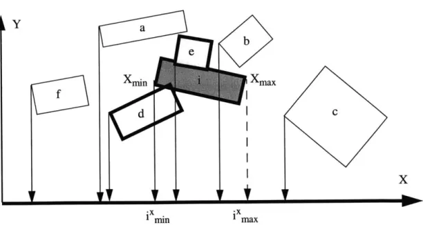
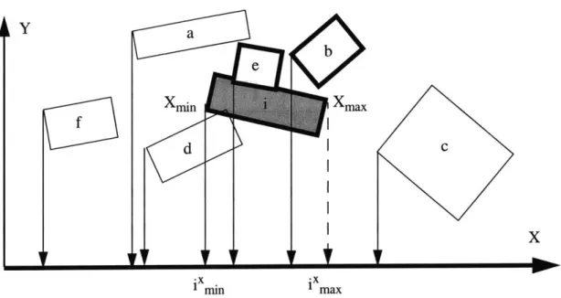
3.4 Spatial Reasoning Phase ... 48
3.4.1 Spatial sorting: based on bounding boxes ... 48
3.4.2 Spatial searching: identification of potential pairs of bodies ... 49
3.4.3 Exam ple of 2D spatial reasoning ... 50
3.5 Pairwise Contact Detection Checks ... 53
3.5.1 Spatial overlapping tests ... 53
3.5.3 Contact plane ... 58
3.6 Contact Data Structure... 60
4 Physics of the Problem ... 63
4.1 Introduction... 63
4.2 Contact Effects ... 64
4.2.1 Assum ptions and sim plifications ... 64
4.2.2 Selected contact approach ... 65
4.2.3 Com putation of contact force ... 66
4.2.4 Contact stiffnesses, Coulomb friction and energy dissipation ... 68
4.2.5 Application of contact forces on infinitely rigid bodies ... 69
4.3 Equations of M otion ... 70
5 Consideration of the Deformability of Simulated Bodies...73
5.1 Introduction... 73
5.1.1 Traditional finite element formulations for contact problems ... 74
5.1.2 Sim plified finite elem ent model and form ulation ... 75
5.2 Finite Elem ent Form ulation ... 76
5.2.1 Continuum m echanics equations ... 77
5.2.2 Finite elem ent m atrices ... 81
5.2.3 Application of contact forces ... 86
5.2.4 Dynamic analysis and numerical integration of equations of motion ....87
5.2.5 Isoparam etric FE form ulation ... 89
5.2.6 Num erical integration ... 92
5.2.7 Im plem entation of the FE form ulation ... 93
5.3 Potential Future Extensions ... 97
5.3.1 Large strains form ulation ... 97
5.3.2 Fracturing and fragm entation capabilities ... 98
6 M esh Generation... 99
6.1 Introduction... 99
6.2 Structured Grids...100
6.3 Unstructured Grids...101
6.4 Selected M esh Generator ... 103
6.4.1 Introduction ... 103
6.4.2 M esh description ... 104
7 Softw are D esign and Im plem entation...113
7.1 Softw are D esign O verview ... 113
7.2 Com putational Considerations: Java vs C++...114
7.3 Com puter G raphics Considerations ... 120
7.3.1 Selection of a graphics library ... 120
7.4 G raphical U ser Interface Considerations ... 123
7.4.1 Selection of G U I fram ew ork ... 123
7.5 U tilization of D atabase Technology ... 124
7.5.1 M otivation for using database technology ... 124
7.5.2 Potential future extension ... 126
7.6 Structure of the Softw are Application ... 129
7.6.1 Preprocessor m odule ... 129
7.6.2 Com putationally intensive part ... 130
7.6.3 Postprocessor m odule ... 131
7.7 Softw are design...132
7.8 Softw are Im plem entation...133
7.8.1 Java language ... 133 7.8.2 Java 3D API ... 137 7.8.3 Sw ing ... 149 7.8.4 Java2D ... 154 8 A pplications...155 8.1 Introduction...155
8.2 V erification Exam ples ... 155
8.2.1 Exchange of m om entum ... 155
8.2.2 W ave propagation ... 158
8.2.3 Rigid body colliding on a constrained deformable body ... 161
8.2.4 Energy dissipation during contact ... 162
9 C oncluding R em arks ... 165
9.1 Sum m ary ... 165
9.2 Contributions and Conclusions ... 167
9.3 Future W ork ... 168
Appendix A DAFES Graphical User Interface (GUI)...171
A .1 D AFES M enu ... 173
A .1.1 File subm enu ... 173
A . 1.2 Param eters subm enu ... 173
A .1.4 Tools subm enu ... 174
A .1.5 View subm enu ... 175
A .l.6 Rendering subm enu ... 176
A .1.7 Printout subm enu ... 177
A.2 D AFES controller: control buttons ... 177
Appendix B Large Strain Considerations...181
B .1 Introduction...181
B.2 Total Lagrangian Form ulation ... 181
Appendix C Source Code ... 191
C.1 M ergesort algorithm to sort an N-Size array ... 191
C.1.1 C++ version ... 191
C.1.2 Java version ... 192
Figure 2.1 Figure 2.2 Figure 2.3 Figure 2.4 Figure 2.5 Figure 3.1 Figure 3.2 Figure 3.3 Figure 3.4 Figure 3.5 Figure 3.6 Figure 3.7 Figure 3.8 Figure 3.9 Figure 4.1 Figure 4.2 Figure 4.3 Figure 5.1 Figure 5.2 Figure 5.3 Figure 6.1 Figure 6.2 Figure 6.3 Figure 6.4 Figure 6.5 Figure 6.6 Figure 7.1 Figure 7.2 Figure 7.3 Figure 7.4
List of Figures
Body-related class hierarchy. ... 37
Exam ple of 2D D FR ... 39
Sampling of values for 2D DFR...40
Physical-Storage mapping of sampled values...40
Boundaries of a cuboidal and a rectangle...42
2D space subdivision schemes...46
Contact detection phases. ... 47
Bodies in the 2D X-Y plane. ... 50
Spatial Sorting in the X-direction... 52
Spatial overlapping test between two rectangles...54
Sampling points used for contact resolution. ... 55
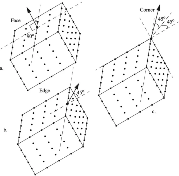
Normal vectors at sampling points of a rectangular body...56
Normal vectors at sampling points of a cuboidal body...57
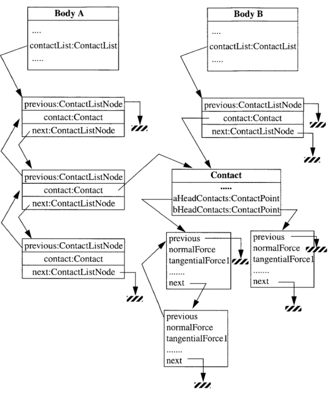
Contact storage data structure. ... 61
Pipeline of analyzing a physical problem through idealizations...63
Computation of contact forces. ... 67
Computation of the contact forces resultants. ... 69
Configurations of a moving body at times 0 and t. ... 78
Configuration of body at times 0 and t... 82
Isoparam etric 2D FE. ... 94
Voronoi diagrams and Delaunay triangulation in a plane...102
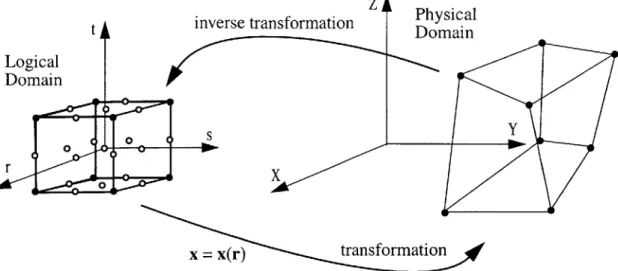
Logical and physical domain mappings...105
M eshing of a 2D elem ent. ... 105
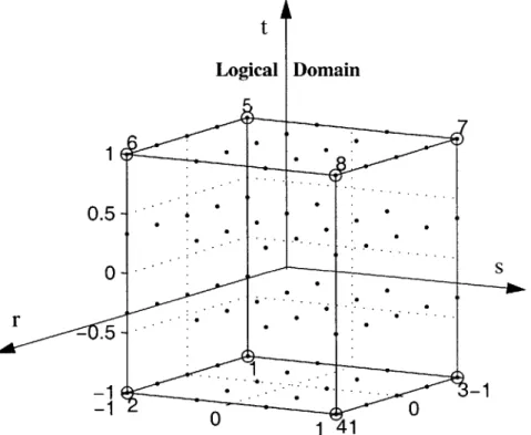
Logical and physical dom ain...108
Meshed reference cube in logical domain...109
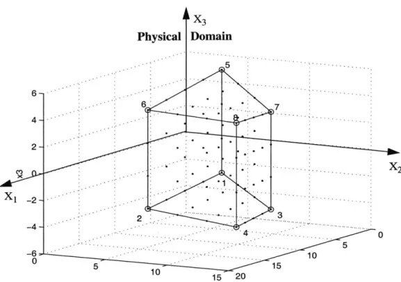
Meshed cuboidal element in the physical domain...111
Time required to sort an N-size array ... 115
Performance Comparison of C++ and Java using a mergesort ... 116
Time required to perform multiplication of two NxN size arrays...117
Figure Figure Figure Figure Figure Figure Figure Figure Figure Figure Figure Figure Figure Figure Figure Figure Figure Figure Figure Figure 7.5 7.6 7.7 7.8 7.9 7.10 7.11 7.12 7.13 8.1 8.2 8.3: 8.4: 8.5: 8.6: 8.7 : 8.8 : 8.9 : 8.10 8.11
: Particle Collision Simulator (PACSIM)...121
: Architecture of DAFES ... 126
: Potential future DAFES architecture combined with AMOS-II. ... 128
: Sim ulation pipeline. ... 129
: Scenegraph example...139
: Class hierarchy of major subclasses of the SceneGraphObject class...140
: Class hierarchy of the IndexedGeometryArray class...142
: VirtualUniverse, Locale and View classes...145
: Default coordinate system of Java3D...148
: Centrical collision of a body with an initial velocity ... 156
: Displacements of the centroid of the bodies. ... 156
: Kinetic energy of the two infinitely rigid bodies . ... 157
: Energy of the two deformable bodies during simulation. ... 158
: Rod-shape deformable body colliding to a fixed infinitely rigid body...159
: Stresses TXX at a center node of the deformable body. ... 159
Stresses TXX at an edge node of the deformable body...160
Rigid body moving towards a constrained deformable body...161
Snapshots from a rigid body collision ... 162
: Deformable bodies falling under gravity ... 163
: Displacements of falling bodies under gravity on restrained bodies...164
: D A F E S . ... 17 1 : Options of File submenu. ... 173
: Options of Parameters submenu...174
: O ptions subm enu...174
: T ools subm enu...175
: V iew subm enu...176
: Rendering submenu...176
: Printout subm enu...177
: Controller of DAFES...179
: Configurations at time 0, t and t+At...182
: Physical interpretation of the deformation gradient. ... 187
Figure A.1 Figure A.2 Figure A.3 Figure A.4 Figure A.5 Figure A.6 Figure A.7 Figure A.8 Figure A.9 Figure B.1 Figure B.2
List of Tables
Table 3.1: Ordering of bodies in X-direction based on their minimum bounds...51 Table 3.2 : Selection of bodies that may be in contact with body i...52 Table 5.1 : Sampling points and weights for Gauss Quadrature ... 93
Chapter 1
Introduction
1.1 Motivation
In many physical phenomena and engineering applications there are systems with large numbers of distinct bodies that undergo large displacements and rotations involving con-tacts between the bodies of the system. Examples range from particulate granular materi-als, such as soil, to multibody systems, such as masonry structures. Such discontinuous systems are characterized by the contacts that occur between the moving distinct bodies of the system and the freedom of the individual bodies to move in space under the action of the forces that are exerted on them.
A major category of discontinuous systems is granular materials, which can be found
in many applications. In engineering practice, the macroscopic behavior of granular, or particulate in general, materials is defined assuming that the material is continuous. Bulk material properties and empirical rules based on observations and experiments at the mac-roscopic level are employed. Continuous idealizations of the behavior of granular materi-als are used, assuming that local perturbations at the particle level have negligible effects at the scale of length of interest. Essentially, the continuity assumption allows character-ization of the macroscopic behavior of the system using bulk material properties by aver-aging the interactions that occur at the particle level. This assumption may be justified in some cases by considering that the microstructure length scale is much smaller than the
dimensions of the problem under investigation and assuming that local perturbations at the particle level have negligible effects at the scale of interest.
However, macroscopic behavior depends not only on bulk material properties but also upon the properties and geometric information of the constituent bodies, such as the size and shape of the particles, their distribution, packing density, interparticle friction, and particle-to-particle interaction laws. In essence, the macroscopic behavior of particulate materials depends on the properties of individual particles and their interactions. For gran-ular materials, such as sand and gravel, the deformation and load transfer are mainly due to rearrangements of the particles and interparticle contacts, respectively.
Therefore, it is useful to study particulate systems at the particle level, and not as a continuum, to better understand the macroscopic behavior and how it is affected by parti-cle-level characteristics. Besides the need for more accurate modeling of particulate sys-tems, the understanding of the relationship between microscopic parameters and macroscopic behavior is essential for the development of more rational constitutive mod-els for granular materials. Physical experiments at the particle level are almost impossible to be performed, since any instrument installations change the physical problem character-istics. Therefore, computational tools that allow numerical simulations of such discontinu-ous systems are required.
Discrete element methods (DEM) research is motivated and driven by the need to pro-vide numerical means to simulate and study particulate and multibody systems (Cundall
[5], [6] and [7], and Williams et al [23]). The DEM provide alternative numerical means to
simulate multiple interacting bodies undergoing large motions in order to observe and record detailed interactions occurring at the particulate level. Although DEM have been introduced as a tool to study granular soils and rock masses, they can also be used to model and study many other physical problems that involve large numbers of moving and
colliding distinct bodies. Numerical simulations of multibody systems are useful, not only for understanding the behavior of particulate systems, but also for making engineering decisions that are necessary for the design and analysis of systems that process and trans-port particulate systems.
In general, the DEM assume that the simulated bodies are infinitely rigid, which is a reasonable assumption for many particulate systems. For example, the deformation of granular materials is mainly due to the rearrangement of the particles (Rege [26]) and not the particle deformations, and the stress distribution within a particle is not of interest.
However, there are multibody systems, such as masonry structures, for which it is desirable to be able to obtain the stress and strain distributions within the bodies as they collide with each other. The research presented in this thesis has been motivated and driven by the need to provide numerical means to simulate and study multibody systems that may be deformable, allowing the evaluation of the stresses and strains within the sim-ulated bodies. In order to enable the consideration of deformability of simsim-ulated bodies and the evaluation of their stresses and strains distributions, an Updated Lagrangian (UL) Finite Element (FE) formulation and an explicit time integration scheme have been employed together with some simplifying assumptions to linearize this highly nonlinear contact problem and obtain solutions with realistic computational cost.
An extendable, object-oriented and portable computational tool has been built to enable numerical simulations of multiple distinct bodies that interact through contact forces while allowing selected bodies to be deformable. Since huge quantities of results are computed, database technology has also been utilized in order to efficiently store, search and manipulate them.
1.2 Discrete Element Methods
1.2.1 DescriptionThe discrete element methods (DEM) are numerical techniques specifically developed to simulate multiple distinct bodies that interact through contact forces (Cundall [5], [6] and [7], and Williams et al [23]). The main capability of DEM is that they allow the simulation
of assemblages of multiple unrestrained distinct bodies that interact through contacts. Each discrete element, i.e. body, has distinct boundaries, which physically separate it from each other element in the analysis, and interacts with other bodies only with contact forces whenever the bodies are identified to collide with each other.
A major characteristic of the DEM is that they allow fast and efficient automatic
rec-ognitions of new contacts as well as complete detachments of bodies, which were previ-ously in touch, during simulations. Since the greatest difficulty in simulations of large number of interacting bodies is the contact detection and the determination of the contact forces, the DEM give priorities to these aspects and make some simplifying assumptions so as to make the problem tractable.
The numbers of distinct bodies that are required to be used in such simulations range from several bodies, in the case of multibody systems, to several thousands, or even mil-lions, in the case of granular systems. The use of a large numbers of bodies is often required when simulating a particulate system so as to have a representative sample of the physical problem. In order to be able to model systems with large numbers of interacting, through contact forces, discrete bodies, emphasis is put on the most computationally intensive part of the problem is the contact detection.
A typical assumption of DEM is that the constituent bodies, or particles, are infinitely
rigid, which substantially reduces the computational cost. This assumption is made con-sidering either that the deformations of each body are negligible under the expected
load-ings, or, in the case of particulate systems, that the overall strains of particulate materials are mainly due to the relative sliding and packing between particles and much less due to deformation of individual particles. In the case of particulate systems, such as granular soil, the individual particles are very stiff relative to the mineral skeleton of granular mate-rials, which is usually deformable.
In addition, multibody systems are typically modeled in DEM using a very simple geometric representation of each distinct body, such as spheres, to facilitate fast contact detection algorithms. With these, and several other assumptions, close to real-time interac-tive simulations can be performed with the current computing capabilities.
Other assumptions include simplified representations of contact effects, which are used, often in the form of idealized springs, to decouple the problem. When two bodies come in contact, forces must be applied to the bodies to push them apart. Two different approaches are used: the hard contact approach and soft contact approach. The decision of which contact representation to use depends on the nature of the problem and the quanti-ties of interest.
When the hard contact approach is used, no interpenetration is allowed while displace-ment compatibility in the normal directions as well as equilibrium and constitutive law must be satisfied. No contact springs coefficients need to be defined, which is a major problem in the soft contact approach. The collisions are usually assumed to be very brief and they are typically modeled as instantaneous exchanges of momentum. However, this approach is computationally very costly since iterations may be required, and it is difficult to ensure displacement compatibility at all contacts while satisfying equilibrium, constitu-tive laws, and conserving momentum and energy. In addition, considering the bodies to be infinitely rigid while prohibiting contact overlapping is somehow unrealistic because in reality the colliding bodies have some local deformations at the contact locations.
According to the soft contact approach, which is used in this thesis, a finite normal stiffness is assumed to exist and, in consideration of the actual deformability at the vicinity of the contact, some overlapping of the bodies in contact is allowed. In physical problems overlapping and interpenetrations of bodies do not take place, but surface deformations instead allow these relative movements. The magnitude of the contact forces is assumed to start from zero when the bodies first come in contact and increases as the bodies interpen-etrate each other up to a maximum value and then starts decreasing and eventually becomes equal to zero when the bodies detach from each other.
1.2.2 Advantages and limitations
Although standard numerical methods are available to model discontinuities to some extent they are not specifically developed to solve, with reasonable computational cost, assemblages of many interacting discrete bodies. In DEM emphasis is placed on the effi-cient object representation and fast contact detection. Appropriate simplified assumptions are made to allow simulation of many discrete bodies with sufficient geometric details. However, for numerical simulations of systems with very large numbers of bodies, the main limitation is still the computational cost for contact detection. That cost increases with the number of discrete bodies and the complexity of the geometry of each individual body.
Most discrete element (DE) algorithms make some simplifying assumptions, typically, assuming infinitely rigid bodies with simple geometric shapes, such as spheres, and simple representations of contact effects, to reduce the high computational cost. Although in some cases these assumptions are reasonable and justified by the need to make the prob-lem tractable, there are certain probprob-lems for which it would be useful if more accurate mathematical models are used. This thesis addresses the cases in which the deformability of the individual bodies needs to be taken into account. The consideration of the
deform-ability of simulated bodies is achieved by employing a large-displacement finite element methods (FEM) formulation, which is efficiently combined with the DEM.
1.2.3 Classes of DEM
The discrete element methods (DEM) have been introduced in the late '60s early '70s as tools to simulate granular materials (Cundall [5], [6] and [7], and Williams et al [38]).
There has been a great interest in these numerical techniques in the past decade, especially during the last few years. Substantial research has been done in the area of contact detec-tion algorithms leading to significant reducdetec-tions of the required computadetec-tional time. There are many different classes of DE formulations and computer programs. The main classes of DE formulations are the following:
* Distinct (or discrete) Element Programs: Soft contacts are used, while the bodies
may be rigid or deformable, (Cundall [5], Williams et al [38]). This is the main DE formu-lation and the one that is used in this thesis. Direct integration methods, such as explicit numerical schemes, may be used to numerically solve the equations of motion.
. Modal Methods: Modal decomposition is employed in these methods to solve the equations of motion (Williams and Pentland [39]). The rigid body motion and strain-dis-placement equations for each distinct body may be decoupled. Then, the deformability of each discrete body can be expressed in terms of its eigenvectors that correspond to the non-zero frequency eigenmodes. Depending on the desired accuracy the number of included modal contributions may be selected properly. The zero frequency eigenmodes result in rigid body motion, i.e. the motion is decoupled into a rigid body motion and a rel-ative motion that results in internal body deformations. These methods can be used to con-sider the deformability of discrete bodies in loosely packed systems.
- Discontinuous Deformation Analysis: In this approach contacts are considered rigid while bodies may be assumed infinitely rigid or considered deformable (Shi [29] and
[30]). Iterations are required to ensure that no interpenetrations between distinct bodies
able to simulate large numbers of interacting bodies. However, large time steps may result in missing contacts or overlaps that may occur over the time step. In addition, in the case of external load with high frequencies, the representation of the externally applied load may be very inaccurate.
- Momentum Exchange Methods: These are the simplest methods in which both contacts and bodies are assumed rigid. No penetration is allowed and the collisions are assumed instantaneous. Motion is determined by momentum exchanged between two con-tacting bodies during an instantaneous collision.
Numerical methods to model materials at finer level than that considered by DEM have been developed and used, such as the cellular automata and the lattice gas methods. These methods can simulate materials at a microscopic, or even molecular, level.
1.3 Applications
Although DEM have been initially developed to simulate fractured rock masses and gran-ular soils, they can be used for many other applications that involve discontinuous, or, in general, multibody systems that undergo large displacements and rotations as well as col-lisions among the moving discrete bodies. Numerical simulations of multibody systems with graphical visualization capabilities can provide valuable information and insight of the behavior of such systems avoiding actual physical experiments, or costly manufactur-ing and testmanufactur-ing of prototypes. The followmanufactur-ing are some of the many potential applications for which DEM can be used for numerical simulations.
1.3.1 Granular materials
A granular material is a collection of a large number of distinct particles that are not
con-nected with each other. Such particulate materials are very common in many different areas of nature and engineering. Since there is no generally accepted theory for granular materials, DEM can be used to study them at the particle level subject to external
excita-tions, such as oscillaexcita-tions, providing very useful information about their behavior.
A major category of granular materials is that of granular soils, in geomechanics,
whose macroscopic behavior is heavily influenced by interactions between the constituent particles, and particle-level properties, such as size, shape and distribution of individual particles. DEM simulations allow the identification of the effects of microscopic proper-ties to the overall macroscopic behavior, such as the effect of the particle shape on the macroscopic behavior. Numerical simulations can also reveal phenomena that occur at the particle level, but are difficult to be captured in actual physical experiments without dis-turbing the samples (e.g. Rege [26]). More rational macroscopic constitutive behavior of granular soils may be developed, based on the findings of numerical simulations at the particle level, than those based on continuity assumptions. In addition, DEM may be used to simulate and observe physical phenomena at the particle level, such as the failure pro-cess in a slope stability analysis.
DEM can also be used to study the behavior of other granular materials. The manufac-turing and transportation of granular materials, such as powders in manufacmanufac-turing indus-tries, cereal grains in food indusindus-tries, and tablets in pharmaceutical industries may be simulated with DEM. Phenomena such as the segregation, which often occurs during vibrations of granular materials can also be studied with DEM. Segregation is observed when mixtures containing different size particles are subjected to vibrations, which usu-ally result in rising of large particles and falling of the small particles at the bottom. In addition, flow of granular materials in industrial applications, e.g. through oscillating hop-pers, which mainly depends on contacts between the constituent particles, can also be modeled using DEM. Wave propagation through granular materials, which sometimes are used as shock absorbers to isolate sensitive equipment, can also be studied using DEM.
Finally, a defense-related application is the study of a projectile penetration of a mis-sile into granular materials, e.g. sands. A similar application is the simulation of a footing of a structure under dynamic loading. In particular, discrete elements can be employed to model the soil below the footing enabling the simulation of the penetration of the footing in the soil due to dynamic loadings, such as earthquake excitations.
1.3.2 Masonry structures
Analysis tools for masonry structures are very important for the maintenance and restora-tion of historic structures. The dynamic analysis of masonry structures is a rather chal-lenging problem due to the discontinuities of these structures. Masonry structures, such as those built from stones and bricks, are typically analyzed with very crude empirical rules using estimated static loads to take into account seismic effects. Considering the increas-ing interest in studyincreas-ing old masonry structures, DEM analysis can capture the discrete behavior of these structures providing a better understanding of their response and their potential failure mechanisms under earthquake excitations. Old masonry buildings were, typically, been built without any earthquake resistant design. In addition, the excessive weight of masonry structures due to over dimensioned walls and high material densities, results in high seismic loads. Finally, non-proper design, e.g. eccentricities and deteriora-tion of the quality of the materials (stone, bricks and mortars) make these structures very vulnerable to earthquake excitations. Therefore, a better understanding of the dynamic behavior of these structures is very important. These structures exhibit a highly nonlinear behavior when excited to earthquake excitations which is very difficult or even impossible to capture with classical methods. Typically, limit analysis is used to perform stability analysis using equivalent static loads.
Although some FEM (using smeared cracks or special "gap elements"), finite differ-ence methods (FDM), and boundary element methods (BEM) models have been used for
simulations of these discontinuous structures, certain difficulties arise mainly due to the continuity approach of these methods. These methods are ineffective in modeling many interacting bodies, especially for dynamic analysis, since they are based on continuity assumptions. The "smeared cracking technique", and the "gap elements" or the "no-ten-sion contact elements" that have been used in FEM have limited capabilities and the anal-ysis often becomes unstable. For quasi-static problems the "limit analanal-ysis" has been used for stability studies, but it is limited only for static problems and does not provide any information for the collapse process.
However, equivalent static forces cannot adequately represent the earthquake excita-tions and the resulting dynamic response of the masonry structures. DEM provide alterna-tive numerical means to simulate masonry structures in order to obtain their dynamic response and their failure mechanisms under extreme events, without the need of building costly laboratory tests or using very simplified static analysis. The dynamic response of these structures involves rocking and impact as well as sliding of the brick or stone blocks which cannot be modeled by any other method.
The structure can be modeled as a system of many distinct bodies put together in the same way that the structure had been physically constructed, and allowed to interact through contact stresses with their adjacent bodies. Each distinct body can be modeled as a single rigid, or deformable, discrete element, while element interactions are modeled using idealized contact and cohesive springs. DEM can be used to more realistically simu-late blocks, such as bricks or stones, separated by joints, as well as joint-mortar using cohesion bonds. The opening and closure of joints, crack formations, sliding and rocking can be modeled with the DEM, which is almost impossible with other standard numerical methods. Phenomena such as cracking and separation of parts of the structure into various
smaller parts that vibrate in different ways due to different frequencies, which result in fur-ther destruction, can be studied using the DEM.
It is not only masonry buildings that can be analyzed using DEM, but also masonry bridges as well as any kind of masonry structure. DEM can allow the dynamic simulation of these structures under earthquake excitations allowing more accurate and realistic anal-ysis and, in case of failure, the observation and recording of the initiation and progress of the collapse pattern.
The dynamic response of such structures can be easily obtained for many different earthquake excitations that can be applied to the foundations of the structure, providing valuable information for the assessment of the seismic vulnerability of such structures. For problems that are dominated by in-plane behavior, 2D DEM can be used. To consider the flexibility of the individual blocks plane stress or plane strain FEM can be combined with
2D DEM, which is exactly the problem that is addressed in this thesis.
DEM can also used to perform quasi-static numerical simulations of masonry struc-tures subjected to slowly applied lateral loads to get an estimation of the static lateral forces that cause structural collapse. Although limit analysis may be used for static load-ings to determine the collapse static load, using DEM more realistic and detail representa-tion of a discontinuous structure can be made. The DEM results may be compared with "limit analysis" results to verify the DEM model and the selected mechanical properties.
In addition to the large displacements and efficient contact effect representations of DEM, the methods also allow a realistic modeling of the mortar joints using "cohesion" bonds combined with certain strength and failure criteria. The degradation of mortars can also be modeled by changing their mechanical properties according to certain criteria dur-ing the simulation. Usdur-ing flexible bodies, it is also possible to consider the stones' or bricks' deformability or even strength allowing fracturing to occur. Finally, it may be
pos-sible to take into account existing reinforcement by incorporating some special structural elements in the simulation combined with failure criteria.
1.3.3 Rock masses
DEM can also be used for simulations of rock formations, such as those studied in rock
mechanics. Dynamic stability analysis to consider seismic excitations and other dynamic loadings can be performed using DEM instead of the currently used equivalent static anal-ysis. Then, the dynamic response, including the slip and separation of rocks at points of contact, as well as the failure pattern can be simulated. If the DEM tool has deformable bodies then the deformations and stress distribution of the individual rock bodies can also be computed.
1.3.4 Fragmentation and blasting
One of the first applications of DEM was to study the impact effects of sea-ice flow on off-shore structures (Williams et al [40]) and in general the fracture process of ice around the structure. DE formulations have been developed (e.g. Munjiza [17]) that allow the discrete bodies to undergo progressive fracturing resulting in automatic generation of more in number and smaller in size bodies to model the fragmentation process. Fracture criteria need to be defined so as to determine the fracturing of distinct bodies into more than one new distinct bodies. Fragmentation phenomena, which are studied in fracture mechanics, can be simulated using DEM.
Another area where DEM may be useful to perform numerical simulations is that of explosions, blasting in mines (Taylor and Preece [29]), and controlled demolitions of structures. It is very interesting to be able to model explosive fragmentation of an assem-blage of bodies, which fracture and break into multiple bodies, and do particle tracking studies. For this kind of problems the distinct bodies have not only large displacements
and rotations, but also large strains and consequently non-linear material behavior, due to the very high load pressures, making the problem much more difficult.
1.3.5 Realistic multibody animations
DEM may also be used to create more realistic multibody animations used in computer graphics, virtual reality, video games and cartoons by incorporating mechanics into the animations. In recent years there is an increased interest in developing realistic physical animations in computer aided design and virtual reality environments, e.g. for educational and training simulations. More realistic multibody animations and more meaningful numerical simulations can be performed by combining engineering-oriented numerical techniques with computer graphics algorithms supplemented with contact detection algo-rithms.
1.3.6 Multibody dynamic and mechanical systems
There are practical applications that involve both mechanical systems, and large numbers of particles interacting together. Simulations of such systems may be possible by incorpo-rating in DEM simple mechanical system formulations, which allows optimization of the design product prior to the actual manufacturing.
1.4 Literature Review
A detailed literature review of DEM and related procedures is provided by O'Connor [21].
Here, the research done and the contributions made specifically in the Intelligent Engi-neering Systems Laboratory (IESL) at MIT are briefly described.
Rege [26] developed a computational materials laboratory, named Modeling Interact-ing EngineerInteract-ing Systems (MIMES), which is a user-friendly two-dimensional discrete ele-ment program. MIMES can be used as a simulation environele-ment to perform numerical experiments of planar problems with bodies of arbitrary shapes. Using MIMES, Rege was
able to study granular material behavior in 2D from a particle perspective and to capture detail information of individual particles during simulations. In particular, Rege performed a series of biaxial compression tests in order to study the effect of different microscopic parameters, such as particle size, shape, and distribution, as well as confining stress and loading rates. These tests indicated the presence of coherent, vortex-like, structures, named circulation cells, which may influence the global failure of the specimen. These coherent structures, which essentially are groups of particles that instantaneously translate
and rotate as rigid bodies, grow forming eventually failure bands.
O'Connor [21] developed an efficient object representation and contact detection algo-rithms. In particular, O'Connor developed a scheme, named Discrete Function Represen-tation (DFR), to model complex 3D geometries and facilitate fast contact detection algorithms. He also used parallel computing to distribute the computational work over a number of processors.
Klosek [14] extended the 2D DE program developed by Rege incorporating fluid flow using Finite Elements Methods (FEM) to approximately model the fluid and calculate fluid pressures. Klosek also developed numerical techniques to calculate the fluid forces on arbitrary shape bodies.
Chiou [3] used the Discrete Function Representation (DFR), which was originally developed by O'Connor [21], to simulate large numbers of 3D infinitely rigid bodies. He implemented a hashtable-based spatial reasoning algorithm for similar size bodies to fur-ther reduce the computational time for contact detection. He also enhanced the original sequential contact detection algorithm to enable parallel processing.
Cook [4] has studied the fluid flow through granular material using an extended ver-sion of MIMES, in which he incorporated the lattice-Boltzmann numerical method in order to be able to direct simulate solid-fluid systems at the grain level. In particular, Cook
has formulated and implemented an accurate, efficient, and robust modeling capability for the direct simulation of solid-fluid systems. Cook used a highly efficient numerical scheme based on the discrete-element (DEM) and the lattice-Boltzmann (LB) methods to solve the coupled equations of motion governing both the fluid phase and the individual particles comprising the solid phase. He used the coupled method, which he had incorpo-rated into MIMES, for simulation and analysis of two-dimensional solid-fluid physics demonstrating its accuracy and robustness over a wide range of dynamical regimes. He was able to reproduce in simulations various fundamental phenomena, including drafting-kissing-tumbling interactions between settling particles, and the saltating transport regime of bed erosion.
1.5 Thesis Objectives
In DEM the constituent bodies of a system are, typically, assumed infinitely rigid in order to reduce the computational cost. However, there are multibody systems for which it would be useful to be able to consider the deformability of selected individual bodies in the numerical simulations. The incorporation of flexibility of individual bodies in the sim-ulation would allow the calcsim-ulation of the stress distributions as well as the resulting strains in the simulated bodies, which would be very useful in some applications. This is the main issue that is addressed by this thesis.
The deformability of the individual bodies is taken into account using a large-displace-ments finite element (FE) formulation coupled with the discrete element procedures. The additional computational cost, which is a critical implication of the incorporation of FE into a DE simulation tool, has been carefully addressed taking into account the available computational resources and making proper simplifying assumptions.
A spatial reasoning approach is used in this thesis to reduce the cost of the contact
detection and allow simulation of systems with large numbers of bodies of different sizes moving within a non-limited simulation volume. An object representation scheme, which directly extendable in 3D, is used to represent the simulated bodies.
The goal of this thesis and research is to develop and implement simplified efficient numerical procedures that can simulate multibody systems taking into account the deformability and the distribution of stresses within the individual bodies. The following issues are addressed in the thesis:
- development of an efficient contact detection algorithm - simulation of contact interaction
- efficient modeling of deformable discrete elements
- utilization of object-oriented programming and database technology
In addition, although the actual implementation of the software due to lack of comput-ing resources is limited to the 2D case, the implementation has been done in an extendable program that can be easily enhanced and used for 3D simulations. In particular, all the architecture of the program, such as computer graphics, vectors, methods, have been developed as 3D.
1.6 Thesis Outline
In this chapter, an introduction to the problem that this thesis addresses is presented. First, the motivation for the development and use of discrete element methods is discussed, fol-lowed by a general description and some applications of these methods. Then, the research work that has been previously conducted by our group here at MIT, is presented. Finally, the thesis objectives and expected contribution are briefly stated.
Chapter 2 discusses the object representation and modeling, which is selected to enable an efficient contact detection procedure. The contact detection algorithms and pro-cedures are presented in Chapter 3. After a brief introduction to contact detection methods and related issues the selected procedure is discussed in detail. In particular, the spatial reasoning and the contact resolution phases are presented. The chapter concludes with a discussion about the contact forces that are applied during collisions and contacts between the simulated bodies.
Chapter 4 presents the underlying physics of the numerically simulated problem. In particular, the physical laws that govern the motion of the simulated bodies and the simpli-fied assumptions in order to efficiently take into account the contact effects are described.
The major part of this research work is the incorporation of the deformability of the individual bodies, which is discussed in Chapter 5. In particular, a large-displacements/ small strains finite element formulation is coupled with a discrete element procedure. Some simplifications and assumptions were necessary in order to reduce the complexity of the problem and be able to realistically execute numerical simulations with multiple bod-ies considering the currently available computational resources.
Since the computational requirements are usually very high, it is desirable to use a simple and efficient mesh generation procedure that facilitates fast FE meshing and analy-sis. This issue is discussed in Chapter 6, which starts with an introduction to grid genera-tion techniques, followed by a descripgenera-tion of the main categories of grids. Then, the selected mesh generator, in particular an algebraic mesh generator that generates structure grids, is described in detail
The software design and implementation is presented in Chapter 7, beginning with an overview of the design. The benefits of object-oriented programming are stressed, fol-lowed by a description of the structure and the components of the simulation tool that has
been developed. Then, a description of the technology that has been used to develop the software is briefly described. A paragraph of this chapter discusses how database technol-ogy can be utilized to efficiently manage the input data and output results.
Chapter 8 provides applications of the software that has been developed, which is named DAFES (Discrete And Finite Element Simulator). Simple verification examples that demonstrate simple phenomena, such as the exchange of momentum, the conservation and dissipation of energy, and wave propagation are presented.
Finally, Chapter 9 provides a summary of the work that has been done, followed by conclusions that have been made. Finally, this chapter concludes with some remarks and suggestions regarding future work.
In addition, three appendices are provided at the end of the thesis with supplementary material. In particular, Appendix A presents the graphical user interface of DAFES, Appendix B discusses how large strains can be taken into account using FEM in a poten-tial extension of this work towards that direction, and Appendix C presents the source code that has been used to compare the performance of C++ and Java.
Chapter 2
Object Representation and Modeling
2.1 Introduction
The selection of a suitable geometric object representation is very important for the simu-lations under consideration, since it should facilitate both the computationally expensive contact detection and the Finite Element (FE) meshing and analysis. The contact detection process, which is used to identify the bodies that are in contact during simulation, is typi-cally the major computational bottleneck in simulations of multiple infinitely rigid bodies.
Many object representation schemes have been developed and extensively used in computational geometry and computer graphics, such as constructive solid geometry
(GSC), boundary representations (B-Rep.), and methods using explicit, implicit and
para-metric surface representations. GSC objects are described using intersections, unions or subtractions of simpler objects. Implicit, explicit and parametric surfaces are defined by mathematical functions. B-Rep explicitly lists boundary features of objects, such as faces, loops, edges and vertices.
However, many of these representation methods are inefficient either for contact detec-tion, or for FE meshing purposes. Therefore, the object representation should be selected based on its suitability for efficient contact detection checks between the simulated bodies and FE meshing. A compromise may be necessary as the most suitable representation for contact detection may be very inefficient for FE meshing and analysis.
In particular, the geometric object representation scheme should facilitate the contact resolution phase of the contact detection. As it is explained in detail in the following chap-ter the contact detection that has been selected consists of two phases, the spatial reason-ing and the contact resolution. Since for the spatial reasonreason-ing module boundreason-ing boxes are used, the selection of the object representation should be based on its suitability to facili-tate the contact resolution module. The latter checks whether a pair of bodies that are selected by the spatial reasoning are indeed in contact and in that case determines the con-tact geometry. The concon-tact geometry is used together with the history of the motion of the bodies to compute the contact forces that need to be applied to the bodies in contact.
2.2
Review of previous work
The superquadratic geometric representation and the Discrete Function Representation (DFR), which was originally developed by O'Connor [21], are presented here as an exam-ple of an effective representation that has been used in DEM. Although it has not been used in the coupled DE/FE simulation environment that has been developed, it can be used in the future to extent the program in considering bodies with a general shape.
The currently developed software implements the classes and methods that refer to the simple geometric shapes that have been selected, in particular rigid and deformable rect-angular bodies. However, the class hierarchy as shown in Figure 2.1, allows easy exten-sions of the program to consider any other shape as long as the associated methods that are required for the simulation modules, such as the contact resolution, are implemented.
In this research effort, the DFR has not been utilized as the bodies that had been imple-mented were of simple geometrical shape. However, the developed program is extendable and the DFR is considered to be one of the most promising representation schemes to
rep-resent bodies of more general shape. Therefore, it is prep-resented here for completeness, although more detail information is presented in O'Connor [21].
Figure 2.1: Body-related class hierarchy.
2.2.1 Superquadratic geometric representation
The superquadratic representation is an implicit function that can be used to describe the geometry of the simulated bodies. An implicit function, such as the superquadratic, facili-tates fast inside/outside tests, since it is easy to determine whether a point lies inside or outside the boundary of the object that is expressed by the function. In addition, the major-ity of solid geometric objects can be sufficiently well represented by a superquadratic function.
A superquadratic function is an implicit analytical expression that geometrically defines
the boundary of a two dimensional (2D) body. Its general, 2D equation has the following form:
F(x, y) = .X + 2- 1.0 = 0.0
where the coefficients CX and C specify the lengths of the principal axes of the geo-metric object, and, the exponents px and p control the shape of the surface.
For example, the family of superquadratics with P= P = 2 corresponds to ellip-soids, while the special case of equal coefficients, e.g. C = Cs,, corresponds to a circle.
Similarly, the three dimensional (3D) superquadratic function can be used to describe the boundary of a 3D geometric object, and its general equation is:
xpx Py pz
F(x, y, z) = - + 2-L + Z - 1.0 = 0.0 (2.2)
CX C, Cz
where the coefficients C,, C,, and Cz specify the principal axes of the geometric object, and, the exponents pX, pY , and pz control the shape of the surface.
A point can easily be tested whether it lies inside, outside or on the boundary surface
of a geometric object. The following cases should be considered:
- if F(x, y, z) > 0.0, the point (x, y, z) is located outside the object's surface
- if F(x, y, z) = 0.0, the point (x, y, z) is located on the surface of the object - if F(x, y, z) < 0.0, the point (x, y, z) is located inside the object's surface
2.2.2 Discrete function representation (DFR)
The Discrete Function Representation (DFR), which was originally developed by O'nor [21], can be used to represent arbitrary geometric objects. It facilitates a very fast con-tact detection procedure that requires only O(M) computations to perform concon-tact resolution between two bodies that may be in contact.
In particular, a grid of a certain resolution is imposed slicing the object's volume to cubical voxels. Values are, then, assigned at each intersection of the grid using the equa-tion that describes the object's geometry, e.g. the superquadratic equaequa-tion.
The following two dimensional example demonstrates the use of DFR to represent the geometry of a 2D object. In order to use DFR to represent a 2D object, such as that in Fig-ure 2.2.a, a 2D grid is used to slice the body into a set of squares, as it is shown in FigFig-ure
2.2.b. At the intersection points of the grid values of the function that describes the
object's geometry are computed and stored to represent the boundary of the object.
Fx0
HxJY >9 F x,J ) 0
a. Object to be represented with DFR b. Use of Figure 2.2: Example of 2D DFR.
a 2D grid for DFR
The boundary of the object can be approximated using the values at the intersections of the grid to compute with interpolation the intersection points of the object's boundary with the squares of the grid.
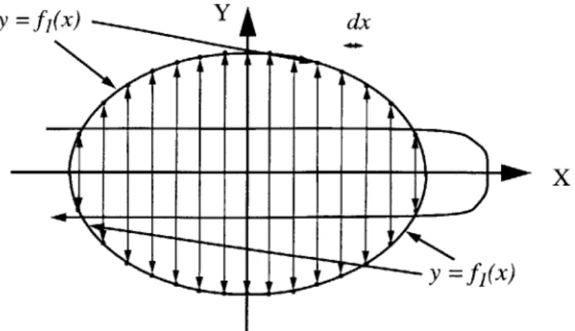
The boundary of the object is treated as a pair of single-value functions, y =
f
I(x)and y = f 2(x). Values of these functions are sampled at a certain uniform resolution dx,
as shown in Figure 2.3, using the local coordinate system, and stored.
701
1000'
...
...
X
y = fj(x)
Figure 2.3: Sampling of values for 2D DFR.
The values from the uniformly sampled boundary points are then stored in an array using a direct mapping between the x-coordinate and the storage space, which enables fast retrieval of values, Figure 2.4.
Figure 2.4: Physical-Storage mapping of sampled values.
Having an implicit function, f(x, y, z) = 0, a point (xi, yi, zi) corresponds to a value
f(xi, yi, zi) of the function. The values of the function can be considered as samples of a
scalar potential field that represents the volume of the shape that is defined by the implicit function. This approach is similar to the technique that is used in the Magnetic Resonance Imaging (MRI), where the scalar values measure the material density.
The 3D DFR data structure provides an efficient way of enclosing a simulated body with a set of cells, which is called discrete bounding hull (DBH), that intersect the 3D body. The sampling grid is used as the local coordinate system for each body with unit the cell size.
2.3 Selected Geometric Representation
In general, most DEM use spherical objects as they provide simplicity and efficiency dur-ing contact detection. The typical use of spherical objects is also justified by the common encounter of such shapes in simulations of very large numbers of discrete bodies. How-ever, in simulations where there is interest for the stress and strain distributions within individual simulated bodies and the number of bodies is relatively not very large, the most typical shape is polyhedral. In particular, rectangular and box shape bodies are very com-mon in 2D and 3D problems, respectively. Rectangular bodies are the ones selected to be implemented using a essentially a B-Rep representation scheme.
2.3.1 Polyhedral representations: cuboids and rectangular shapes
Polyhedral representations are composed of polygons that have certain relationships and constraints to one another forming solid objects. For example a rectangular shape object in
2D and a cuboidal-shape object in 3D can be represented by their bounding edges and
faces, respectively. The objects are described, according to the B-rep., in terms of their bounding entities, such as faces, edges and vertices.
The bounding relations of the cube are based on the six faces, each of which is bounded by four edges, and each of the latter is bounded by two vertices. Similarly, a rect-angular object is bounded by the four edges, each of which is bounded by the correspond-ing vertices.