HAL Id: hal-02200539
https://hal-cstb.archives-ouvertes.fr/hal-02200539
Submitted on 31 Jul 2019HAL is a multi-disciplinary open access
archive for the deposit and dissemination of sci-entific research documents, whether they are pub-lished or not. The documents may come from teaching and research institutions in France or abroad, or from public or private research centers.
L’archive ouverte pluridisciplinaire HAL, est destinée au dépôt et à la diffusion de documents scientifiques de niveau recherche, publiés ou non, émanant des établissements d’enseignement et de recherche français ou étrangers, des laboratoires publics ou privés.
A versatile and extensible solution to the integration of
BIM and energy simulation
D. Mazza, E. El Asmi, S. Robert, Khaldoun Zreik, Bruno Hilaire
To cite this version:
D. Mazza, E. El Asmi, S. Robert, Khaldoun Zreik, Bruno Hilaire. A versatile and extensible solution to the integration of BIM and energy simulation. eWork and eBusiness in Architecture, Engineering and Construction - Proceedings of the 11th European Conference on Product and Process Modelling, ECPPM 2016, Sep 2016, Limassol, Cyprus. �hal-02200539�
Paper published in: Proceedings of the 11th European Conference on Product and Process Modelling (ECPPM2016), Limassol, Cyprus, 7-9 September 2016, eWork and eBusiness in Architecture, Engineering and Construction – Christodoulou & Scherer (Eds) Taylor & Francis Group, p. 165-173 [ISBN 978-1-138-03280-4]
A versatile and extensible solution to the integration of BIM and energy simulation
D. Mazza, E. El Asmi & S. Robert
CEA, LIST, Gif-sur-Yvette, France
K. Zreik
CiTu Paragraphe, Université Paris 8, Paris, France
B. Hilaire
CSTB Sophia Antipolis, France
ABSTRACT: Energy simulation represents now a critical step of the building design process, but the integration between BIM authoring tools and simulation tools is still a source of issues and problems. Most simulation engines still require the definition of a specific input model, thus making impossible to directly use the BIM model information to configure and run simulations. The lack of agreements on standards for simulation input files makes software integration between BIM and simulation tools insufficient. With this aim, this paper presents a software framework for BIM-Simulation integration aiming at both effectiveness and extensibility. An intermediary conversion step for the generation of simulation specific yet tool-agnostic building design model (here called Building Simulation Model) allows to tackle the problem through a two-step generation scheme (BIM-to-BSM and BSM-to-simulation tool) leveraging the principles of the Model-Driven Engineering methodology. Targeted engines have been EnergyPlus and COMETH (the French regulatory thermal engine) in the scope of an on-going European project (FP7 HOLISTEEC).
Keywords: BIM, Energy simulation, integration, model conversion, MDD, MDE
1 INTRODUCTION
Energy simulations play nowadays an important phase of the building design process. Energy consumption is one of the main aspects tackled in current times, and it has really become a sensible issue for clients towards the sustainability of the living practices of our and future society. For these reasons, the current building design process cannot avoid to take this aspect and all the related issues into consideration in the proper and detailed way. Evaluation of energy consumption is usually performed starting from a CAD-authored building model and given as input to energy simulation tools that compute the energy consumption of building different areas (thermic zones) over a specified period of time (e.g. a year).
Integration between authoring tools and simulations engines is still source of issues and problems, due to the lack of widely-adopted standards for the specification of building information or (wherever standards are
present) to the lack of direct integration through adopted data format between authoring tools and simulation engines. In the following BIM models and related context will be referenced by the BIM acronym, while the simulation engines specific formats and context will be referenced by the SIM acronym.
This article presents a framework for the BIMSIM integration, which exploits the concepts of the model-driven methodology for the conversion of a BIM model into a SIM one. A model-based approach is straightforward, given the need of converting a BIM model into a SIM. Indeed simulation engines do not accept BIM models as direct inputs, and an engine-specific model should be created starting from the BIM one. BM-SIM conversion can be represented as a model-to-model conversion, thus the concepts developed by the model-driven branch of software engineering can help providing best practices and well-developed procedures for conversion.
2 BIM AND ENERGY SIMULATIONS
BIM-SIM integration is complex because of the different points of view adopted by BIM and SIM by simulation engines to perform computations. In particular:
− simulation engines generally do not directly accept BIM models as input. Thus the need of model conversion to SIM model
− additional data not originally provided with BIM models are needed for SIM models (e.g., physical properties of materials). BIM models usually represent geometric information while simulation engines need different information to perform calculations. Thus the need of integrating the inputted SIM model
− simulation engines usually adopt proprietary formats for their models in input. Thus a once for-all conversion is not possible due to the need to be separately addressed each simulation engine.
These issues likely clarify the needs for an environment that could manage the input of BIM building projects to simulation engines. Such framework should be able to abstract the specific features and the technicalities of each single simulation engine and should be able to provide a procedure that, by focusing on the main aspects of the conversion of a model from a BIM format to a simulation engine-specific format, could allow to a generalization of the conversion procedure in order to possibly target different simulation engines.
This the purpose of the work here presented and of the framework described in the following.
3 A FRAMEWORK FOR THE BIM-SIM CONVERSION
The main concern in interfacing BIM and SIM worlds is to guarantee that the same building project and its characteristics are considered and conserved in both domains. Equivalence of the considered models is thus the driving
1EnergyPlus is one of the most known and used
simulation engines in building design and AEC domain.
criterion and rationale. A simulation engine is used indeed to verify specific energy-efficiency or consumption constraints, thus considering the same building under design is of utmost importance.
Model conversion is at the core of the BIM-SIM integration here proposed. This is anyway a nontrivial task:
− conversion cannot be as easy as a 1-to-1 correspondence between BIM—and SIM-model elements. Indeed for one BIM object more than one SIM objects need typically to be specified
− not all BIM elements have a corresponding SIM element. Different realms tackle different concepts
− specific parameters or object properties cannot be directly mapped (e.g., value treatment during conversion is required) or are not defined in the target model
− origin and target model could propose a way to model real building objects from different points of view, thus leading to a lack of information and data to be used during the conversion, which should be integrated somehow.
In order to specifically tackle the above issues, this work proposes an approach to BIM-SIM model conversion based on an extensible architecture, where those general issues common to all BIM-to-SIM conversions can be managed once-for-all, without further customization or intervention, and when those conversion logics specific for a targeted simulation engine can be fine-tuned by the user and adapt to the specific needs of each case.
This work stemmed from an original approach devoted to the specification of conversion procedure addressing EnergyPlus1 as target
simulation engine, and later extended to another proprietary simulation engine called
COMETH (COre for Modelling Energy and THermal comfort), developed and sold by CSTB
(the French Centre for Building Science and Technology). The design of the solution for the latter engine highlights the existence of common needs and logics to generalize and apply to the conversion process, which led to a
Further details can be found on the official web site: http://apps1.eere.energy.gov/buildings/energyplus/
refinement of the original solution for more structured software architecture. A
model-driven design approach has been adopted,
which is explained in the following. 3.1 The model-driven methodology
The model-driven methodology is an approach of designing solutions to problems where models play a key role. The idea behind such approach is to obtain a solution to a problem through the transformation of an initial model into another one. In the software engineering domain, models are used to abstract objects and their features for the need of a specific model to be able to describe a general solution regardless its final delivery (i.e., technology or platform on which this solution has to run or execute). This Platform-Independent Model
(PIM) contains all the relevant information and
concepts to completely describe the solution from a general point of view.
The idea underlying model transformation is then the possibility of converting the initial PIM into a more specific model that represents a solution for the problem on a specific platform, leading to what is called Platform-Specific
Model (PSM). Model-to-model transformation
therefore involves mainly a transformation of the concepts (model objects) information (model data, objects features) from the initial, abstract model to a low level, technology-specific model, thus “rearranging” the original information and objects in order to build up a solution-specific model. Obviously, the advantage of such an approach is that different PSMs, one for each specific platform, can stem from the same PIM, as shown in Figure 1.
Figure 1. The model transformation process.
The model-driven approach has therefore been applied in our case: by considering the definition of a general simulation model, that we called Building Simulation Model (BSM), we
represent a way to model the building under study adopting an energy- simulation point of view. This way it is possible to model all the concepts involved in energy simulation at a higher and abstract level: this model is our PIM and it is a simulation engine-independent way of describing a building. Through a model transformation procedure we can then obtain a PSM for the simulation engine of interest (Energy- Plus, COMETH, others at need). The PIM model contains the necessary information in order to transform the model to the specific PSM. Information exchange between the PIM and PSM is thus an important specification step. The use of a standardized framework as Information Delivery Manual
(IDM) describes the process of data exchange
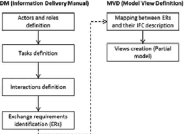
for the BIM domain. It is developed by the BuildingSmartR Association, and it allows specifying the data to exchange among the involved parties through the use of a standardized format. The IDM can thus be generally meant as formalism to model the process of information exchange for the BIM domain. Involved concepts are related to a specific target domain (e.g., energy simulation in the particular case of this work). IDM will then be translated by IFC experts and leads to a second document named MVD (Model View Definition), defining a subset of the IFC schema focusing on the information to exchange.
Figure 2 sketches the whole process.
Figure 2. The transformation process of IDM to MVD.
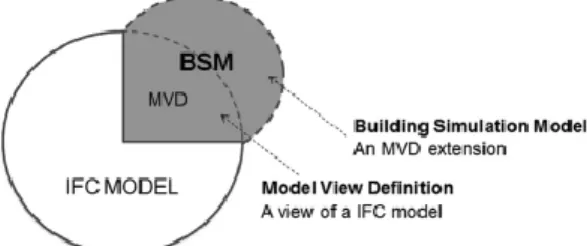
For energy simulation, we are defining a SIM-MVD describing the IFC elements we need to exchange to move from a BIM to a SIM model. In parallel, missing IFC entities will be specified and developed by IFC experts to fully describe
the SIM model; the combination of the SIM-MVD with the missing IFC entities, will corresponds to what could be called a Building Simulation Model (BSM) (cfr. Figure 3).
Figure 3. BSM as an extension of IFC concepts and data.
To sum up, in energy simulation domain and regarding the model-driven methodology, a specific PIM model can be defined and considered as a BSM. And by using IDM-MVD methodology, we are able to define its content. 3.2 Solution design and implementation In order to adopt the explained model-driven approach, there was the need of a model able to catch all the aspects covered by simulation models, thus a model that could play the role of common denominator for all the engine-specific simulation models.
The introduced Building Simulation Model (BSM) plays the role of the PIM in the context of the model-driven approach explained before. In our case, the platform-independency has to be meant as simulation engine-independency: in order to target multiple simulation engines, we need an abstract model that allows us to catch those concepts related to the simulations, and not linked to a specific engine. BSM plays this PIM role, while in our case the role of PSMs are played by the engine-specific models required by the targeted simulation engines.
BSM model contains all the objects for the geometric definition of a building (storey, ceiling, floor), its detailed elements (door, window, wall), and detailed composition of elements (material). Each object has a set of associated properties that represent the peculiarities of each instance (i.e., a specific door, wall or window) of a single object type. Properties describe the different aspects of an object, that can be again related to its geometry (e.g., width, height), its properties
related to its object type (e.g., the color) or related to its nature (e.g., the composition material, usually a reference to a material meant as another object).
The BSM model has been defined incrementally: an initial version of BSM has been defined with the purpose to abstract from the specific input format accepted by EnergyPlus, the first targeted simulation engine; at a later stage of the work, the BSM has been adapted and extended in order to cover and abstract the additional modeling peculiarities needed by the input format of COMETH, the second targeted simulation engine. During this adaptation process for the latter simulation engines, some aspects were already covered by the first BSM version defined for targeting EnergyPlus, thus highlighting indeed the possibility of identifying a minimum set of simulation-specific concepts common to all the simulation engines.
Extension to the first initial BSM with additional elements of features has been necessary to cover simulation aspects that were not needed for the definition of the EnergyPlus simulation model; anyway, only those non-COMETH specific details have been added, in order keep the BSM as an engine-independent simulation model, as detailed in the following.
3.2.1 energyplus vs. COMETH models
EnergyPlus and COMETH models differ in terms of the concepts used for modeling building and its thermal characteristics.
While the former adopts mainly a geometrybased building modeling, with the further specification of the thermal properties of the involved objects, the latter adopts a thermal engineering point of view, thus defining for defining the building through its separation in thermal zone, and the specification of the characteristics of these elements in terms of heat exchange.
EnergyPlus model stresses more on the geometry of the building, and then decorates the elements with the specification of those physical properties necessary for energy simulation computations; the COMETH model consists instead of project composed of a set of
zones (i.e. thermal zones) defined according to
their use and considered in groups, each representing a homogeneous thermal unit. This unit then contains a set of walls, windows and thermal bridges that model the heat exchange between adjacent zones.
The differences in building modeling capabilities between the two simulation engines have raised issues in the specification of the common BSM model, that had to be adapted to manage properly those information specific of given model. It is worth mention how the EnergyPlus model better link with the IFC building model, given their common geometric approach in building specification. For the sake of generalization, adaptation of BSM model due to the peculiarities of COMETH model has thus been necessarily introduced. 3.3 Model-to-model conversion
The initial building model for the overall process is a BIM model. As such model, BuildingSmartR IFC (Industry Foundation Classes) has been considered as the building design format of reference; it is therefore the input format of the procedure presented in this work. This choice has been mainly driven by the role of standard that IFC would like to play in the BIM world and, despite the still rather limited number of commercial products and authoring tools currently supporting IFC as storage format, its use and adoption among practitioners have been increasing in recent years.
For this work, IFC4 (the latest one) is considered as the reference version, and all conversion procedures have been designed starting from this version.
The design procedure consists therefore in two model-to-model transformation:
− the first step is the conversion from IFC to BSM. Indeed IFC contains all the necessary information to model a building from the geometric point of view, but it is not a format developed to support energy simulations. This first conversion is therefore necessary to adapt the IFC model to a simulation-oriented model, like BSM wants to be
− as further step, the conversion of BSM to a simulation engine-specific format is then performed.
Each model transformation is performed by dedicated converter in the architecture of the framework that it is explained in Section 3.4.
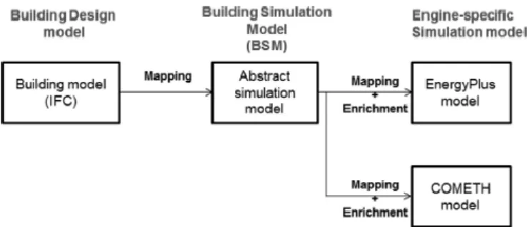
Figure 4 sketches the overall conversion process. With respect to the first conversion, from IFC to BSM, it is worth remarking here that IFC projects mainly describe buildings as a set of interconnected objects; it is mainly a geometric, structural description of buildings. Of course, this information are useful for the definition of simulation models, which have the need as well to describe buildings from a structural point of view; anyway, simulation engines need also other information to perform their task, e.g., material properties or other physical attributes, which can allow them to build an inner energy model to perform computations.
Figure 4. The overall conversion process.
These additional data cannot be retrieved from IFC projects and must be separately supplied during the conversion process in order to build up a complete simulation model.
Materials and related data provide a good example for information missing in IFC projects to be integrated to the generated BSM model. Indeed, in a BSM model materials need to have physical and energy-related properties specified, all information that a IFC project does not originally contain; usually IFC files contains material names or other properties for general reference, but no more specific information about materials. In order to create a complete BSM, material information have been provided and integrated to the building project through the aid of an external database that, containing the additional information related to material and relevant for energy simulation purposes (e.g. physical properties
such as material conductivity, roughness; etc.), has allowed us to add such information in the IFC project file, specifying these data as additional properties to be associated with specific materials. Thanks to the addition of these extended data, a complete BSM could be defined, thus easing the further conversion step towards the engine-specific simulation model.
With respect to the second conversion, from BSM to engine-specific format, it is worth notice here that additional data could be needed here as well, but in this case these data are specific settings expected by the targeted simulation engine. These data can be fixed parameters setting, that could cover most of the simulation engine uses, or other parameters that can be fine-tuned by the user and therefore set before the execution of the converter. could cover most of the simulation engine uses, or other parameters that can be fine-tuned by the user and therefore set before the execution of the converter.
3.4 Architecture of the conversion framework In order to perform the BIM-SIM conversion, software architecture for the converter has been put in place. In particular, during the design of the software architecture the attention has been put into the specification of
converter and engine-specific elements.
Specifically:
− converter elements are those software elements that perform the conversion procedure and that do not change with respect to the target simulation engine − on the other side, engine-specific elements
are those elements that are responsible of the conversion and of the construction of destination model specific of a target simulation engine. This way, these components are supposed to implement those conversion logics that define the specific way in which the model-to-model transformation has to occur according to the targeted simulation engine, and these are therefore the components that are likely to be redefined (or the logics implemented by them) modified in order to perform the conversion for the destination simulation engine.
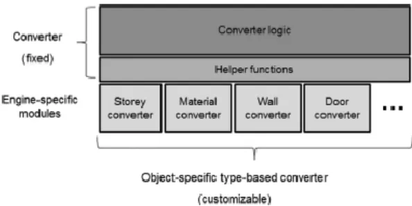
Figure 5 explains the schema of the converter architecture, highlighting fixed and variable parts.
Figure 5. The conversion framework architecture.
The converter parts have the purpose of analyzing and scanning the input file in order to identify the composing elements, and to perform pre- or postprocessing operations when necessary. These elements coordinate the overall conversion procedure.
The engine-specific parts are devoted to the conversion of specific objects: according the type of the recognized object, a specific set of rules is applied for the conversion. This
type-based conversion allows the user to define the
conversion logics by re-defining and
customizing the rules implemented by those
modules devoted to the conversion of a specific object type. This way, a general conversion procedure can be put in place, by leveraging on two main axes: a) the type of the object to convert b) the targeted simulation engine.
3.5 Modularization and customization of the
conversion software procedure
All the conversion software architecture is implemented according in an object-oriented fashion through specific C++ objects devoted to the performance of specific conversion tasks.
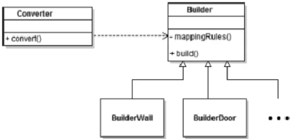
Figure 6 shows the objects that compose the framework; specific methods exposed by these objects are expected to be redefined and overridden according to the targeted simulation engine for which the model conversion procedure has to be implemented: − Converter is the object that performs the
actual conversion procedure, through the execution of its convert() method
− Builder is the abstract object devoted to the conversion of specific model object; builder objects for different objects types are expected to the derived from this abstract object.
Figure 6. The UML diagram of the foundation objects of the conversion framework.
Customization of the conversion procedure is thus implemented through the overriding of the methods of these specific classes; in particular, the overriding of method convert() of Converter object allows to define the order and the prioritization of the conversion for each specific object type, while the overriding of the method mappingRules() of the Builder object allows to specify the conversion rules according to the object type.
3.6 Evaluation of the approach
The approach for the evaluation of a model transformation has mainly to verify that the output model contains those concepts of the input model that can be specified in the former, representing according the format allowed by the latter.
In order to verify this, the typical technique adopted in the model-driven is formal checking (Buettner et al. 2012). This approach consists thus in the definition of a set of constraints (or conditions) supposed to be conserved during the model transformation and that the output model has to possess and present. In particular, it can be easily understood how part of the information of the output model or the way in which data are structured and related each other can depend a) on the information and data provided by the input model b) can be additional parameters/elements not present in the input model or derived from the information of the input model; in this case, the
values of this additional parameters can be constant values or data derived (directly, or indirectly thus through further elaboration/computation) from input model data.
Formal checking techniques have thus been applied by testing the model transformation approach on the test case described in the following for both the simulation engines (EnergyPlus and COMETH) considered in this work. The test has consisted in executing the conversion procedure starting from the IFC4 project file as input and converting it for the use by a simulation engine. Given the differences in the conversion procedure, and the different concepts (point of view) of the two simulation engines, the approaches to define the goodness of the conversion have to be different between the two engines, because some measures or aspects taken into consideration by the EnergyPlus model are not described in the COMETH one, and vice versa. Preliminary step for evaluation is the generation by the conversion procedure that guarantees the executability of the generated model by the targeted simulation engine. Although this step does not say anything particular about the goodness of the quality of the model conversion, it represents anyway an obvious but necessary condition for the evaluation of the approach.
3.7 Test case
The solution has been tested on a real project of a family house, designed and then constructed in Southern France. For this project, the original IFC4 files created by the engineering company that managed the project were available.
The house of the test case has 1 floor, 4 main rooms and 1 other service space, and the project defines also the position, dimension and materials of doors and windows.
3.7.1 Test with EnergyPlus
Given the specific features of EnergyPlus and its input model file format (IDF), in order to check the goodness of the results of the
conversion, the outcome model has been check on the following aspects:
− geometry: it has been checked whether the geometry of the output modelled building has been the same of the input model. This has been done by checking:
− number of elements with respect to their
types: this is a sanity check, in order to be
sure that the number of geometric elements (doors, windows, walls, floors, etc.) composing the building has been kept during the conversion process
− building (elements) topology: adjacency of rooms (spaces) and walls, as well as belonging of openings (doors and windows) to walls have been checked in the output model and compared with the adjacency and relationship between the same objects in the input model
− coordinates position: actual coordinates of the positioning for doors, walls and windows have been checked in the output model with respect to the input model. For this check and the previous one, the
EPDrawGUI tool2have helped a lot, thanks to its functionality to open the generated IDF files and to convert it as DXF file, thus giving the possibility to visually check the topology of the generated IDF model and to compare it with the one of the original IFC model
− properties’ definition: those attributes that could tracked and assigned to a specific object of the input model have been checked for existence and correct assignment to the same object in the output model. Check is done on:
− number of elements with respect to their
types: here again, this is a sanity check with
the focus on those objects defining the property of elements: a typical example here is the materials definition, which are defined each as specific objects in IDF files, then applied as properties to a geometry element.
3.7.2 Test with COMETH
2
The EPDrawGUI tool is supplied with EnergyPlus with the purpose to provide a DXF format file out of an IDF given in input. This way geometry analysis of IDF model
COMETH takes as input an XML document to set up the building simulation. The characteristics of these XML input files were specified in an XSD. We were able to implement COMETH data model based on this XSD file. As part of validation of the developed mapping process, it has been verified that the generated XML conforms to the original XSD schema.
The analysis of the generated file has been performed manually at first, by verifying that all the necessary fields were present and fit for the expected / required values. We have noted that the level of detail of the information present in the input COMETH file was significantly less than the one of the IFC source file.
We have been then able to calculate the Bbio
coefficient (i.e. a factor, according to French regulations, representing the thermal characteristics of the building in passive simulation mode). The Bbio coefficient indicates
the energy efficiency of a building without considering HVAC, taking into considerations those parameters like building location, surface, shape, orientation, exposition to daylight, thermal transmittance, openings and walls properties.
3.7.3 Considerations about the validation
approach
Unfortunately, given the nature of the addressed conversion procedure, a way to automatize the comparison of output models vs. input models has been hardly to find. Indeed, the design of the conversion procedure has been mainly driven keeping in mind that output models had to be equivalent to input models. This meaning, even considering the peculiarities and technicalities of the addressed simulation engine, we wanted mainly to assure that the model on which the simulation had to be conducted was equivalent to the input one.
For this reason, the above-mentioned aspects targeted to validate the outcome of the procedure for the two simulation engines,
can be done more easily, given that few tools are able to natively read IDF models and provide a graphical representation of them.
strive to check this equivalence between input and output model, but such an equivalence check is hard to automatized or generalized in an algorithmic procedure. This is the main reason for which tests have been mainly done visually or anyway by hand.
4 RELATED WORKS
Connection and integration between BIM and energy models is regarded as a critical research challenge in literature. Various approaches have been adopted during the years and a definitive solution has not yet been found, mainly due to the peculiarities or the lack of simulations support by BIM-specific formats (namely, IFC) on one hand and the need of detailed and specific data by simulation engines to execute computations on the other hand.
Interoperability with BIM has been addressed in several research publications. The work of (Bazjanac 2007) is a reference pillar for the integration of BIM and SIM worlds: it presents the importance of the use of the National
Building Information Model Standard (NBIMS)
for energy performance simulations and, in particular, an IFC HVAC interface for EnergyPlus relying on IFC property sets is described, allowing the mapping of EnergyPlus input data with IFC-compliant BIM authoring tools. (Moon et al. 2011) gives an evaluation of the integration between a BIM model and different energy simulation tools (e.g., EnergyPlus is among those considered). The focus is here on the gbXML exchange format which allows describing building geometry, space composition, building construction, internal load, operation schedule and HVAC systems. It shows the compatibility of all these tools with BIM models, although at a different level of interoperability.
Other adopted approaches in literature involve
Modelica Libraries and link existing building
performance simulation tools with such libraries through the Functional Mockup Interface standard. The advantage of using Modelica is that it has a growing research community and that it is becoming a de facto standard for the simulation domain thanks to the development of several modules supported different simulation engines. The
works of (Cao et al. 2014) (Wimmer et al. 2014) are worth mentioning due to the model transformation from IFC based BIM to Modelica they propose. The focus is on HVAC system conversion from Sim- Model to Modelica, where SimModel is meant as a general placeholder model for IFC.
Other works propose a more direct approach through the development of devoted libraries for the BIM-SIM integration: this is the case of (Kim et al. 2015) or (Robert et al. 2014). The work presented here, in particular, stemmed from the latter and represent and extension and a generalization of the approach there adopted. Most approaches recognize the need of IFC models to be enriched in order to be suitable for the conversion into complete energy simulation models (Hitchcock & Wong 2011).
Further research works have aimed at assessing the capabilities of the IFC format, including the latest released version (IFC4). They show that cannot be the locus for the full specification of the energy simulation information (Robert et al. 2014). For instance, in our specific scope, it does not include the elements required for energy simulation in the COMETH simulation engine (Haas & Corrales 2013).
In general, with respect to above-mentioned works and to literature, the approach here presented can be more regarded as trying to merge the operational-specific aspects involved in the BIM-to-SIM models conversion with the possibility of the conceptual specification of this conversion, in order to tackle this task in a general way through a framework which represents a customizable conversion software architecture to address different energy simulation engines.
5 CONCLUSION AND FINAL REMARKS
This article presents an approach for the integration between BIM projects and energy simulation engines. Energy simulation is now playing a relevant role in the design of buildings and energy consumption and efficiency are fundamental aspects to be taken into consideration during the design of new building solutions. Unfortunately, the obstacles
now present for the easy integration of BIM projects and simulation engines makes the energy evaluation process rather heavy, requiring users to re-define the models of the designed buildings for the simulation engines to use, given that the latter usually do not accept BIM projects as direct input and mainly rely on proprietary formats for modeling the buildings to evaluate.
This work proposes an approach to the BIM-SIM integration issue based on the conversion between models, from the BIM model to the simulation model, and designs and implements a solution providing a conversion framework with capabilities of adaptation to different simulation engines. The proposed way and technology has been demonstrated to be rather effective allowing concentrating on the crucial conversion aspects, by focusing only the data transformation from BIM model to SIM model really needed and providing a software architecture able to tackle those aspects common to all BIM-SIM conversion as overhead and thus managed once-for-all. The application of the implemented solution to a real test case shows that this approach represents a viable solution for the BIM-SIM integration, still is an open problem according to the survey literature. The obtained results, especially from the point of view of the model-to-model conversion, shows that conversion is effective and feasible and preserving model equivalence during transformation, although initial models are not self-contained and additional information need to be supplied to obtain an actual simulation model.
REFERENCES
Bazjanac, B. 2007. Impact of the U.S. national building information model standard (nbims) on building energy performance simulation. In
International Building Simulation Conference proceedings, Beijing, China.
Buettner, F., Egea M., Cabot J. & Gogolla M. 2012. Verification of ATL transformations using transformation models and model finders. In Aoki T., Taguchi K. (eds), Formal Methods and
Software Engineering, Vol. 7635 of Lecture
Notes in Computer Science, Springer Berlin Heidelberg, pp. 198–213.
Cao, J., Maile, T., O’Donnell, J., Wimmer, R. & van Treeck, C. 2014. Model transformation from sim model to modelica for building energy performance simulation. In Proceeding of BauSIM2014 Conference (eds), Proceedings of
BauSIM 2014, Aachen, Germany.
Haas, B. & Corrales, P. 2013. Solution pour l’interopérabilité avec COMETH. In Proceedings
of Building Simulation 2013: 13th Conference of International Building Performance Simulation Association, Chambery, France.
Hitchcock, R.J. & Wong, J. 2011. Transforming IFC architectural view BIMs for energy simulation. In Proceedings of Building
Simulation 2011: 12th Conference of International Building Performance Simulation Association, Sydney, Australia.
Kim, J.B., Jeong, W., Clayton, M.J., Haberl, J.S. & Yan, W. 2015. Developing a physical BIM library for building thermal energy simulation. In Automation In Construction, vol. 50, no. 1628
Moon, H.J., Choi, M.S., Kim, S.K. & Ryu, S.H. 2011. Case studies for the evaluation of interoperability between a BIM-based architectural model and building performance. In Proceedings of Building Simulation 2011:
12th Conference of International Building Performance Simulation Association, Sydney,
Australia.
Robert, S., Mazza, D., Hilaire, B., Sette, P. & Vinot B. 2014. An approach to enhancing the connection between bim models and building energy simulation HVAC systems in the loop. In
eWork and eBusiness in Architecture, Engineering and Construction ECPPM 2014,
Vienna, Austria.
Wimmer, R., Maile, T., O’Donnell, J. & van Treeck, C. 2014. Data-requirements specification to support BIM-based HVAC definitions in Modelica. In Proceeding of BauSIM2014 Conference (Ed.), Proceedings of