HAL Id: hal-00317944
https://hal.archives-ouvertes.fr/hal-00317944
Submitted on 8 Nov 2005
HAL is a multi-disciplinary open access
archive for the deposit and dissemination of
sci-entific research documents, whether they are
pub-lished or not. The documents may come from
teaching and research institutions in France or
abroad, or from public or private research centers.
L’archive ouverte pluridisciplinaire HAL, est
destinée au dépôt et à la diffusion de documents
scientifiques de niveau recherche, publiés ou non,
émanant des établissements d’enseignement et de
recherche français ou étrangers, des laboratoires
publics ou privés.
K. Torkar, H. Arends, W. Baumjohann, C. P. Escoubet, A. Fazakerley, M.
Fehringer, G. Fremuth, H. Jeszenszky, G. Laky, B. T. Narheim, et al.
To cite this version:
K. Torkar, H. Arends, W. Baumjohann, C. P. Escoubet, A. Fazakerley, et al.. Spacecraft potential
control for Double Star. Annales Geophysicae, European Geosciences Union, 2005, 23 (8),
pp.2813-2823. �hal-00317944�
Spacecraft potential control for Double Star
K. Torkar1, H. Arends2, W. Baumjohann1, C. P. Escoubet2, A. Fazakerley3, M. Fehringer2, G. Fremuth1, H. Jeszenszky1, G. Laky1, B. T. Narheim4, W. Riedler1, F. R ¨udenauer5, W. Steiger5, K. Svenes4, and H. Zhao6 1Space Research Institute, Austrian Academy of Sciences, A-8042 Graz, Austria
2ESA/ESTEC, NL-2200 AG Noordwijk, The Netherlands
3Mullard Space Science Laboratory, University College London, Holmbury St. Mary, Dorking, Surrey, UK 4Norwegian Defence Research Establishment (FFI), N-2007 Kjeller, Norway
5Austrian Research Centers Seibersdorf, A-2444 Seibersdorf, Austria
6Center for Space Science and Applied Research, Chinese Academy of Sciences, Beijing 100080, P. R. China
Received: 15 March 2005 – Revised: 10 June 2005 – Accepted: 22 May 2005 – Published: 8 November 2005
Part of Special Issue “Double Star – First Results”
Abstract. The spacecraft potential of Double Star TC-1 is positive in large parts of the orbits due to the photo-effect from solar EUV irradiation. These positive potentials typ-ically disturb low energy plasma measurements on board. The potential can be reduced, and thereby the particle mea-surements improved, by emitting a positive ion beam. This method has successfully been applied on several other space-craft and it has also been chosen for TC-1. The instrument TC-1/ASPOC is a derivative of the Cluster/ASPOC instru-ments, from which it has inherited many features. The paper describes the adaptations and further developments made for the ion emitters and the electronics. The instrument performs very well and can support higher beam currents than on Clus-ter. The expected significant improvement of the low energy particle measurements on board was indeed observed. The modifications of the electron distributions are analysed for a one-time interval when the spacecraft was located in the magnetosheath. The change in the potential due to the ion beam was determined, and first studies of the 3-D electron distributions in response to the spacecraft potential control have been performed, which indicate that the method works as expected.
Keywords. Space plasma physics (Spacecraft sheaths, wakes, charging; Instruments and techniques; Active pertur-bation experiments)
1 Introduction 1.1 Scientific objectives
The electric potential of a spacecraft results from the equilib-rium between various charging currents. An important con-tribution to this balance comes from photoelectrons created
Correspondence to: K. Torkar
(klaus.torkar@oeaw.ac.at)
at the sunlit surfaces of a spacecraft. Their current tends to charge the spacecraft body positively until the resulting elec-tric field in the sheath around the spacecraft attracts a suf-ficient fraction of the photoelectrons back to the spacecraft. This equilibrium situation is also dependent on the magni-tude of other currents flowing between the spacecraft and the ambient plasma. In the Earth’s ionosphere and plasma-sphere the plasma density is high enough to provide plasma currents, which prevent significant positive charging. The Cluster spacecraft typically acquire positive potentials close to zero during their perigee passes near 4 Earth radii geocen-tric distance. Plasma currents in the ionosphere and inner plasmasphere normally exceed the photoemission current in these environments, and the spacecraft assume negative po-tentials as a consequence of the higher mobility of electrons than ions. Disturbed magnetospheric conditions and associ-ated energetic electrons may further enhance negative charg-ing.
Outside the plasmasphere the plasma density drops to values well below 100 cm−3 and reaches values as low as <0.1 cm−3 in the lobes of the magnetosphere, so that less plasma electrons are available. With decreasing density an increasing positive potential of the spacecraft becomes necessary to attract and accelerate the ambient electrons to reach a steady-state condition. The relation between density and spacecraft potential has been addressed in the literature. Among the papers with relevance to the near-equatorial mag-netosphere, which is the focus of the present work, are the analyses of the spacecraft potential of Polar (Laakso, 2002), of ISEE-1 data by Escoubet et al. (1997), and of GEOS-1, GEOS-2 und ISEE-1 data by Pedersen (1995). It was shown that the average potential on the nightside – and outside the plasmasphere – is 10–20 V, or peaks reach +50 V and more in the lobe regions.
Low-energy particle measurements on board a charged spacecraft suffer from the modification of the particle
trajectories and energies in the sheath around the spacecraft. In addition, the bulk of the photoelectrons at a few eV energy will be trapped and may return into the detectors. Micro-channel plates suffer from the resulting high count rates, and the interpretation of the data becomes even more difficult when ambient and photoelectrons have to be disentangled.
The situation can be improved by reducing the electric po-tential between the sensor and the ambient plasma. By bi-asing some area of the spacecraft surface around the sensor negatively with respect to the spacecraft body one may re-duce the local sheath effects on the incoming particles, but the large-scale sheath of the spacecraft cannot be compen-sated by this method, and a significant modification of the particle trajectories remains. Biasing also depends on mea-surements of the spacecraft potential, which are not always available on small spacecraft – the Double Star spacecraft described in this work belongs to this category.
Other techniques try to reduce the potential of the entire spacecraft, which should have a conductive surface to avoid differential charging. The current necessary to modify the equilibrium potential may be provided by a plasma source or by a beam of energetic ions. A plasma source increases dra-matically the local plasma density and helps to enhance the plasma electron current onto the spacecraft to counteract the photoemission current. This technique has been tried on the Polar spacecraft (Moore et al., 1995), but suffers from strong associated wave emissions and comparatively high resource requirements for the source gas and the plasma generator. The principle of the ion beam technique is described in the following section.
1.2 Principle of spacecraft potential control by an energetic ion beam
A beam of ions at energies of several keV provides the ad-ditional current to reduce the equilibrium potential of the spacecraft when the ambient plasma is too tenuous to bal-ance the substantial photoelectron current. All other currents can be neglected under these general considerations (plasma ion current, secondary emission). Pedersen (1995) outlines that photoelectrons created by solar EUV radiation appear in two regimes near 1 eV and at 5–15 eV, respectively, where the flux of the former population is approximately an order of magnitude higher than that of the latter. The total current depends on the area and properties of the surface and is of the order of 100 µA for a spacecraft with a 3-m2 projected area towards the Sun.
If the current carried by the higher-energy regime of the photoelectrons, which amounts to on the order of 10% of the total, is compensated by the ion beam current, the spacecraft potential should drop to a few Volts, just enough to attract the bulk of the photoelectrons near 1 eV back to the surface. It is a further advantage of this ion beam method that the resulting potential is very stable even if the plasma density varies. For very low densities, the plasma electron current is negligible compared to the ion beam current. In a spherical,
Maxwellian approximation the random current density, ja0, to an equipotential surface becomes
ja0= 1 4nee s 8kTe π me (1)
(Mott-Smith and Langmuir, 1926) and the current Ia0 to a sphere with 2.3-m diameter (16.6-m2surface) as an approxi-mation for the Double Star spacecraft becomes
Ia0=0.46ne
p
kTe [µA] , (2)
where Ia0is in µA, nein electrons cm−3and kTein eV. Only
for electron densities well above 1 cm−3will this current be-come comparable to the current in the high-energy regime of the photoelectrons, causing the controlled spacecraft poten-tial to vary slightly around the value of a few volts. These order-of-magnitude considerations show that ion beam cur-rents of the order of 10% of the total photoemission should reduce the potential to values of a few volts, and higher beam currents should result in potentials approaching 1 V, corre-sponding to the mean energy of the photoelectrons.
The main objective of spacecraft potential control lies in improving the conditions for plasma electron and ion mea-surements, thus the residual potential should comply with the energy ranges of the sensors. In the case of Double Star, the energy range of the plasma electron instrument PEACE (Fazakerley et al., 2005) starts at ≈1 eV. This condition de-termines the selection of the ion beam current for spacecraft potential control. Higher currents and associated higher re-source requirements are neither necessary nor useful. The ion beam and the photoelectron cloud inevitably create space charges. Zhao et al. (1996) have studied the effect of a po-tential barrier created by photoelectrons around a spacecraft with controlled potential. The conditions of this study are also relevant for Double Star. They found for currents be-tween 10 and 50 µA that the potential barrier does not exceed 2 V.
The magnitude of the positive space charge in the ion beam depends on the current and the beam profile. Thi´ebault et al. (2003) performed numerical modelling to study the elec-tric potential contours around the ion plume of a 10-µA beam, when the spacecraft is at 7 V in a plasma with a density of 1 cm−3and an energy of 10 eV. They found that the poten-tial distribution in the beam does not exceed values compa-rable to the potential of the controlled spacecraft body. The potential in most parts of the beam amounts to fractions of a volt.
According to the considerations above, the optimum ion current should be in the range between 10 µA and 50 µA. In fact, the ion beam technique has been applied earlier and very successfully in the missions Geotail (Schmidt et al., 1995), Equator-S (Torkar et al., 1999) and Cluster (Riedler et al., 1997; Torkar et al., 2001). The instruments called ASPOC (Active Spacecraft Potential Control) have been flown on board these six spacecraft in very similar config-urations. This work focuses on its implementation, including the modifications performed for the Double Star mission, and presents the first results.
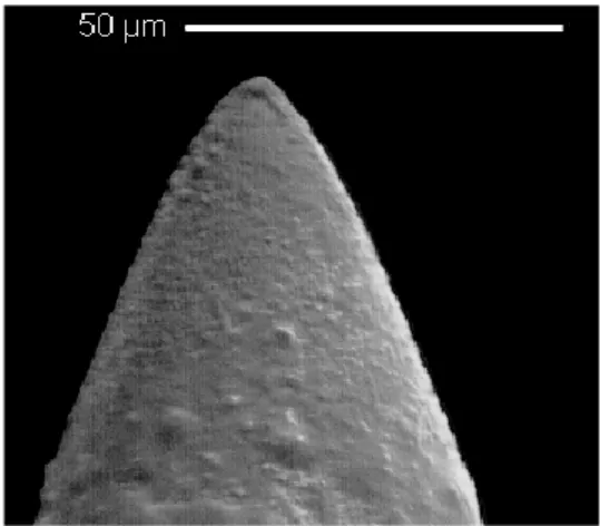
Fig. 1. REM image of an emitter needle.
2 The Double Star instrument 2.1 The ion emitters
As in all previous applications of this instrument, the ion emitters work on the principle of solid, needle-type liquid metal ion sources with Indium (isotopes with 115 amu and 113 amu to 96% and 4%, respectively) as charge material. A solid Tungsten needle with a tip radius between 2 and 5 µm (Fig. 1) is wetted by an Indium film and mounted in a reser-voir with the charge material, which is electrically heated to a temperature of >200◦C to melt the Indium (melting point at 156.6◦C). When a potential of 4 to 9 kV is applied between the needle and an extractor electrode, the electrostatic stress at the tip of the needle acts against the surface tension forces, and the liquid forms a sharp tip where the electric field be-comes high enough to initiate field emission (Fig. 2). An ion beam of about ±30◦Full Width Half Maximum (FWHM) is formed. The ion sources operate most efficiently in the cur-rent range below 100 µA. The advantages of these sources are not only their small mass and dimensions but also their high electrical efficiency. As little as 500 mg of Indium in a single reservoir can supply charge for several thousand hours of operation at 20 µA current, and apart from ∼0.5 W re-quired for the heater element, all electrical power goes into the beam.
2.2 The ion emitter modules
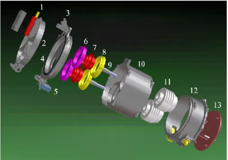
In order to extend the operating time of the instrument and to provide additional redundancy, the Double Star ASPOC instrument contains four individual emitters, which are oper-ated one at a time. Two emitters each are combined into a sin-gle housing (“module”) and powered by a common high volt-age supply. The selection of the operating emitter is purely based on heating the respective reservoir. The frozen Indium layer covering the needle of the cold emitter cannot form the sharp tip which allows field emission. Figure 3 shows an enhanced view of an emitter module.
Fig. 2. Schematic of an emitter needle. The overall length of the assembly is 19 mm.
The emitters are mounted in completely separate compart-ments with their individual extraction electrodes. This elimi-nates all possible paths for cross-sputtering from the active to the passive emitter. A common plate at the spacecraft body potential outside the extractor electrodes forms the interface to space. There is no focusing of the ion beam; the beam profile is determined by the emission characteristics of the tip and the extractor geometry. During storage and ground operations the emitters are held in a protective Argon atmo-sphere. The module is hermetically sealed until the cover is opened after launch by a pyrotechnic piston actuator which opens the clamp of the cover. At the rear end of the mod-ule there is a printed circuit board for the emitter selection circuitry.
2.3 Overall configuration
The Double Star ASPOC shown in Fig. 4 is a single unit con-sisting of an electronics box and two ion emitter modules. The instrument is mounted at the bottom side of the space-craft TC-1 by means of a bracket, such that the plate at the top of the instrument is at the surface of the spacecraft and is con-nected to its outer thermal blanket. The ion beam direction is antiparallel to the spin axis (see Fig. 5). The electronics are distributed over four printed circuit boards and a moth-erboard. The wall thickness of the box has been increased to 3.5 mm for the side panels and 5 mm for the top and bot-tom panels. The significant shielding effect against ionising radiation was useful to protect the electronics, because radia-tion hardened components, such as those used in the Cluster instruments, could not be used in Double Star due to trade restrictions. Additional spot shielding has been applied to a few critical components.
Fig. 3. Enhanced view of an emitter module. 1: pyrotechnic piston actuator, 2: protective cover, 3: clamp, 4: top ring with outer electrode, 5: microswitch, 6: isolator, 7: extractor electrode, 8: isolator, 9: ion emitter, 10: main housing, 11: thermal isolation, 12: electronics housing, 13: printed circuit board.
Fig. 4. The Double Star ASPOC unit.
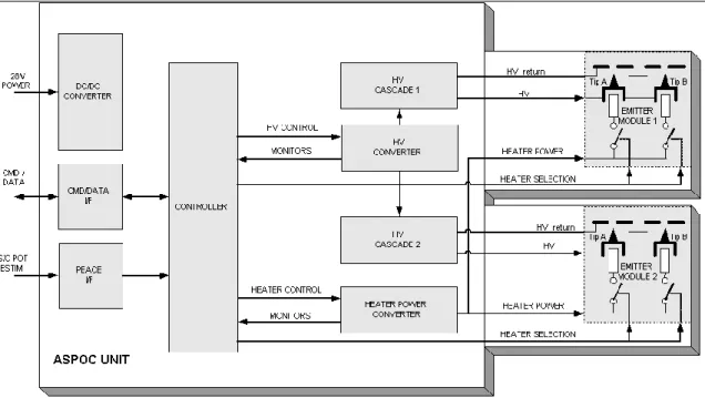
Figure 6 shows a block diagram of the electronics. The instrument uses an 80C85 microprocessor to control the high voltage and heater power for the emitters and to serve the in-terfaces to the Payload Data Management System and the electron spectrometer (PEACE), which can be configured to provide spacecraft potential values estimated from the
Fig. 5. Sketch of the accommodation of ASPOC and PEACE. Left: side view of spacecraft, spin axis points close to ZGSE, the ion
beam and the “look” directions of the 12 PEACE anodes are indi-cated. Right: bottom view of spacecraft, showing the positions of ASPOC and PEACE.
electron distribution function in real time. The flight soft-ware is stored in a bipolar PROM and copied into RAM at in-strument turn-on. A programmable gate array (FPGA) holds most of the logic circuits. The DPU includes a watchdog timer to reset the program in case of malfunction after a sin-gle event upset. However, no sinsin-gle event upsets or other radiation effects have actually been encountered in flight.
DC converters provide three fixed voltages (+5 V, +13.5 V, −5 V) and a variable output for the heater elements in the emitters. Each emitter module has its dedicated high volt-age cascade. The high voltvolt-age unit can power one of the two emitter modules at a time. A voltage and a current controlled
Fig. 6. Electric block diagram of Double Star ASPOC.
mode have been implemented. The voltage-controlled mode is used during start-up of an emitter, before ion emission sets in. As soon as some current is detected, the converter is switched into current-controlled mode in which a constant current is maintained. The voltage adjusts itself according to the operating conditions of the emitter needle in a range be-tween ∼4 kV and ∼9 kV. About 1.2 W of primary power is consumed by the DPU, and ∼0.8 W by heating one emitter. The remainder is used for high voltage, up to a maximum primary power of 2.9 W, depending on the emitted current.
2.4 Responsibilities
Design, manufacturing, test, and operation of the instrument is a joint effort of several institutions. Major responsibilities were taken by:
– Space Research Institute, Austrian Academy of Sci-ences for overall management, processor electronics, flight and test software, environmental testing, ground support equipment, and flight operations,
– Austrian Research Centers Seibersdorf for the ion emit-ters,
– Norwegian Defence Research Establishment (FFI) for the power converters for low voltage, high voltage, and heaters,
– ESA/ESTEC for the mechanical structure and mecha-nisms, elements of the ion emitter modules, and envi-ronmental testing,
– Center for Space Sciences and Applied Research (CSSAR) for test support.
Table 1. Instrument data summary.
Quantity Value
Mass
Electronics box 2100 g
2 emitter modules with covers 360 g
Harness 50 g
Flange for thermal blanket 30 g
Total 2540 g
Size
Electronics box 187×157×95 mm Emitter modules, closed 60 mm dia.×75 mm
Overall 187×157×170 mm
Power
Average power 2.5 W
Peak power 2.9 W
Telemetry rate 108 bit/s Design lifetime 16 000 h at 15 µA Beam characteristics
Species In+
Atomic mass 113, 115 amu
Energy ≈4 to 9 keV
Current max. 70 µA, design: 15 µA
Opening angle (half maximum) ±30◦
Direction antiparallel to spin axis
2.5 Instrument data summary
3 Cluster and Double Star TC-1 comparison
The instrument ASPOC on board the Cluster spacecraft has been described in detail elsewhere by Torkar et al. (2001). Many features of this predecessor instrument have been adopted, and some of its spare components were used. Some of the generally minor modifications have been mentioned above. The most interesting changes concern the ion beam and its effect on the spacecraft potential.
Ion beam characteristics – The ion emitters for Cluster in-cluded a focusing system for the beam which reduced the width to ±15◦ FWHM, whereas the instrument for TC-1 does not. As a result, the beam width increased to ±30◦ FWHM, which was completely acceptable for TC-1, as a sufficient free field of view was available. The absence of focusing electrodes reduces the risk for sputtering on inter-nal electrodes by the beam, and the difference between the current of the outgoing beam and the ion current leaving the tip is negligible, even at higher currents at least up to 50 µA. This reduces the variations of the outgoing beam current to a minimum and increases the usable output current range. Emitter design – Instead of four emitters, only two are com-bined into one module. The overall lifetime of 20 000 h at a15-µA average current remains compatible with the dura-tion of the Double Star mission in the nominal phase until mid 2005, but also including the extension phase until the end of 2006, if the operational pattern during the first year is maintained (see Sects. 4 and 5). The smaller number of emit-ters facilitates the manufacturing of the module and leaves enough space for a complete separation between the two ion optics. This measure prevents any cross-contamination be-tween emitters. A generally lower emission voltage has been achieved by careful selection of the needles, adjustment of the distance between the tip and the extractor, and the use of Zirconium for the Indium reservoir.
Electronics – Apart from the obvious changes due to the reduced number of emitters, some effort was taken to further protect all interfaces to the DPU against high voltage tran-sients by suppressor circuits. Since some previously used components, among them in particular the RAM and the FPGA, were not available for this mission, replacements had to be found. There is no double probe electric field instru-ment on board TC-1, and the electrical interface that had pro-vided on-board data of the spacecraft potential on the Cluster spacecraft, was removed for TC-1.
Software – The time resolution of the high voltage moni-tor was increased from 10 to 1 s. In the absence of an inter-face to a double probe instrument, the corresponding modes and logic were removed. The start-up sequence for an emitter was made more flexible by adding three parameters to deter-mine the temperature profile and the criterion for detection of beam ignition. The autonomous triggering of a one-minute duration emission at high current if a certain operating volt-age is exceeded – the so-called cleaning for an emitter – was modified as well.
Payload – The most relevant difference between the TC-1 and Cluster payloads for spacecraft potential control concerns the lack of a double probe electric field instrument on TC-1. Without direct measurements of the spacecraft po-tential one has to rely on estimates based on particle distri-bution functions. No other active experiments are present on TC-1 (neither an active sounder nor an electron beam instru-ment), which avoids disturbances of the spacecraft potential. Spacecraft – The modifications of the ion beam charac-teristics and the spacecraft configuration together determine the effect of ASPOC on the spacecraft potential in a given plasma environment. TC-1 is a smaller spacecraft than Clus-ter: 2.1-m diameter × 1.4 m, 16.2-m2surface, 2.94-m2 pro-jected area to the Sun, no wire booms. For comparison, the Cluster dimensions are: 2.9-m diameter × 1.3 m, 25.1-m2surface, 3.77-m2projected area to the Sun, and the satel-lites carry four probes with 80-mm diameter at the tip of wire booms of 44-m length. The projected area of TC-1, which determines the photoelectron current, is 22% smaller than for Cluster, neglecting ∼1 m2from the surface of the booms.
4 Overview of operations in 2004
The instrument ASPOC is part of the payload of the near-equatorial Double Star spacecraft TC-1 launched on 29 De-cember 2003. Operations in 2004 started with the commis-sioning of the instruments in several steps. On 5 January instrument power was turned on, with all housekeeping func-tions being nominal and the power consumption being 1.2 W. In the same session the functionality of the heater supply was successfully verified. The covers of both ion emitter mod-ules were opened by activating the pyros through the space-craft systems. Thereafter, the instrument was powered down. Commissioning of the high voltage units and the ion emit-ters started on 24 January after adequate time was left for outgassing. Between 24 and 28 January each high voltage chain was verified, and each ion emitter was operated at least twice to establish the individual parameters. Routine oper-ations of ASPOC began on 23 February 2004. A period of a few weeks followed, wherein the optimum ion current to control the spacecraft potential was established, based on re-sults from the electron spectrometer PEACE. During this pe-riod the instrument was activated for ∼7 h at a time, typically twice per orbit of 27.4 h. This time was also used to trim the operating parameters of the heaters, which are known to change moderately during the first weeks. Since April, AS-POC is operated outside the radiation belts on every second orbit. This operation is continuous (on the nightside) or di-vided into two parts between the radiation belts and the mag-netopause on some dayside orbits. However, even on dayside orbits ASPOC is sometimes commanded to also operate con-tinuously in the magnetosheath and occasionally in the solar wind.
ing commissioning. The results summarised in Table 2 were extremely satisfactory. All emitters operated at voltages be-low 6 kV, which leaves ample margin for possible future in-crease. The current efficiencies of all emitters were at 100%. During the first year of operation, typical ion currents were 10 µA and 15 µA, with some shorter intervals at 30 µA and 50 µA. Until 11 February 2005, 2670 h of operation with 39 150 µAh emitted charge (equivalent to an average ion cur-rent of 14.7 µA) were accumulated in 220 individual sessions (average session duration of 12 h). The average operating voltages were 5.4 kV at 10 µA and 5.7 kV at 15 µA. The ef-ficiency remained 100% throughout the first year of opera-tion: no leakage or other loss current in the emitter modules occurred.
6 Effect on low energy electron measurements 6.1 Introduction
Some results derived from the instrument ASPOC on board the Cluster spacecraft have been shown previously in litera-ture (e.g. Torkar et al., 2005a, b). These studies have demon-strated how ASPOC reduces very high positive spacecraft potentials and thereby improves the particle measurements. A similarly beneficial effect on the measurements of low en-ergy electrons can also be observed on Double Star TC-1. The analysis of the effect is, however, more difficult because of the lack of a direct measurement of the spacecraft poten-tial. The example shown in this work therefore highlights a different topic, ASPOC’s effect on electron measurements in the magnetosheath.
Without an electric field instrument the only indications for a change in the spacecraft potential can come from elec-tron or ion measurements at low energy. These effects are more readily detectable in electron data for two reasons. First, the lowest energy of the electron spectrometer PEACE on board TC-1 can be set to ≈1 eV, whereas the ion spec-trometer HIA starts at somewhat higher energy (≈5 eV/e). Secondly, the charged spacecraft attracts photoelectrons up to energies which roughly coincide with the spacecraft po-tential, causing distinct features in the spectrograms. In fact, a major objective for the spacecraft potential control lies in the suppression of photoelectron count rates in the electron spectra.
6.2 The instrument PEACE
The first results of spacecraft potential control on TC-1 will be shown through measurements of PEACE. The basic con-figuration of the ASPOC ion beam and the PEACE sensor viewing angles are shown in Fig. 5. The ion beam is emit-ted from the bottom side of the spacecraft antiparallel to its spin axis. The PEACE sensor is mounted on the mantle of the spacecraft with a radial field of view covering 180◦in the
Emitter A1 A2 B1 B2
Test dates (January 2004) 24 25, 27 25, 28 27, 28 Duration of start-up (min) 25 25 23 21 Steady state heater power (mW) 524 658 552 421 Ignition voltage (kV) 5.41 5.06 5.06 5.06 Operating voltage (kV) at 15 µA 5.65 5.18 4.51 4.31 Operating voltage at 25 µA 5.69 5.29 4.63 4.71 Operating voltage at 50 µA 5.92 5.53 5.06 5.72
polar direction and subdivided into twelve zones of 15◦
po-lar angle. Fazakerley et al. (2005) show the configuration in more detail. Anode number 0 receives electrons from “be-low”, i.e. moving nearly parallel to the northward pointing spin axis. Anodes 5 and 6 point almost radially outwards, and anode number 11 “sees” electrons from “above”. Most of the circumference of the spacecraft is covered by an in-dium tin oxide coating, and therefore electrically conductive solar arrays. The measurements presented here have been ob-tained in a range from ≈1 eV to 1.05 keV. The energy steps are roughly linearly spaced below ≈10 eV, and logarithmi-cally above. A 3-D distribution is observed every 4-s spin period, but a scheme which alternates between energy ranges is sometimes used. In this case a complete 3-D distribution over the full energy range is obtained every 8 s.
6.3 Sample spectrogram
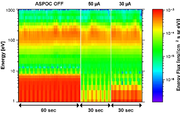
On 2 March 2004, shortly after 10:00 UT, the ASPOC ion beam was turned on to 50 µA for about 60 s. Thereafter the beam current was reduced to 30 µA. At that time the spacecraft was located inside the dayside magnetosheath (X=11.3 RE, Y=−0.12 RE, Z=−1.7 RE in GSE). Figure 7
shows electron spectrograms measured by PEACE, inte-grated over all viewing directions, in three parts over 60 or 30 s, respectively: without ion beam, and with a 50-µA and a 30-µA beam current. Clearly visible is the almost com-plete removal of photoelectrons from the bottom of the spec-trograms when the current is at 50 µA. Also at 30 µA, the reduction of fluxes at low energies is significant. The peaks observed at the spin rate are thought to comprise electrons produced in the analyser head by incident solar UV photons at times when sunlight can enter the collimator.
6.4 Spacecraft potential variations
Let us estimate the relative variation of the spacecraft po-tential when the beam current changes by looking at the en-ergy shift of the distribution function (the offset between the bold and thin lines shown in Fig. 8). Indeed, a numer-ical computation confirms this nearly constant energy shift (Fig. 9). From Fig. 8, the energy difference between each data point for high beam current and the corresponding line
Fig. 7. PEACE electron spectrograms on 2 March 2004, shortly after 10:00 UT, for different ASPOC ion beam currents.
Fig. 8. Electron distribution function for electrons nearly parallel (full lines) and antiparallel (dotted lines, in green) and perpendicular (full lines, in red) to the spacecraft axis; bold lines: with 50 µA beam current, thin lines: ASPOC off.
for zero current (interpolated for constant phase space den-sity, PSD) was calculated and plotted as a point in Fig. 9. For values of the phase space density where the curve is reasonably steep, in order to provide accurate results for this computation, the energy shift is about 3±1 eV, which suggests a similar reduction of the spacecraft potential by the ion beam operation. However, at higher energies (val-ues of the PSD <3×10⁻¹³m−6s−3)and at very low energy (PSD>10−11m−6s−3)the situation is less clear. The energy
Fig. 9. Energy shift between distributions functions of Fig. 7.
shift in the upward looking sensor (this is the direction oppo-site to the ion beam) shown in green symbols prevails and even increases for higher energies, whereas the “higher”-energy electrons from the downward looking sensor seem to be less affected by the changing spacecraft potential. Other influences very likely determine the electron flux at these en-ergies, and the calculated energy shift in this regime is not relevant. Possible error sources are variations of the ambient electrons (note that the spectrograms in Fig. 7 show small variations in the intensities), small inaccuracies due to the on-board data compression algorithm, or deviations of the real
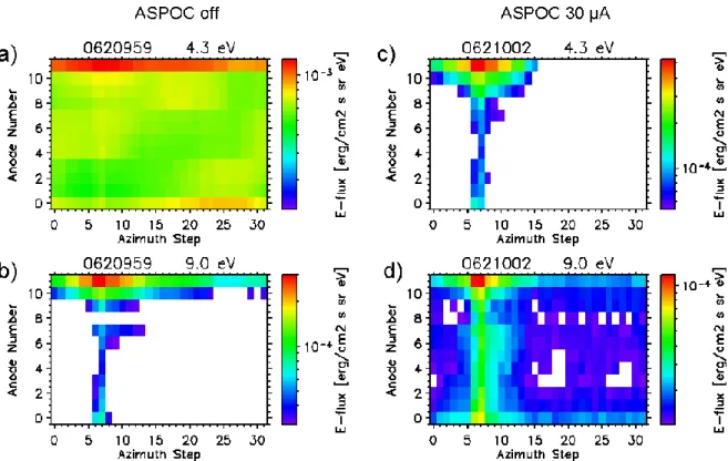
Fig. 10. Energy flux over azimuthal and polar angle at two energies, and for 0 and 30 µA ion beam current: (a) 4.3 eV, no ion beam, (b) 9.0 eV, no ion beam, (c) 4.3 eV, 30 µA ion beam, (d) 9.0 eV, 30 µA ion beam.
situation from the simple spherical geometry. The real ge-ometry is complicated not only by the shape of the spacecraft and the materials used in the vicinity of the sensors, but also by the presence of both a magnetic field and the ion beam. At very low energy, the high (photoelectron) fluxes measured before the ASPOC turn-on reach some plateau (thin lines at energies below 5 eV in Fig. 8), and the calculated change with the ASPOC-on case is too small. Finally, we compare the stable situation with a beam to a floating situation at a slightly different time, where the ambient plasma may have slightly changed. As a result, the calculated difference is not the same as the instantaneous effect. All these error sources may influence the electron distributions in subtle ways. The analysis of TC-1 data in this direction has only started, and a more accurate derivation of the energy shift is expected as one of the future results.
6.5 Absolute spacecraft potential
The determination of absolute values of the spacecraft poten-tial from electron data is even more difficult than for potenpoten-tial variations. Neglecting influences of a complicated geome-try and the magnetic field, one would assume – and models such as the one by Zhao et al. (1996) confirm this – that the spacecraft potential should appear in the measured electron distributions as a boundary between the photoelectron pop-ulation at low energy, which is trapped in the electric field of the sheath on the one hand, and the (accelerated) ambient
electron population at energies above the potential, on the other hand. In reality, the spacecraft potential should be in close relationship to this threshold energy. The practical dif-ficulty lies in the reliable determination of this energy. Visual inspection of colour spectrograms may be misleading, but a look at Fig. 7 suggests that the spacecraft potential may be at the energy where the spectrograms have yellow colour – half way between the (red) maximum at low energy and the (light green) minimum at higher energy, but below the mag-netosheath population near 100 eV. Using this method one would obtain 6–7 V when ASPOC is off, below ≈2.5 V with ASPOC at 50 µA and ≈3–4 V with ASPOC at 30 µA. More accurate results can be expected from the inspection of the phase space density data using plots similar to Figs. 8 and 9. One may ask which sensor’s data are most closely related to the spacecraft potential. In Fig. 10, which is discussed fur-ther below for ofur-ther reasons, panel (a) shows a case without an ion beam, and the upward looking sensor zone 11 deviates from all other zones. We conclude that some other effects which are unrelated to the ion beam have modified the re-sults for this direction, and we postpone the discussion as to whether the space charge of the ion beam “below” the space-craft (if there is any significant) would be able to modify the measurements, and in which way. In view of these unknowns we shall concentrate ourselves on other directions to find the absolute spacecraft potential.
In the downward looking sensor in Fig. 8 the difference be-tween the measurements with and without ion beam vanishes at energies above ≈9 eV (near PSD=3×10⁻¹⁴in Fig. 9). One might conclude that this corresponds to the uncontrolled po-tential, since above this energy no photoelectrons can be seen (neither with nor without ion beam), and the ambient electrons which are hotter than the photoelectrons (and there-fore have a smaller slope in the plot) dominate there. The spacecraft potential with a 50-µA beam current can be es-timated by subtracting the energy shift derived from Fig. 9 (3 eV) from this value of ≈9 eV.
6.6 3-D electron distribution
A very first attempt to study the 3-D electron distributions with their response to spacecraft potential control is illus-trated in Fig. 10, which shows the energy flux over azimuthal and polar angle at two energies (4.3 eV and 9.0 eV), and for a 30-µA ion beam current and without a 30-µA ion beam. The X axis spans 360◦in azimuthal angle in spacecraft
co-ordinates (with an arbitrary zero direction); the Y axis is the polar angle (anode number 0 is looking almost “downward” antiparallel to the spin axis, and anode 11 is looking almost “upward”). Panel (a) shows that the electrons measured at 4.3 eV and without ASPOC are almost uniformly distributed over azimuth, and have a strong component at high polar an-gle (zone 11) and some enhancement in zone 0. Zones 11 and 0 contain electrons with trajectories close to the space-craft surface. It is very likely that we see large fluxes of photoelectrons from these directions, and the asymmetry be-tween zones 11 and 0 is most likely due to different materials close to the sensor or a small differential charging. At 9.0 eV (panel b) an enhancement in one azimuthal direction appears, which corresponds to the Sun-looking direction. Note that the empty areas in the spectrogram do not contain zero count rates, but fall out of the flux range of 1:10 chosen for this pre-sentation for a better comparison between the panels. Again, electrons (presumably photoelectrons) from zone 11 domi-nate.
Panel (c), with electrons at 4.3 eV but measured when the ion beam was turned on at 30 µA, shows a high similarity to panel (b). This is consistent with the assumption that the spacecraft potential has been shifted by a few volts by turn-ing the ion beam on. Finally, panel (d), for 9.0 eV electrons in the presence of the 30-µA ion beam, still contains the peak at azimuth angles corresponding to the Sun, but the ratio be-tween maximum and minimum flux has decreased compared to panel (b) (from >10:1 to ≈10:1). This suggests that the earlier predominance of photoelectrons has disappeared and a large contribution of ambient electrons can already be mea-sured at this energy. In none of the panels for the 30-µA ion beam can one see any anomalous directional asymmetry. This is a further indication that the presence of the ion beam is not visible in the electron distributions other than by the advantageous effect of lowering the potential and improving the situation with the photoelectrons.
7 Conclusions
The instrument ASPOC on board the Double Star spacecraft TC-1 has inherited many features of the Cluster instruments. Some adaptations and further development work for the ion emitters and the electronics have been performed. The ion emitters perform very well and allow higher beam currents than on Cluster. The expected significant improvement of the low energy particle measurements on board can be ob-served. As there are no direct measurements of the space-craft potential on board, this has to be estimated based on models and on the energy spectrum of the electrons. It could be demonstrated that it is possible to determine the change in the potential due to the ion beam. The computation of the absolute value of the potential is more difficult and requires further analysis. The PEACE team is actively working on techniques for spacecraft potential assessment. Studies of the 3-D electron distributions have started and they confirm that the presence of the ion beam is not visible in the elec-tron distributions other than by the advantageous effect of lowering the potential and improving the situation with the photoelectrons.
Acknowledgements. The Double Star ASPOC investigation is sup-ported by ESA. The ASPOC team thanks the Chinese National Space Agency and the European Space Agency for the realisation of the Double Star Project. We thank Z. X. Liu and J. Wu for con-ceiving and leading this mission to a great success. We also thank the scientists and engineers of CSSAR, CAST, ESA, and Astrium for their extraordinar support of our instrument.
Topical Editor T. Pulkkinen thanks two referees for their help in evaluating this paper.
References
Escoubet, C. P., Pedersen, A., Schmidt, R., and Lindqvist, P.A.: Density in the magnetosphere inferred from ISEE 1 spacecraft potential, J. Geophys. Res., 102, 17 595–17 609, 1997.
Fazakerley, A. N., Carter, P. J., Watson, G., Spencer, A., Sun, Y. Q., Coker, J., Kataria, D. O., Fontaine, D., Liu, Z. X., Gilbert, L., He, L., Lahiff, A. D., Mihaljˇci´c, B., Szita, S., Taylor, M. G. G. T., Wilson, R. J., Dedieu, M., and Schwartz, S. J.: The Double Star plasma electron and current experiment, Ann. Geophys., 23, 2733–2756, 2005.
Laakso, H.: Variation of the spacecraft potential in the magneto-sphere, J. Atmos. Sol. Terr. Phys., 64, 1735–1744, 2002. Moore, T. E., Chappell, C. R., Chandler, M. O., Fields, S. A.,
Pol-lock, C. J., Reasoner, D. L., Young, D. T., Burch, J. L., Eaker, N., Waite Jr., J. H., McComas, D. J., Nordholdt, J. E., Thomsen, M. F., Berthelier, J. J., and Robson, R.: The Thermal Ion Dynamics Experiment and Plasma Source Instrument, Space Sci. Rev. 71, 409–458, 1995.
Mott-Smith, H. and Langmuir, I.: The theory of collectors in gaseous discharges, Phys. Rev., 28, 727–763, 1926.
Pedersen, A.: Solar wind and magnetosphere plasma diagnostics by spacecraft electrostatic potential measurements, Ann. Geophys., 13, 118–129, 1995,
SRef-ID: 1432-0576/ag/1995-13-118.
Riedler, W., Torkar, K., R¨udenauer, F., Fehringer, M., Pedersen, A., Schmidt, R., Grard, R. J. L., Arends, H., Narheim, B. T., Trøim,
Schmidt, R., Arends, H., Pedersen, A., R¨udenauer, F., Fehringer, M., Narheim, B. T., Svenes, K., Kvernsveen, K., Tsuruda, K., Mukai, T., Hayakawa, H., and Nakamura, M.: Results from ac-tive spacecraft potential control on the Geotail spacecraft, J. Geo-phys. Res., 100(A9), 17 253–17 259, 1995.
Thi´ebault, B., Hilgers, A., Forest, J., Escoubet, C. P., Fehringer, M., and Laakso, H.: Modelling of the photo-electron sheath around an active magnetospheric spacecraft, in: Proceedings of the 8th Spacecraft Charging Technology Conference, Huntsville, AL, USA, October 20–24, 2003.
Torkar, K., Riedler, W., Fehringer, M., R¨udenauer, F., Escoubet, C. P., Arends, H., Narheim, B. T., Svenes, K., McCarthy, M. P., Parks, G., Lin, R. P., and R`eme, H.: Spacecraft potential con-trol aboard Equator-S as a test for Cluster-II, Ann. Geophys., 17, 1582–1591, 1999,
SRef-ID: 1432-0576/ag/1999-17-1582.
stein, R., Olsen, R. C., Pedersen, A., Whipple, E., and Zhao, H.: Active spacecraft potential control for Cluster - implementation and first results, Ann. Geophys., 19, 1289–1302, 2001,
SRef-ID: 1432-0576/ag/2001-19-1289.
Torkar, K., Svenes, K. R., Fazakerley, A., Szita, S., R`eme, H., Dandouras, I., Fehringer, M., Escoubet, C. P., and Andr´e, M.: Improvement of plasma measurements onboard Cluster due to spacecraft potential control, Adv. Space Res., 33, in press, doi:10.1016/j.asr.2005.01.109, 2005a.
Torkar, K., Fehringer, M., Escoubet, C. P., Andr´e, M., Pedersen, A., Svenes, K. R., and D´ecr´eau, P. M. E.: Analysis of Cluster spacecraft potential during active control, Adv. Space Res., 33, in press, doi:10.1016/j.asr.2005.01.110, 2005b.
Zhao, H., Schmidt, R., Escoubet, C.P., Torkar, K., and Riedler, W.: Self-consistent determination of the electrostatic barrier due to photoelectron sheath near a spacecraft, J. Geophys. Res., 101, 15653-15659, 1996.