HAL Id: hal-02523146
https://hal.archives-ouvertes.fr/hal-02523146
Submitted on 31 Mar 2020
HAL is a multi-disciplinary open access
archive for the deposit and dissemination of
sci-entific research documents, whether they are
pub-lished or not. The documents may come from
teaching and research institutions in France or
abroad, or from public or private research centers.
L’archive ouverte pluridisciplinaire HAL, est
destinée au dépôt et à la diffusion de documents
scientifiques de niveau recherche, publiés ou non,
émanant des établissements d’enseignement et de
recherche français ou étrangers, des laboratoires
publics ou privés.
Design of static converters: an expert system approach
Djamel Fezzani, Hubert Piquet, Yvon Chéron, Michel Metz
To cite this version:
Djamel Fezzani, Hubert Piquet, Yvon Chéron, Michel Metz. Design of static converters: an expert
system approach. 5th European Conference on Power Electronics and Applications (EPE’93), Sep
1993, Brighton, United Kingdom. �hal-02523146�
DESIGN
OF
STATIC CONVERTERS:AN
EXPERT
SYSTEM
APPROACHD.
F e e
H.
Piquet,Y.
ChQonand
M. M e a .Laboratoire
d'Electmtscbnique et d'Electmnique IndushielleLIRA w
CNRS11'847
Toulouse, FRANCE.a
In order to design the structure of siatic OMLY~T(M a new .ppmacb is presented. Required s p e c i f i d a s are *bed by the wadomsd
ioplt and outpt vdiages and aments, which are expected to be gcncza(ed by the convata. These data are analysed byux
of design r u b and mthodr; it pennits t o i h t i f y the shwsed on the c o " m i o n ak, which themselves l u d to the syntbuirof
the switches: i & n N "of
the type (diode. thyrirtar,tnadrta
a dual thyrirtor). descriptiw of elaarical " a i n t s and f h g d e n . Rules and mcthodp are implemented00 a miao complter by we of 'expat system genentoi; the system utablishes the fusibility in the domain dthc d k c l convcxters and enables the use of these tools in the e d d m d- dedu&ous and used rules cdn be exhiihcd, making
this
software a powerful t d to help students un-ding the design muhodS.Kevwords.
S w i c converters, design. knowledgebased systems.I- INTRODUCTION
Thc
v n t study is a put o f a pmjcctf
a
the ruliwtion d a systemf
a
the c o wl i d e l duignof static cowenus. In ader tofulfil
theof
the Specifiatiala, the .imis
to detamine thetopologiul rtrueturc of the powu convener, to define its " n a n d
d
contd lawd
to* thedimnaiomqof*
componcnls.As
the "aw-how'
of&
designers is gencnlly exprwsed in tenn of rules. the system issh.pcd by
upe of a "knowkdge bssed systems".We
prwmt h a c the results of &is q r 0 . d in the domain of direct m n v u t m and point outthe i n t a w of
using h eto&
in the eduution domainn-
THE
KNOWLEDGEMODEL
Io this study, we omsider only the dLea convenas. Basically, these
Circuitr are only
conplosed
of swiwh, devoted to the conhvl of the p o w a flow b e e n a generator and a raceiva; this p a flow may be reversible.The
use of switch- to realise every connectiom toallow any power exchange bdween the input and the output leads to a
full bridge ~rmcture. compmed of four switches. These switches MC
coupled by pairs inside commutation cells (31 [I] [5]. The basic
s " e of these convutas is indicated in Fig. 1.
I
F i g m 1: direct converters.
This study is carried out under the following assumptias: voltage and current sourca are supposed perfect; switches are ideal in that they
commulate instantanmly and are considered as s h a t circuits in ON state and as opcn c i r ~ t s in OFF state.
To
fulfil the fundamcnt.l laws of interconneCti~n of souras (a cumnt soura cannot be openeed and a vohage s- cannu be shortswitches) is not allowed. These conmajots .IC defined by the
@on of the comD11D.tio. d s .
The
sauc~lre ddiocs an elcmmtary convater, which uwciate two switches d rcalisu the interconnection between a voltage source and a current soure Fig. 2).As
will be dwilledin II-2-3-
the @on of the switches in a axnmuwion cell have to be aomplemlaary 131.circuited). any combination (oorrcspondiog to Che mesof the
I
I
I I I
I
I
Figure 2: conunuhtion cell
In a commuta(ion cell, the Kirschoff laws are given by the following
eqUali0ns:
The dired static mnvaters, which assodate two "mutation cells.
can be considend as an interconnection matrix between a c u m n t scurce and a voltage source. ?he @idiom are described by
current and voltage waveforms
of
input and oulplt scurca. which arecxpeded to be generated by the converter. From that point of view, the
p.oblem is to h e r m i n e the charaderistics of the components of the
matrix.
111- DEFINITION OF THE KNOWLEDGE BASE
To solve this prcblem, a knowledge base has been & d u d fiom the analysis of the knowledge model; switches MC first considered as indcpcndeni components; in a second appro&. their behaviour is
analyzed, taking into account the constraints defined by the commutation all in which they take place.
We
consider thecommutation cell in two different operating mode: in a d y state, the analysis of the reversibilities of the source leads to the static
charaaaidcs of the switdrs; the analysis of the eaasient state 1 4
to the k a i p t i o n of their dynamic characteristics.
In-1- steady state d y s i s
Due to the assumptions conaaning the switches, these componmts have to be amsidered in coOtiouour rating
in
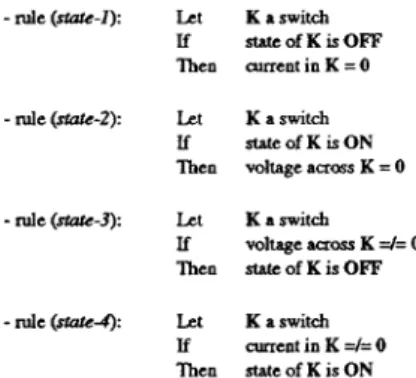
only O M of the followingstates: ON state oc OFF state. Simple rules an able to define the conditioar r e l d to these states and to assoeiatc them to the an~cnts
and the vohages of the switchu:
-
rule (sfub-1): Let K a switchIf statcofKisOF'F
Then current in K = 0
-
rule (sm-2): Let K a switchIf stateofKisON Then voltage amass K = 0
-
rule ( e - 3 ) : Let K a switchIf
Then stateofKisOFF voltage aum K =/= 0
-rule(szuted): Let Kaswitch
If currentinK=/=O Then state of K is O N
Let
a switch considcrcd as a dipole, acmrding to the r c f a e n a diredons desaibed 10 Fig.3.In
the (v&) p b C . the OpedUgdomain of a s w i t d ~ is defined by two branches: one is plaad on the (Vk = 0) &s and caresponds to the ON state; the ocher one is placed On the (Jk = 0) &S and is rsSOCiated With the OFF state; each O W of
thixc branches
is
eitha uni-directionnal or bidiredonnal.The s t u d y stale analysis enablcs to describe the ON state current and the OFF state voltage, according to the uni-diractionaal 01 bidLcctionnal w yof the voltage au0.w the voltage sour- and of the current in the a m e n t source, which are conneded to the commutation all. According to the reference conventions of Fig. 2, it can be p o i n d cut from the relations (1) and (2) that:
-
ifK1 is ON, then K1 is OFF and : J k l = J and V u = V. -if K2 is ON, thenK2
is OFFand :J u =
-J and Vkl = V.In t a m of d e s these conditions are e x p w e d as follows:
-
rule (reversibilify-1): the voltage reversibilities of the switches are the same as the voltage reversibility of the voltage sauce.- rule (reversibility-2): the current reversibilities of the switches are the same as the
current reversibility of the current
SOUICC.
As
a conclusion to the steady state analysis, it can be mentionned that the identificationof
the static characteristics of the switches UUI be achieved by the study of the rcversibilities of the sources. Thesecharac~ais(ics are made
of
two, three or four half axes of the thecoc+dinatc axes in the WkJk) plane.
111-2- TrPmient date .DpIysis
This chapter deals with the study of the 00mmuIafions; it analyzer the " i s m related to statc change of a switch i.e. the displaamnt of
its 0pa.ting point in the (V&) plane from a givm bma&
auoci.ted
with a given axis to .wther usociated with the perpendicular axis. The trajectory of the w a l i n g point desaibes the dynamical chanduistic of the consided switch.
Neglecting the stcood order phenomena such as reyerse currents, U
the switch is a dissipative component, the trajozkny of the OperabhB point must stay in the quadrants of the (Vk.Jk) plane whae:
v k J k > = o
Fig. 3 shows the voltage md c u m n t refezma conventions and the forbidden quadrants:
Jk
A
J
&
"k
I I
Figure 3: r e f m n a coovcntions and fmbidden quadrants
111-21- Type ofthe commotations
By comparison of the cumnt and the voltage related to a given switdI Wore and after its state change we can define if the arsOCirteed
ammutation is a tum-on "mucation or a turn-off canmutation. The following rules, gathaed in pairs which prcaca~t a redundancy with respec( to heir right side, but wich are different with rrsped to their left side, pamil the definition of the type of the commutation: -rule (tumdf-I): Let K a switch
If
v k bef- wm"mtati0n = 0And Then commutation
v k &er commutation =/= 0
the comm~tation is a tun-off
-rule (turn-@-2): Let K a switch
If
And then commutation Ik before commutation =/= 0 Ik after commUlaIiOn = 0&e commutation is a turn-off
-
rule (turn-on-I): Let K a switchIf
And VkP.fPuthecommu~on=O Tlen
commutation
Vk before the commutation =/= 0
the commutation is a tun-on
-
rule (tum-on-2): Let K a switchIf
Ik befOIC Commutation = 0And
Tben
commutation
Ik after the commutation =/= 0
-
the trajcday of the opcming point fdkwr the static d"U.
"2and the canmutatioo, whi& happena with minimal loslu ( n d with
respect to OUI asmptions) U rpwrumur.
It
Uche
only posaik solution when theopenring
point pruer fmm a given q w j n n t to the other one.-
the tnjcdayd
theopcnting
pointd m
nd follow the uis, mId stays in the same qwdnnt; the commtah '04 which is dissipative, must be mnaoued. This*
' 'onof
the d o nis
tmIlslatcd
in
tam of Nles as fdows:Fig. 4 shows S C V~"utation ~ fypes:
a d d
--off and tum- on (4.1 and 4.2); spont.nmur tun14 and tmn-on (4.3 and 4.4)4.1 contrdled turn-off 4.2 controlled tum-on
4.3 spoilt" turn-off 4.4 spontaneous mdo
Figure 4 : sevaal commutation cases
111-2-3- Conunutatiom imide a d
The f- rules consider the commutation from a local point of new. They do not take into aCCOUnt the fact that the switch- which they are related to operate inside a commrmtation cell.
Taking into account these coostraiats (expressed
in
terms of voltage and ament laws in equations (1) and (2)) luds to the conclusion that the switches of a comrrmtatioo all cannot turn on a tum offindependently. The two switches of a all must have complementary
commutations; following
NI-
are expressing fhis property:-rule ( w n q J l e ~ ~ - z ) : Let
cc
a co"ut.tion all If a s w i t & o f C C t " o nThen theocbcrswitchofCC
tltrns off
?he same reasoning concaning the (spontawnu a conaolled)
of
the commuudoar of thc Switcbw in accll
I s 0 1 4 s to aaomplcmcntlray property, as exprsscd in the following ruk:
-
~k
(wnp&menkzrydure): Let CC a "mutation a l lIf a r w i d o f C C k a con(mlkdmmrmtafi0n Thcn t h e o t h a r w i t c h o f c c h a s a p ~ c o m m u t a t i o n
-
Nk
(-1):-
Nk
(f3&2):
- mle
(KCLI):
- rule
(KCL2):
Ld
switcbcs and
V
its voltage source: CC a conumdation all,K 1 andK2
itsIf
lben
v u = v - v k l the V d U C Ofvk.
is
k n mLet
switchu and
V
its voltage xurceIf
CC a "nutation all, K1 and
K2
its the value ofv u
is knownlben
v k l = V - v ELet
CC a commutation cell, andK2
its switches and J its ament sourceIf
Then J E = J k l - J
the Value Of Jk1
is
k n mLet
switches and J its ament source
If
Then J k l = J u + J
CC a commutation all,K1 and
K2
its the value ofJ
u
is knownIV-
MODEL
FOR THE REASONING OFTHE
EXPERTThe previously desaibed set of
NI-
may be used by a h u m expertto rcalis the design of a static converter.
W e
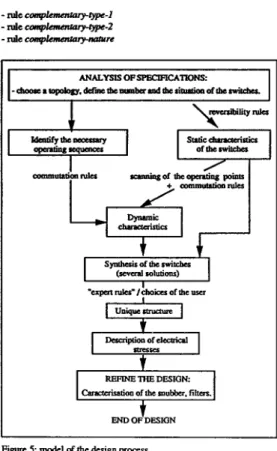
propo~e hac a model forthe design proms and we point out the most important steps. Each
stcp
of
the proass is asociated with an intcrmdiate result in the design and a subset of rules which enables to reach it. Fig. 5 shows this reasoning model.To determine a static convuter which
is
able to fuliil the specifiications, a human designer pr& several t a s k*
First. he analyses the spccdications and deduces the structure of theI
IU%lNE l H E DESIGN:
Figure 5 model
of
the design processAsecond h o d is to scan the displaament ofthe Opaating point of each swit& on its swic charactaistic at any time of the studied time iolerval. ?be previous selection of the operating sequa~cw is not n-: they am "discovered" during scanning. The deswhich are fired by that method are the previous commutation
NI-
which ensurethe complementary operation of the switches aod the
NI-
f a the idcntiiication of the type of the commumions:-
rule tum-off-I-rule tumdff-2
-
rule rum-on-I-
rule & m a r - 2This &go
-.
which uses the idemifiation d the staticdmnds&icr and the deteonidon
d
switching CpntiOn dou not lead to a unique lolutioo. Adding expat d e s (devoted to layad, for example) cuables a choice in the set of the possible dntimr. lhischoice keiq nude, the switches beeiDg compl&ly identified, the &go
is
contioued by the fouowing *:*
rynthcdsof
the switchw;identification of the wavdonns (current and voltage) related to Um
raritch;
UK
suhpetof NI=
which is used to achievethis
identiihtioo ComprirCs &e rukrfor
the aoalysk dswirch slated and the produ6ionrules:
-
d e rime-1 -ruleatute-2-
Nk St0fc;l -ntlcatute4 - r u l e K v G I-
ruleKYGZ
-rule K C L l-
d e KCL2V-
IMPUEMENTATIONlbepmcev w h i & b been desaibcd uses pneiaeand well defined
NI-
and lies on a deductive reasoning. 'Ibis kindof
knowkdgecould
beiq4emnted on a canplter by mean o f a druiul prognm, using language su& IS FORTRAN orC
NeveabeluJ adding rukr totranslate the
human
know-how. about layout foreumple,
would become daficulLIn
the aim of integrating into the f h l ryrtcmknowladgw devoccd to diffaent contexts the usc of "knowledge based
systemr"
has been Coosidaed.In
the educahd domaintbcse
systunr
whifh
d e r intaedng capabilities of explanation md which.IC able to exhibit their reasoning arc v a y intensting: this property
must confirm the idea that designing a convaim is not an intuitive a exhsuJtive proaess (identification
of
ye^ studied cases) bot is rcally theRsult ofa logical reasoning.
A module far the design of the dircct static anvaters
has bem
i m p l e ~ ~ ~ t e a by mclltl Of the KAPPA-Pc SO~IWU~ [l] [2].
The
knowledge model of the con- IS teen described a s a s e t o fobjects: sources (vdtage and current), co"utation cells induding
two s w i t c h [61
m.
Fig. 6 shows theSI&
used to define the ObpccSof the switch class.
ypdate E ~ A Slots Metitads
P a n n t h R o d
1
8
1
Figure
7:NIcKVL-J
U itis hm
bccn
impkmotcd in KAPPA-PCh
o.(unlthir
Nk Shdd be rud L1 fdlowr:~ ~
Let:
SWl
aswid,SWZ
a m i d , CCrammutrtion
allU:
SWI
and And If:the d u e ofthe vduge slot ofobjoct
SWl
is known
men:
tbe valueof
tk
vdrage slot of SWZis complced by tbe ruc hlduded in
4
hon:
(value
of
vduge slot of voltage scurceslot
of
cbpdcc)
(vdw of vdtage
SI&
of objcdSWl)
The
specitidions .redcccribcd
by meusa:
he
cntm tbe waveformswhich
arcupacrad
to be gcnaalcd ai iopa M d outpa of tbeawvcxia. For Um one
of
the four switches, the system gives thefollowing rwltr: voltage and ameat wavefarna. dunge and firing orders U any time in
tbe studied
in&.
These dah arc prescntcd lhmught the graphical USQ intafur U a set of-.
'Ibe system is shaped to reproduccu near as possibk themodel
of the design prooesc ofthe
human expat which has been presented in chap.Iv:
the design is splited into sub goalswich
ueAt
the d gkvel
the i n f u e n a d ewhich is selaclcd is the forward chaining: the system Consida the hown facts and fires therules which assumpfions are me, until it reachcs the ~ f l ~ e n t god
(urually the dunminatio n d the value of a given slot). The opaaiioo
of
ch
systcmis based on a loop which is madeof
two main step: adedsion step and an action SI-.
Thc
decision step includes che sckction of thc&hbk
NI-(ii
theU &r& ucme)
and thesquenlially.
choia done Nk among m e previous s&
At
the rctiooatep. mir N l eis
fired
and I new state of the infuena pmss is m e d (thevalueofa given slot is modified).
VI-
JEfAMF'LE-
APPLlCATlONS10.80
-1O.M
U U U
u u
u u u u
U U (*om
!
I
Figure 9: Jtstic charadcristic~ Of ~witcbes
K1
IKz
IK3
I Q .Fig. 10 b w s tbc r d t r of
the
analysis ofelectdcal
atMcs and theK1
Figure11:infamatre
Figure 12.: static . 'cdswitchK~
Switch K1 is a transistor with a diodc p l d
in
anti-parnlllbecplJe Of:
role ( f d o n - 4 ) whichstates:
U : t k S t a t i c ~ . 'cofaswitchbrr3bnodvs And If : thae
is
a conmUed turn-And
U
: thaeis
a conmUed turn-offAndU. thaeisaspontancousturwn And U: thae is aspontanwu turn-off
lhrn :the switch is a transista with a diode placed in anti- parallel
Fig= 1 2 b synthesis of K1
VII- CONCLUSION
A first application of knowledge based systems to thc deign in powa electronic is presented. Ita aim is to help in thc design d diroa static
COnVCltC€S.
This module hies to rcprcduce a model of the process d a human
designer. Its application domaim ace both rescad and education.
As
a design t o o l it is able to apply automatically and without a priori a set
d g ddes in any cue whae a d i e d mnyertcl is d e to
fulGl
the spc&iations.In the eduatiooal domain. as it manipdates e l e m n t q rules md
prcpores a rigourow appmach for
the .ynthwL
of a omvata itencourages the asshiation of LO improvced of design
REFERENCES
[l] F-
D.
(1992). "Sy&me exput parr la conception des convQlisK(1Ts statiques".Toulouse
[Z] Kappa-Pr (1991). refama manual and usa's guide
I31 Eoscignants
L.E.EI.
(1987). "Muhodes d ' h d e des convatisam statiqw".&&aQL
Paris141 L.auri&re J. (1987). "Intelligence aaifidelle: rhlution de probl&mes par lhomme d la machine".
E4amZlh
V I
Mopcy Y. (1982). "Mcthodes de sy- automatiqEdes convutisseurs statiquu; application
A
la &&e de nou-convatisseurs". ~ T o u l w s e . I61
CooJtnrCtiw".
Meycr
B.
(1988). "Object-orimted Sdtwarct71 Galloiiio J.F. (1988). "Transfext des
connaissances:
Sys4mscnpcas: techniques et methodes".