Publisher’s version / Version de l'éditeur:
Vous avez des questions? Nous pouvons vous aider. Pour communiquer directement avec un auteur, consultez la
première page de la revue dans laquelle son article a été publié afin de trouver ses coordonnées. Si vous n’arrivez pas à les repérer, communiquez avec nous à PublicationsArchive-ArchivesPublications@nrc-cnrc.gc.ca.
Questions? Contact the NRC Publications Archive team at
PublicationsArchive-ArchivesPublications@nrc-cnrc.gc.ca. If you wish to email the authors directly, please see the first page of the publication for their contact information.
https://publications-cnrc.canada.ca/fra/droits
L’accès à ce site Web et l’utilisation de son contenu sont assujettis aux conditions présentées dans le site
LISEZ CES CONDITIONS ATTENTIVEMENT AVANT D’UTILISER CE SITE WEB.
Internal Report (National Research Council of Canada. Institute for Research in Construction), 1994-11
READ THESE TERMS AND CONDITIONS CAREFULLY BEFORE USING THIS WEBSITE.
https://nrc-publications.canada.ca/eng/copyright
NRC Publications Archive Record / Notice des Archives des publications du CNRC :
https://nrc-publications.canada.ca/eng/view/object/?id=5635180f-fdf1-4c1d-9a02-cad004a70799 https://publications-cnrc.canada.ca/fra/voir/objet/?id=5635180f-fdf1-4c1d-9a02-cad004a70799
NRC Publications Archive
Archives des publications du CNRC
For the publisher’s version, please access the DOI link below./ Pour consulter la version de l’éditeur, utilisez le lien DOI ci-dessous.
https://doi.org/10.4224/20375611
Access and use of this website and the material on it are subject to the Terms and Conditions set forth at
Temperature Measurements in Fire Resistance Tests on Small-Scale,
Insulated and Non-Insulated, Regular Gypsum Board Assemblies
Sultan, M. A.; Denham, E. M. A.; Monette, R. C.; Morwick, D. W.
a+u
National Research Conseil national Council Canada de recherches CanadaInstitute for lnstitut de Research ~n recherche en Construct~on construct~on
nce Tests on Small-Scale,
lnsula ted and Non-lnsula ted, Regular
Gypsum Board Assemblies
Internal Report No. 671
Date of issue: November 1994
CISTI/ICIST NRC/CNRC Internaf report :
institute
--Bev Creighton ANALYSE
Received on: 12-15-94
ANALYZED
by M.A. Sultan, E.M.A. Denharn,
R.C.
Monette and D.W. MotwickThls IS an Internal report of the lnst~ture for Research ~n Construct~on Although not
ACKNOWLEDGMENTS
This research
is
a Joint Research Project among the following partners. The
National Research Council Canada (NRCC) appreciates the participation of these partners
in research, both in terms of their tinancial contributions and in tenns of their technical
contributions through the Project Steering Committee.
Canada Mortgage and Housing Corporation
Canadian Home Builders Association
Fiberglas Canada Ioc.
Roxul Inc.
CeUulose Insulation Manufacturers Association of Canada
Gypsum Manufacturers of Canada
Forintek Canada Corporation
Canadian Sheet Steel Building Institute
Institute for Research in Construction
TEMPERATUllE MEASUREMENTS IN FIRE RESISTANCE TESTS ON SMALL-SCALE, INSULATED AND NON-INSULATED. REGULAR GYPSUM
ABSTRACT
This report presents the tenlperature measurenlents from fire resistance tests conducted at the National Fire Laboratory (NFL) on insulated and non-insulated, small- scale, regular gypsum board protected asse~llblies. Assemblies studied were 2x2 (two layers of board on each of the exposed and unexposed sides) on wood and on lightweight steel studs. Three types of regular gypsurn board were studied: 7.82 kgIm2 without glass fibre in the gypsu111 board core, 7.35 kg/& with glass fibre in the gypsum board core and
7.27 kg/m2 w~thout glass fibre in the gypsum board core. The insulations used were glass,
mineral and cellulose (blown dry) fibres. The effect of using different insulations, type of
studs, different mass per unit area of gyp sun^ board and the presence of glass fibre in the
core of the gypsum board on the fire perfor~nance of small-scale wallboard assemblies
were addressed. The average temperatures on the unexposed surface, as well as on the inner-surfaces, are presented.
1 INTRODUCTION
A number of recent changes to the 1990 edition of the National Building Code of Canada (NBCC) and to CANICSA-A82.27-M91 Standard "Gypsum Board-Bullding Materials and Products" lnay have an effect on tlie fire perforlliance of insulated and non- insulated gypsum board assemblies. One of the major issues is that the requirement for weiglit per unit area for gypsurn board products has been removed. As well, there have
been changes in the NBCC to increase the so~uid trans~nission ratings (STC) between
dwelling units. These changes may have ail i~iipuct on the fire resistance of both wall and
floor assemblies referenced 111 Parts 3 and 9 of the NBCC, as well as the calculation
methods in Chapter 2 of the Supplemelit to the NBCC.
As a result of these changes, a Joint Researcli Project between IRCINRCC and 8
industry partners has been conducted with tlie primu~y objective of determining the
impact that the various changes to the codes and standards may have had on the fire
resistance ratings of insulated and non-insulated gypsu~ii board wall assemblies. A nuniber
of full-and s~iiall-scale tests 1i;ive been conducted to study the effect of different
parameters, such 21s tlie i~lsti~llation of resilient chilnnels, insulation in the wall cavity,
gypsu~ii board types and sy~ii~iietrical and ;tsymmetrical gypsurn board installations.
This report presents the results of 7 small-scale fire tests conducted at the National
Fire Laboratory, National Research C o ~ ~ n c i l Cnnada (NFLINRCC), as part of the joint
rese:lrch project to determine the effect of using different insulations; glass, mineral and
cell~~lose (dry application) fibre ill the wall cavity; wood or steel studs; reduction in mass
per unit area of regul~~r gypsum hoard and the presence of glass fibre in the gypsurn board
core on the fire perfoniiance of the assemblies. The 1-esults of the fire performance of the
small-scale asse~nhlies are analyzed and presented. Other reports will deal with other
issi~es in this project.
2 DESCI<IPTION OF
TEST
ASSEMBLIESThe small-scale test assembly fi~rciace set-up is shown in Figure I .
Seven assemblies were constructed 914 mm high by 914 tiiln wide by 141 lilm thick. The specific dimensions of each assembly are given in Figures 2 to 8.
2.2 Materials
Materials ~ised in the assemblies were as follows
2.2.1 G ~ S L I I I I Board
Regular gypsum bonrd conforming to the requirements of CSA standard CANICSA-A82.27-M91 [I] was used. Three type of regular gypsum board were
core (Assembly S-03); the second, low density regular gypsum board with glass fibre in
the gyps~1111 board core, has a ~ilass/u~lit area of 7.35 kg11112 (Assemblies S-01, S-02, S-32,
S-33 and S-34) and the third, low density regular gypsu111 board without glass fibre in the
gypsu111 board core, has a masslunit area of 7.27 kg11112 (Asse~nbly S-49). The thicknesses
of the gypsurii board used in the asselnblies was 12.7 l11m. Two layers of board were applied to each side of the studs.
2.2.2 Fr:lmine Materials
The steel studs used conformed to CGSB CANICGSB-7.1 [2] and the wood studs
were nominal 2x4s (38 111111 thick by 89 111111 deep) and conformed to CSA 0141-1970
131.
Three types of insulation were ~ ~ s e d in three assemblies; Glass Fibre-R12 (Supplied
by Fiberglass Canada Inc., Willowdale, Ontario with a mass per unit area of 1.08 kg/m2),
Mineral Fibre Roxul Plus-R13 (S~~pplied by Roxul Inc., Milton, Ontario and mass per unit
area of 2.78 kg+iz) :uid Celli~losic Fibre (Supplied by Thermo-Cell Insulation Ltd.,
Orleans, Ontarlo with a inass per unit awa of 4.57 kglmn2 and 5.25 kglmn2 for wood stud
and steel s t ~ ~ d assemblies respectively). All of the types of insulation used conform to
CSA-A101 [4]. Glass fibre insulation was used in Assenibly S-32; Mineral fibre insulation was used in Assembly S-33; and Cellulosic Fihre Insulation (dry application) was used in Asselnbly S-34.
2.3 Fabrication
The s11i:~ll-scale asse~iiblies were colistr~~cted using silllilac construction practices to
those eliiployed for fi~ll-scale fire test assemblies. All small-scale tests were non-load bearing.
2.3.1 Wood Stild Asselnblies
The wood studs ~ ~ s e d in Assemblies $02 and S-49 were 38 mm by 89 mm (SPF
No. 1 and No. 2, S-Dry, QLMA Mill Grade 149) spaced at 600 mil1 0.C. in Assembly
S-02 and spaced at 400 111111 0 . C . ill Asse~iibly S-49. TO make up the required furnace
width of 914 by 9 14 mni, an nddition:~l stud was added to each end (see Figure 3). The top and bottom plates were the11 added to complete the box assembly construction.
111 Assembly S-02, both the exposed and unexposed sides had two gypsum board layers: base and face layers. The base layer was attached to the wood studs with Type S
drywall screws, 41 I I ~ I U long sp~tced at 600 lllrn O.C. along the edges and in the field of
the hoard. Screw locations and gyps~1111 board joints are shown in Figure 9 [ 5 ] . The face
layer was attached to both the base layer and the studs with Type S drywall screws, 51
mat long spaced at 400 111111 0 . C along the edges and in the field of the board. Screw
heads on both the exposed 2nd ~~nexposed faces were covered with joint compound.
Gypsum board joints were taped and also covered with joint conlpound
111 Assembly S-49, both the exposed and unexposed sides had two gypsum board layers: base and face layers. The base layer was attached to the wood studs with Type S
drywall screws, 4 1 mm lolig spaced at 600 mm O.C. in the field of the board and along
the edges. Screw locations and gypsum board joints are shown in Figure 10 [5]. The Face
layer was attached to both the base layer and the s t ~ ~ d s with Type
S d~ywall
screws,51
heads on both the exposed and unexposed faces were covered with joint compound.
Gypsu~n board joints were taped and also covered with joint compound.
2.3.2 Steel Stud Assemblies
The steel studs used in Asse~nblies S-01, S-03, S-32 to S-34, S-46 and S-47 were
light C sections, 90 111111 by 30 mnl by 0.6 111111 thick and were spaced at 600 mm O.C.. T o
make up the required furnace width of 914 by 914 mm, an additional stud was added to
each end. The top 2nd botto~n runners were then added to complete the box assembly
co~istruction.
In the steel stud assemblies, both the exposed and unexposed sides had two
gypsu~ll board layers: base and face layers. The base layer was attached to the studs with
Type S drywall screws 25 mm long spaced at 300 mm O.C. along the edges and spaced at 600 mrn O.C. in the field of the board. Screw locations and gypsum board joints are
shown in Fig~lre 1 1 [5]. The face layer was attached to both the base layer and the studs
with Type S drywall screws 41 m m long spaced at 300 1nm O.C. along the edges and in
the field of the board. Screw heads on both the exposed and unexposed faces were
covered with joint coinpound. Gypsti~n board joints were taped and also covered with
joint c o m p o ~ ~ n d . 2.3.3 Insulation
Mineral fibre and Glass fibre lbatts were 90 111111 thick by 615 mm wide by 1220 mm
long. The Cell~~losic fibre insulntion was blown into the cavity (blind fill), after the
installation of the ther~nocouples.
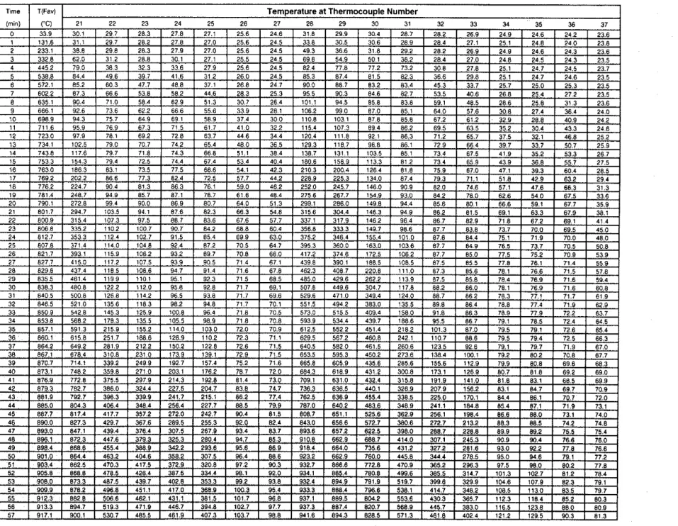
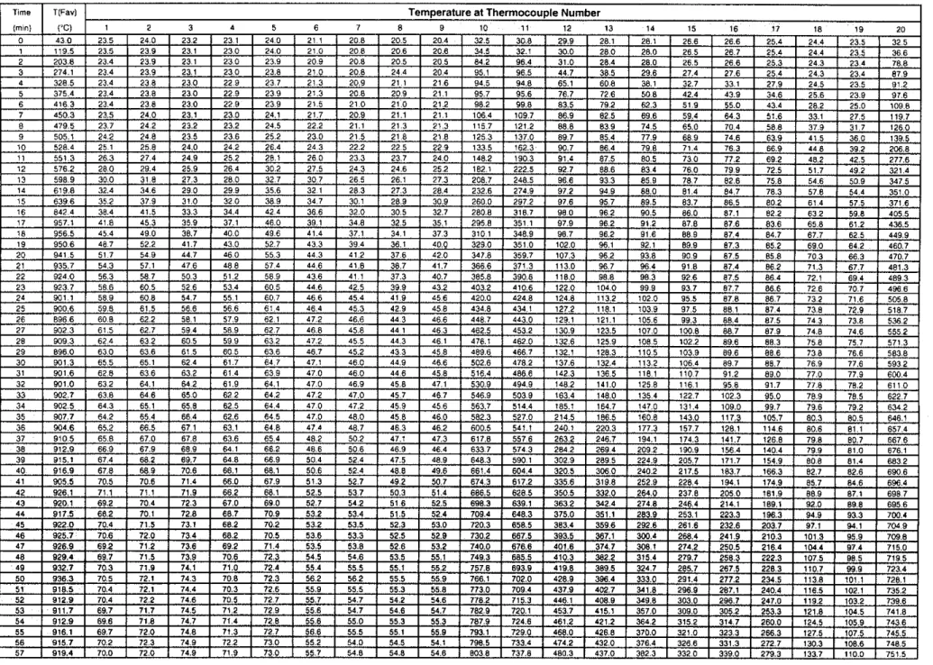
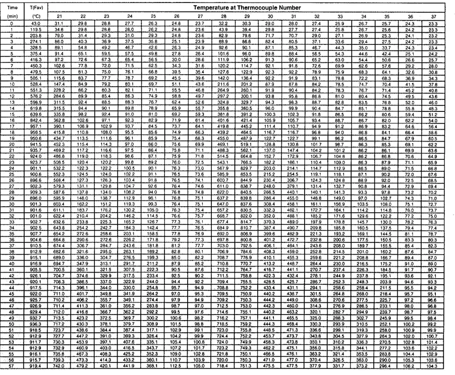
2.4 Instrumentation
Type K (20 gauge) chro~nel-ulumel thermoco~iples, with a thickness of 0.91 mm,
were ~ised for measuring temperatures at ;I ~ l u ~ n b e r of locations throughout each assembly.
Inside the cavities, the ther~iiocot~ples were attached to 2 wire hangers, installed midway
between the st~lds i111d :it ~ n i d depth of the studs, at distances of 114 and 314 of the height
of the wall. By providing tension to the hanger wire, the ther~i~ocouples were positioned
flush with the surface of the wallboard.
Ther~nocouples located on st~1d1wallbo:rrd faces and those located between
wallboal-d layers were taped into position and then the wallboard was screwed to the stud or the face wallboarci layer.
A number of small holes, 12.7 l n ~ n diameter, were ddrled through the wood studs
at the bottoln of Assemblies S-02 and S-49 to allow the ther~liocouple wiring to exit the
assembly.
Thermoco~~ple locations are shown for each assembly in Figures 2 to 8.
Thermoco~lple locations on the unexposed s ~ ~ r f i ~ c e for all asse~nblies are shown in
3 TEST APPARATUS
The tests were carried out by exposing the assemblies to heat in a propane-heated, fm brick lined vertical furnace with an 810 by 810 mm opening. The assemblies were sealed at the edges against the furnace with ceramic fibre blanket The furnace temperature was measured by two 20 gauge shielded thermocouples, located near the vertical centreline of the furnace and 300 mm back from the exposed surface of the assembly. The average of the two thermocouple temperatures was used to control the furnace temperature.
4 TEST CONDITIONS AND PROCEDURES 4.1 Fire Exposure
The ambient temperature at the start of each test was approximately 2 2 ' ~ . During the test, the wall assembly was exposed to heating on the exposed side, in such a way that
the average temperature in the furnace followed as closely
as
possible theCANAJLC-S101 [6] standard temperature-time curve.
4.2 Failure Criteria
The failure criteria for the small-scale tests were derived from CANIULC-S101-
M89 [6]. The assembly was considered to have failed if a single point thermocouple
temperature reading on the unexposed face rose above 18OoC or the average temperature of the 5 thermocouples readings under the insulated pads on the unexposed face
rose 140°C above the ambient temperature or there was passage of flame or gasses hot enough to ignite cotton waste. The tests were run beyond the failure temperatures referred to above to provide additional performance data.
4.3 Recording of Results
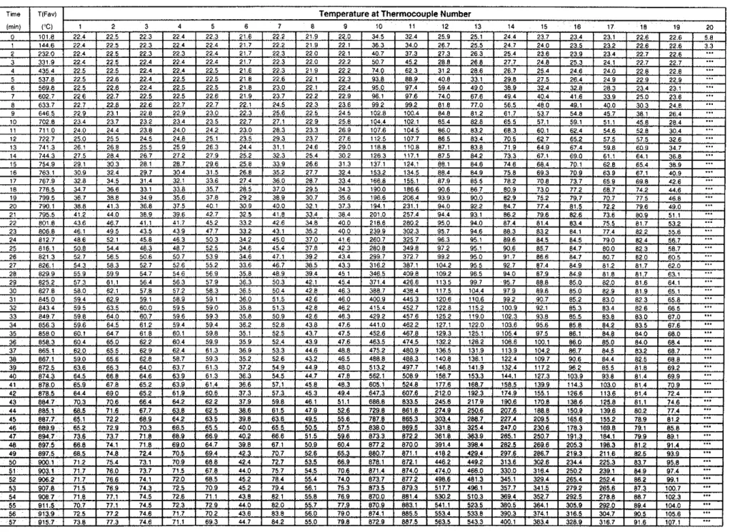
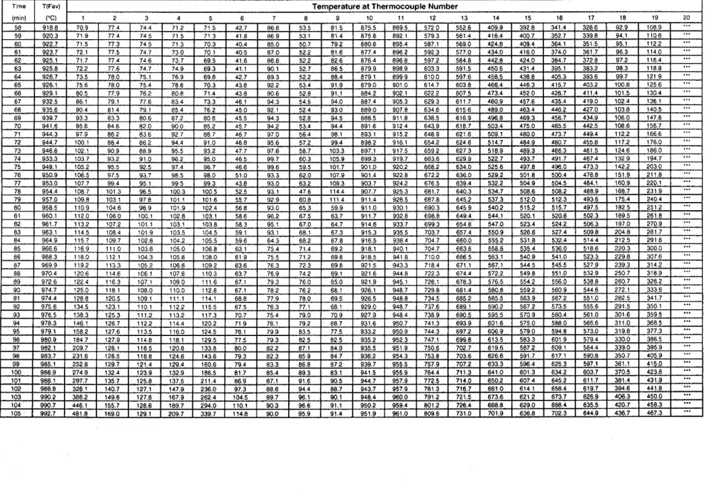
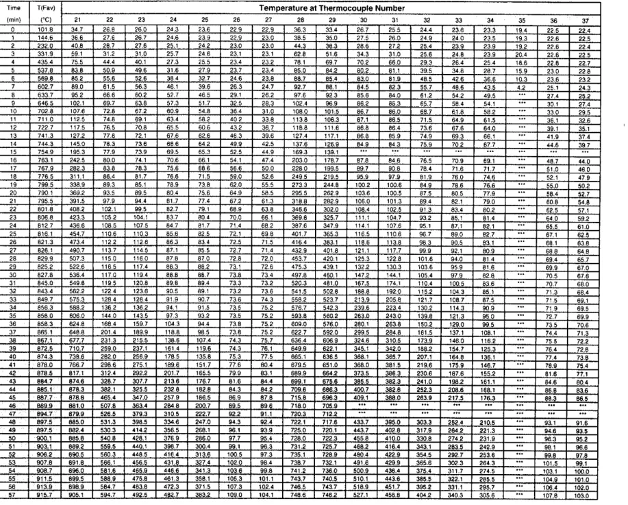
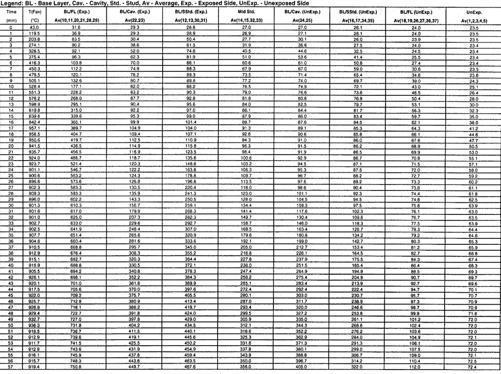
The furnace and wall assembly temperatures were recorded at 1 minute intervals using LABTECH NOTEBOOK data acquisition software and a Fluke Helios-I data acquisition system. Individual thermocouple values and average furnace temperature values as well as the average surface temperature values for the 7 assemblies are listed in Tables 1 to 14.
5
KESULTS
AND DISCUSSIONThe results of the 7 small-scale fire tests are summarized in Table 15 in which the
single point and average failure times are given for each assembly.
The average surface and inner-surface temperature distributions recorded
throughout the tests are plotted in Figures 13 to 20. Detailed temperature distributions for
all
five thermocouples under the insulated pads on the unexposed surface are also plottedFire Performance of Insulated Small-Scale Assemblies
The fire performance of insulated and non-insulated small-scale assemblies is
shown in Figure 20.
Glass Fibre Insulation
-
Tests S-32 and S-01 were carried out to investigate the effect of the installation of glass fibre insulation (GFI) in a wall cavity on the fue performance of double layer (2x3, regular light gypsum board, small-scale wall assemblies. Thetemperature failure criterion was reached at 74 min for Test S-32 and at 82 min for Test S-01. These results suggest that, in small-scale, double layer, regular light gypsum, assemblies, the glass fibre insulation has a negative effect on the fue resistance performance compared to a non-insulated assembly.
With the small-scale tests, failure is predominantly due to heat transfer through the gypsum board layers. With the glass fibre insulation in the wall cavity, there is a more rapid temperature increase in the gypsum board on the fue-exposed side. As a result, the raie of calcination of the regular gypsum board increases and causes premature
failure/solitting of the gvusum layers on the fm-exoosed side and melting of the insulation. This the; spee3s up thG-iate of heat transfer through the layers of the assembly causing premature failure of the assembly.
Mineral Fibre Insulation
-
Tests S-33 and S-01 were conducted to investigate the effect of the installation of mineral fibre insulation (MFI) in the wall cavity on the f i eperformance of double layer, regular light gypsum board, small-scale wall assemblies. The temperature failure criterion was reached at 98 min for Test S-33 and at 82 min for Test S-01. These results suggest that, in small-scale double layer assemblies with 40 mm thick mineral fibre insulation in the wall cavity, the addition of mineral fibre generally has a positive effect on the fue resistance performance compared to the baseline Assembly S-01.
Cellulose Fibre Insulation
-
Tests S-34 and S-01 were conducted to investigate the effect of the installation of cellulose fibre insulation (CFI) in the wall cavity on the f i e performance of double layer, regular light gypsum board, small-scale wall assemblies. The temperature failure criterion was reached at 102 min for Test S-34 and at 82 rnin for Test S-01. These results suggest that, in small-scale, double layer, regular light gypsum board, assemblies with 90 mm thick cellulose fibre insulation in the wall cavity, the addition ofcellulose fibre insulation (blown
dry)
has a positive effect on the fue resistanceperformance compared to the baseline Assembly S-01.
Fire Performance of Wood and Steel Studs Non-Insulated Small-Scale Assemblies
Tests S-02 (wood stud) and S-01 (steel stud) were carried out to investigate the
effect of stud type on the fire performance of double layer, regular light gypsum board, small-scale wall assemblies. The temperature failure criterion was reached at 88 min for Test S-02 and at 82 min for Test S-01. These results suggest that, in small-scale, double
regular light gypsum board assemblies, the fire resistance performance of assemblies with
wood studs is slightly higher than assemblies with steel studs.
Fire Performance Regular Gypsum Board with Different MassKJnit Area in Non- Insulated Small-Scale Assemblies
Tests S-03 ( 7.82 kg/m2) and S-01 ( 7.35 kg/m2) were conducted to investigate the
performance of double layer small-scale gypsum board wall assemblies. The temperature failure criterion was reached at 104 min for Test S-03 and at 82 min for Test S-01. These results, as shown in Figure 20, suggest that, in small-scale, double regular gypsum board layer assemblies, the reduction in the masdunit area caused a negative effect on the fire resistance performance.
Fire Performance of Light Weight Gypsum Board with and without Glass Fibre in the Gypsum Board Core (Non-insulated Small-Scale Assemblies)
Tests S-01 and S-49 were carried out to investigate the effect of the presence of glass fibre in the gypsum board core on the fire preformance of double layer gypsum board on steel stud, small-scale assemblies. Assembly S-01 was regular low density gypsum board with glass fibre in the gypsum board and a masdunit area of 7.35 kglm2. Assembly S-49 contained low density regular gypsum board without glass fibre in the gypsum board and had a masdunit area of 7.27 kg/m2. The temperature failure criterion was reached at
87 rnin for Test S-49 (no glass fibre in gysum core) and at 88 rnin for Test S-02 (with
glass fibre in the gypsum board core). These results, as shown in Figure 22, suggest that, in small-scale double layer assemblies, the presence of glass fibre in light weight gypsum board did not show an effect on the fire performance.
REFERENCES
1. CANICSA-A82.27-M91, Gypsum Board-Building Materials and Products.
Canadian Standards Association, Rexdaie, Ontario, 1991.
2. CANICGSB-7.1-M86, Cold Formed Steel Framing Components. Canadian
General Standards Board, Ottawa, Ontario, 1986.
3. CSA 014 1-1970, Softwood Lumber, Canadian Standards Association, Rexdale,
Ontario, 1970.
4. CSA-A101-M83, Ther~nal Insulation, Canadian Standards Association, Rexdale,
Ontario, 1983.
5 . CANICSA-A82.3 I-M91, GYPSUIII Board Application, Canadian Standards
Association, Rexdale, Ontario, I99 I .
6 . CANIULC-S 101-M89, Standard Methods of Fire Endurance Tests of Building
Constr~~ctio~l and Materials. Underwriters Laboratories of Canada,
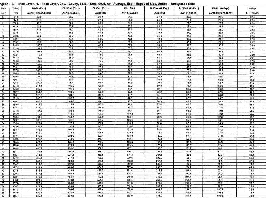
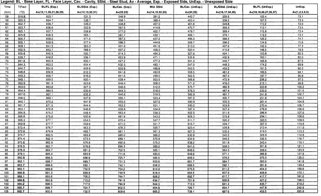
Table 2. Average Temper-atures Measured in Assembly S-01, Steel Stud, 2x2 Gypsum Board Layers, No Resilient Channels (Cant.)
Legend: BL
-
Base Layer. FL-
Face Layer, Cav. -Cavity, SStd. -Steel Stud, Av-
Average, Exp.-
Exposed Side, UnExp.-
Unexposed SideTable 4. Average Temperatures Measured in Assembly S-02, Wood Stud, 2x2 Gypsum Board Layers, No Insulation (Cont.)
Legend: EL
-
Base Layer, FL-
Face Layer, Cav.-
Cavity, SStd.-
Steel Stud, Av-
Average, Exp.-
Exposed Side, UnExp.-
Unexposed SideTable 5 . Temperatures Measured in Assembly S-03, Steel Stud, 2x2 Gypsum Board Layers, No Insulation (Cont.)
Table 6. Average Temperatures Measured in Assembly S-03, Steel Stud, 2x2 Gypsum Board Layers, No Insulation
Legend: EL
-
Base L a y e r , C a v .-
C a v i t y , Std. - S t u d , Av-
A v e r a g e . E x p .-
Exposed Side, U n E x p .-
U n e x p o s e d Side (miniTime T(Fav1 BUFL (Exp.) BUCav. (ESP.) BUSSId. (Exp.)
0 I 43.0 I 31.6 1 29 3 1 26.8 1 27.0 1 27.0
I
26.1 I 11 ..-.
.-"
""-
""" """ "- . ~24.0
- . . 23.5 -~ ~
(a) Av(lo.ll,20,21,28.29) Av(22.23) Av(12,13,30,3I) Ar(14.15.32.33) Av(24.25) Mld Std.
Au~16,17.34,35)
BUCav. (UnExp.) Bvsstd. (UnExp.) B W L (UnExp.) UnExp. Av(l8,19.26.n,36,37) Av(1,2,3,4,5)
Table 6. Average Temperatures Measured in Assembly S-03, Steel Stud, 2x2 Gypsum Board Layers, No Insulation (Cont.)
Legend: BL
-
Base Layer, Cav.-
Cavity, Std.-
Stud, Av-
Average, Exp.-
Exposed Side. UnExp.-
Unexposed SideTable 8. Average Temperatures Measured in Assembly S-32, Steel Stud, 2x2 Gypsum Board Layers, Glass Fibre Insulation
Table 14. Average Temperatures Measured in Assembly S-49, Wood Stud,
2x2
Gypsum Board Layers, No Insulation Legend: BL-
Base Layer, FL-
Face Layer, Cav.-
Cavity. Std.-
Stud, Av-
Average, Exp.-
Exposed Slde, UnExp.. Unexposed SideTable 14. Average Temperatures Measured in Assembly S-49, Wood Stud, 2x2 Gypsum Board Layers, No Insulation (Cont.)
Legend: BL
-
Base Layer, FL-
Face Layer, Cav.-
Cavlty, Std.. Stud, Av.
Average, Exp.-
Exposed Slde, UnExp.-
Unexposed SideTable 15. Small-Scale Assembly Parameters and Fire Test Results
Type Thickness Channel Failure Failure
RL
-
Low Density Regulor Gypsum Boord with gloss fibre in Gypsum Boord (7.35 kg/mZ)RL'
-
Low Density Regular Gypsum Board, no gloss fibre in Gypsum Board (7.27 kg/m2)RH -Regular Gypsum Board. no gloss fibre in Gypsum Boord (7.82 kg/m2)
GF - Glass Fibre lnsulotion
MF
-
Mineral Fibre InsulationCFi
-
Cellulosic Fibre Insulation (blown dry)Stal Studs
Unexposed
Side
/-=-
600 rnrn-d
914 rnrn
Drawing Not To Scale
682 rnrn
232 rnrn
1
Fire
Exposed
Side
.m Sl3:
-
-
-
72 23-6
24 89 rnrn P-
-
2a 29 32 s3 % 37Unexposed
Side
Drawing Not To Scale
Fire
Exposed Side
f
Facing bd 10 Steel StudsUnexposed Side
I I I I II
I
I
I
I
I
I
I
I
I
I
I I I II
I
I
I
I
914 rnmI
I
I
I I II
II
II
I
I
I I I II
II
I
I
111
21 682 rnm ' 5 , t;; I I I 1sI
I
I
I
I I I I I I I IDrowing Not To Scole
Fire Exposed Side
r
Gypsum Facing BoardUnexposed Side
Drawing Not To Scale
Fire Exposed Side
Gypsum Board
r
Facingm
Stcei Studs
Mineral Fibre Insulation
Unexposed Side
Drawing Not To Scale
682 rnrn
-7
232 rnm
Fire Exposed Side
Unexposed Side
I
301.;:
1
z
/ I
I::
I",
I
I
I
I
I
914 mm I II
I I II
II
Ik
-
914 rnm4
-
~
Drawing Not To Scole
Fire Exposed
Side
w 26 YI 31%
-
la $9 22 U 20 24 89 rnrn 'q 25 w 32 38 w u -~ nUnexposed
Side
914 mrnDrawing Not To Scale
Fire Exposed Side
600 rnrn I
A
89 rnrn
Base Layer 7
Face Layer
-~
Unexposed Side7
(a) Base Layer (a) Base Layer
600 rnrn
-4
600 rnrn914 rnrn
Gypsum Board Joint
(b) Face Layer
600 rnrn
h
1
600 rnrn'Gypsum Board Joint
(b) Face Layer
600 rnrn
k
(i)
Fire Exposed Side
(ii)
Unexposed Side
Drawing not to scale
Figure 9. Screw Locations for 600 rnrn O.C. Wood Stud, 2x2 Regular
Fire Exposed Side
W
B
89 m mBase Layer
7
Face Layer
Unexposed Side
(a) Base Layer (a) Base Layer
4
400 m m Gypsum Board Joint914 m m 600 mrn 600 m m
4
4
(b) Face Layer Joint (b) Face Layer(i)
Fire
Exposed
Side
(ii) Unexposed
Side
Drawing not to scale
Figure 10. Screw Locations for 400 mm O.C. Wood Stud, 1 x2 Regular
Fire Exposed Side
b-
600 rnrn---ef
C
I[
90 rnrnBase Loyer
Face Layer Unexposed S d e
(a) Base Layer (a) Base Layer
600 rnrn 600 rnrn Gypsum Board J o i n t 1 (b) Face Loyer
-4
600 rnrn 600 rnrn 914 rnrn.
.
91 4 rnrnLGypsurn Board Joint
(b) Face Loyer
600 rnrn
to-
1-
914 rnrn4
(i) Fire Exposed Side
(ii) Unexposed Side
Drawing not t o scale
300 rnrn
Figure 11. Screw Locations for 600 mm O.C. Steel Stud, 2x2 Regular
Gypsum Board Layers, Small-Scale Assemblies S-01, S-03, 5-32 to S-34
Thermocouple Under
Std. ULC/S101
Insulated Pad
x Bare Thermocouple
Drawing not to scale
Figure 12. Thermocouple Locations on Unexposed Surface
(a) Average Face Temperature Distribution
1000 -
Average Values-
-
ULC Furnace Temp.-
_ _ _ - - -
-- -
_ _ _ - _ - - -
BLFL (Exp.)-
--- BUSStd. (Exp.) BUCav. (Exp.) ... Mid SStd.-
BUCav. (UnExp.) --- BUSStd. (UnExp.)-
-
BUFL (UnExp.)-
-
UnExp. Failure Criterion 1-
(Rm. Temp.+
l39'C) ' 1 1 , , 1 , , , 1 1 1 1 1 , , , 1 , , , 1 , , ,0
20
40
60
80
1 00
120
140
1 60
Time (min.)
-
-
(b) Unexposed Temperature Distribution Unexposed Face
-
Thermocouple 1-
. - - Thermocouple 2-
"
-
400 -
.-... Thermocouple 3-
2
-
-- Thermocouple 4-
s-
-
... Thermocouple 5-
?!
a, n-
200
Failure Criterion 2r-"
(Rm. Temp.+
l80'C)-
0
1 1 1 r 1 1 1 1 1 1 1 1 1 , , , 1 , , , 1 , , , 1 , , ,0
20
40
60
80
100
120
140
160
Time (min.)
-
(a) Average Face Temperature Distribution Average Values1000
--
-
ULC Furnace Temp.-
-- - -
BUFL (Exp.) ... BLNStd. (Exp.)-
--
BUCav. (Em.) ... . ... .. Mid WStd.-
BUCav. (UnExp.) --- B M S t d . (UnExp.)-
-
-
BUFL (UnExp.)- -
UnExp. Failure Criterion 1-
(Rm. Temp. + 139'C)1
l l l l l l l l l l l l r0
20
40
60
80
100
120
1 40
160
Time (min.)
0
0
20
40
60
80
100
120
1 40
160
Time (min.)
(b) Unexposed Temperature Distribution Unexposed Face
.
- -
Thermocouple 2... Thermocouple 3
Failure Criterion 2 (Rm. Temp.
+
l8VC)0
0
20
40
60
80
100
120
140
160
Time (min.)
I " ' ~ b " I ' c ' I " r I ' ~ ~ I ' J ~ I ~ ~ ~
(a) Average Face Temperature Distribution Average Values -
.
-
ULC Furnace Temp.-
-
-
- - - BUFL (Exp.) ... BUSStd. (Exp.)-
.- BUCav. (Em.) - BUCav. (UnExp.) ..-.- BUSStd. (UnExp.)-
-
BUFL (UnExp.) Failure Criterion 1-
(Rm. Temp.+
139'C) .- - -
1 1 1 1 1 1 1 1 1 1 , 1 1 1 1 , 1 1 1 1 I , , ,0
0
20
40
60
80
100
120
140
160
Time (min.)
1 " ' 1 1 " 1 " ' 1 " ' 1 " ' 1 " ' 1 " '(b) Unexposed Temperature Distribution Unexposed Face
-
Thermocouple 1 . - - Thermocouple 2-
-
.---. Thermocouple 3-
-
Thermocouple 4-
... ... ... .-
Thermocouple 5-
-
I
Failure Criterion 2-
(Rm. Temp.+
180'C)-
-
-
(a) Average Face Temperature Distribution Average Vdues
1000 -
-
- ULC Furnace Temp.-
-
. . -
-
BLFL (Exp.) --- BUSStd. (Em.)-
--
BUCav. (Exp.) ... Mid SStd. - BUCav. (UnExp.) ..-.- BUSStd. (UnExp.)-
-
BUFL (UnExp.)- -
UnExp. Failure Criterion 1-
(Rm.Temp.+139'C)-
I I 1 I I S I I0
20
40
60
80
100
120
Time (min.)
0
0
20
40
60
80
100
120
Time (min.)
Figure
16.
Temperature Distributions For Small Scale Test Assembly
S-32
1 " ' 1 ' 1 ' 1 " ' 1 " ' 1 " '
-
(b) Unexposed Temperature Distribution Unexposed Face
-
-
Thermocouple 1 - - - Thermocouple 2-
-
-
... Thermocouple 3-
-Thermocouple 4-
... Thermocouple 5-
Failure Criterion 2-
(Rm. Temp. + l8VC)-
-
...=.-.- .-
... -5.r* 1 1 1 1 1 1 1 1 1 1 1 1 1 1 1 1 1 1 1 1-
-
(a) Average Face Temperature Distribution1000 -
-
Average Values-
- ULC Furnace Temp.
-
- -
-
BUFL (Exp.) .---- BUSStd. (Exp.)-
BUCav. (Exp.) ... Mid SStd.-
BLICav. (UnExp.) ..-.- BUSStd. (UnExp.)-
-
BUFL (UnExp.)- -
UnExp. Failure Criterion 1 - (Rm. Temp.+
139°C)1
4 ' ' ' ' a s0
20
40
60
80
100
120
140
160
Time (min.)
0
0
20
40
60
80
100
120
140
160
Time (min.)
1 ' ' 1 1 ' ' ' 1 ' ' ' 1 ' ' ' 1 ' ' ' 1 ' ' ' 1 ' ~ ~-
(b) UnexposedTemperature Distribution Unexposed Face
-
-
Thermocouple 1-
. - - Thermocouple 2-
-
... Thermocouple 3-
-
.- Thermocouple 4-
...-
Thermocouple 5-
-
Failure Criterion 2-
-
(Rm. Temp.+
180'C)-
----
4-Y_
.-
I I 1 I I I I 1 I I I 1 I I I I I 1 I 1 1 1 1 1 1 1 1 1(a) Average Face Temperature Distribution
1000 -
Average Values-
- ULC Furnace Temp.
-
. - - BUFL (Exp.) ..--- BUSStd. (Exp.)
-
-. BUCav. (Exp.) . .. . . . .. . Mid SStd.-
BUCav. (UnExp.) ..-.- BUSStd. (UnExp.) --
BUFL (UnExp.)- -
UnExp. Failure Criterion 1-
,
(Rm. Temp. + 139'C)-
0
20
40
60
80
100
120
1 40
160
Time (min.)
0
0
20
40
60
80
100
120
140
160
Time (min.)
1 " 1 1 " 1 1 1 " 1 1 1 1 1 " ' 1 " ' 1 " '(b) Unexposed Temperature Distlibution Unexposed Face
-
-
Thermocouple 1-
. - - Thermocouple 2-
-
... Thermocouple 3-
---
Thermocouple 4-
1 I . ... ... . . . Thermocouple 5-
-
I I,
I Failure Criterion 2-
,
-
(Rm. Temp.+
180'C)-
I ,...
-
,- .-- ,----
=--=:z
.?.z.;=?.s- ,I:<:.: . .-<...-
-.-<-r*e-=-
I I L s I 1 l l l l l l l l l l I I I I I I I I I I k lI ' t a ~ ' 4 r ~ 4 L ~ ~ 8 ~ ~ ~ ~ ~ ~ ~ ~ -(a) Average Face Temperature Distribution
Average Values
-
-. _ - - -
-
-
ULC Furnace Temp.-
-
-
. - - BLiFL (Exp.) BvWStd. (Eip.) - BUCav. (Exp.) Mid WStd.-
BUCav. (UnExp.) .---- BvWStd. (UnExp.)-
-
-
BLFL (UnExp.)- -
UnExp. Failure Criterion 1 - (Rm. Temp.+
l3S'C)-
Time (min.)
0
0
20
40
60
80
100
120
Time (min.)
I ~ ' ' I ' ' ~ I ' ~ a I ~ ~ ~ I ~ l l l l-
(b) Unexposed Temperature Distribution Unexposed Face
-
-
Thermocouple 1 . --
Thermocouple 2-
-
.---- Thermocouple 3-
Themocouple 4-
.. ... .. . ..-
Thermocouple 5-
-
-
c Failure Ctiterion 2 / I (Rm. Temp. + 180'C)-
: <-
QFI min
102 min
82 min
74
min
No Insulation
GFI
MFI
CFI (Dry)
(S-01)
(S-32)
(S-33)
(S-34)
Figure 20. Effect of lnsulation (90 mm thick) on Fire Performance of
Small-Scale Wall Assemblies
I
104 min
82
min
No Insulation
No Insulation
Light Gypsum Board
Heavy Gypsum Board
(7.35kglm2) (7.82 kglrn2) (S-01) (S-03)