Publisher’s version / Version de l'éditeur:
Vous avez des questions? Nous pouvons vous aider. Pour communiquer directement avec un auteur, consultez la première page de la revue dans laquelle son article a été publié afin de trouver ses coordonnées. Si vous n’arrivez pas à les repérer, communiquez avec nous à PublicationsArchive-ArchivesPublications@nrc-cnrc.gc.ca.
Questions? Contact the NRC Publications Archive team at
PublicationsArchive-ArchivesPublications@nrc-cnrc.gc.ca. If you wish to email the authors directly, please see the first page of the publication for their contact information.
https://publications-cnrc.canada.ca/fra/droits
L’accès à ce site Web et l’utilisation de son contenu sont assujettis aux conditions présentées dans le site LISEZ CES CONDITIONS ATTENTIVEMENT AVANT D’UTILISER CE SITE WEB.
International Conference on Water Demand Management [Proceedings], pp. 1-14,
2004-05-01
READ THESE TERMS AND CONDITIONS CAREFULLY BEFORE USING THIS WEBSITE. https://nrc-publications.canada.ca/eng/copyright
NRC Publications Archive Record / Notice des Archives des publications du CNRC :
https://nrc-publications.canada.ca/eng/view/object/?id=e77189a8-ccb9-4aa1-8421-9857f1b4b461 https://publications-cnrc.canada.ca/fra/voir/objet/?id=e77189a8-ccb9-4aa1-8421-9857f1b4b461
NRC Publications Archive
Archives des publications du CNRC
This publication could be one of several versions: author’s original, accepted manuscript or the publisher’s version. / La version de cette publication peut être l’une des suivantes : la version prépublication de l’auteur, la version acceptée du manuscrit ou la version de l’éditeur.
Access and use of this website and the material on it are subject to the Terms and Conditions set forth at
Acoustic methods for locating leaks in municipal water pipe networks
Acoustic methods for locating leaks in municipal water pipe
networks
Hunaidi, O.; Wang, A.; Bracken, M.;
Gambino, T.; Fricke, C.
NRCC-47062
A version of this document is published in / Une version de ce document se trouve dans :
International Conference on Water Demand Management, Dead Sea, Jordan,
May 30-June 3,2004, pp. 1-14
Acou st ic M e t h ods for Loca t in g Le a k s in
M u n icipa l W a t e r Pipe N e t w or k s
Osam a Hunaidi and Alex Wang
Nat ional Research Council Canada, 1200 Mont real Road, Ot t awa, Canada K1A 0R6
E- m ail: osam a.hunaidi@nrc.gc.ca, Websit e: ww w.ir c.nrc.gc.ca
and
Marc Br acken, Tony Gam bino, and Charlie Fr icke
Echologics Engineering I nc., 50 Ronson Road, Tor ont o, Canada M9W 1B3
E- m ail: m arc@echologics.com , Websit e: w ww .echologics.com
Abst r a ct
The recovery of water loss from leaks in transmission and distribution pipes can provide a solution, at least partially, to water shortages caused by insufficient water resources and / or limited water treatment capacity. This paper introduces a new, low-cost and easy-to-use system that will help water utilities to dramatically improve the effectiveness of locating leaks in all types of pipes, including traditionally difficult plastic pipes. The system has promising potential for all water utilities, including small and medium-sized ones and utilities in developing countries.
I n t r odu ct ion
Water utilities in many parts of the world are facing growing challenges in their attempts to meet the demand for drinking water. For example, in the United States more than 36 states expect to experience water shortages over the next 10 years (EPA, 2003). Another major example is China where more than 400 of its 600 large and medium sized cities suffer from water shortages, with at least 100 cities, including Beijing, seriously threatened (Tai, 2004). Several factors are contributing to this situation. Climate change, manifested by extended periods of drought, is adversely impacting water resources. Population growth caused by migration to large urban centers and temperate regions is exerting increasing pressure on existing water supplies. The problem is compounded if water treatment infrastructure is operating near capacity and funds required for expansion are scarce. Limited treatment capacity can create drinking water shortages even in water-rich regions. In the face of these challenges, the recovery of water loss from leaks in transmission and distribution pipes can provide a solution, at least partially, to shortages caused by insufficient water resources and / or limited treatment capacity.
Water transmission and distribution networks deteriorate naturally with time and subsequently loose their initial water tightness. Causes of the deterioration include corrosive environments, soil movement, poor construction standards, fluctuation of water pressure, and excessive traffic loads and vibration. Water is lost due to leakage in different components of the networks that include transmission pipes, distribution pipes, service connection pipes, joints, valves, fire hydrants, and storage tanks and reservoirs. In addition to the physical losses due to leakage, many networks suffer from so called apparent losses. These are caused by under-registration of customer meters, accounting errors, and unauthorized water use.
The amount of water loss is typically between 20 to 30% of production, with leakage being the main component (Cheong, 1991). For some distribution systems, the loss can be in excess
International Water Demand Management Conference 30 May to 3 June 2004, Dead Sea - Jordan
of 50% (AWWA, 1987). In addition to their help in meeting water demand, detection and repair of pipe leaks help to minimize water quality breaches that may result from the entry of contaminants via leaks. They also help to reduce the high cost of energy wasted on the treatment and pumping of leaking water (Colombo & Karney, 2002). The energy-wasting aspect of leakage is important as significant savings can be realized. Energy to supply water is the second largest cost after labour for water systems in developed countries, and the cost may easily consume 50% of a municipality’s budget in the developing world (James et al., 2002). Acoustic equipment is commonly used to locate leaks in municipal water pipes. These include noise loggers, simple listening devices, and leak noise correlators. The economic viability and leak detection effectiveness of noise loggers is questionable. Also, they are not suitable for pinpointing leaks. The effectiveness of listening devices such as ground microphones for pinpointing leaks depends greatly on the experience of the user and the process is time-consuming. Leak noise correlators are more efficient, yield more accurate results and depend less on user experience than do listening devices. Existing correlators, however, require extensive training and can be unreliable for quiet leaks in cast and ductile iron pipes and for most leaks in plastic and large-diameter pipes. Correlators are also expensive and remain beyond the means of many water utilities and leak detection service companies.
A new leak noise correlation system is introduced in this paper. The system, called LeakfinderRTTM, incorporates several new developments, most importantly an enhanced
correlation method that dramatically improves the effectiveness of locating leaks in all types of pipes, including traditionally difficult plastic pipes (see Hunaidi et al. (2000) regarding plastic pipe difficulties). The system uses personal computers as a platform, which eliminates the need for a major component of the usual hardware of correlators, dramatically reducing the system’s cost. Also, the use of Microsoft WindowsTM makes LeakfinderRT very easy to
use, as most potential users are already familiar with Windows.
Features, capabilities, and performance examples of the new LeakfinderRT leak noise correlation system are presented. The paper also includes a brief overview of leakage management, a review of acoustic and other leak detection techniques, a discussion of the factors influencing the effectiveness of acoustic techniques and best practices for pinpointing leaks in plastic pipes.
Ov e r vie w of Le a k a ge M a n a g e m e n t
Management of leakage comprises four main components: (i) quantifying the total water loss, (ii) monitoring of leakage, (iii) locating and repairing leaks, and (iv) pipe pressure management.
Quantifying the total amount of lost water is achieved by conducting a system-wide water audit, known internationally as a water balance. Guidelines for conducting water audits have been published by the American Water Works Association (AWWA, 1999) and by the International Water Association (IWA, 2000). A move to harmonise the AWWA and IWA guidelines is underway (WLCC, 2003). Like financial audits that account for all the debits and credits of a business, water audits account for all water flowing into and out of a utility’s water delivery system. An audit can be performed over an arbitrary period of time, but normally it is computed annually over a period of 12 months. Audits provide a valuable overall picture about various components of consumption and loss, which is necessary for assessing a utility’s efficiency regarding water delivery, finances, and maintenance operations. Also, water audits are necessary for planning other leakage management practices.
Monitoring of leakage involves dividing the distribution system into well-defined areas that each can be supplied through a single pipe where a flow meter capable of measuring low flow rates is installed. These areas are known as district meter areas or DMAs. The boundaries of DMAs can sometimes occur naturally but generally they have to be created by the closing of appropriate valves. Guidelines for setting up, maintenance and leakage monitoring of DMAs have been published by a research consortium of water companies in the United Kingdom (UKWIR, 1999). The size of a typical DMA can be between 500 and 3000 properties. Leakage in DMAs is monitored by measuring the minimum night flow rate monthly or quarterly or on continual basis if flow meters are connected telemetrically to a SCADA system. Leakage is suspected if the minimum night flow rate is greater than a previously measured level or if it exceeds a certain threshold. The latter is determined as the sum of the flow rate of water used by all night-time commercial and industrial users in the district, flow rate of water used by all residential properties based on average night flow rate per property, and unavoidable leakage rate. DMAs make it possible to quickly and efficiently identify areas of the pipe network that suffer from excessive leakage, which are then targeted for leakage detection and localization operations. Analysis of minimum night flow rates can also be used to refine (or check) the accuracy of water audits.
The exact positions of leaks are commonly pinpointed by using ground microphones and leak noise correlators and possibly by using non-acoustic methods such as thermography, ground-penetrating radar, and tracer gas (Hunaidi et al., 2000). Pinpointing of leaks can be time consuming and therefore leak detection surveys are normally undertaken prior to pinpointing to narrow down the area of the leak to a pipe section(s). Step testing can identify pipe sections with leaks in a DMA. This involves the monitoring of the district meter’s flow rate while successively closing valves within the DMA, starting with the valve that is farthest away from the meter. A significant reduction in the flow rate is an indication of leakage in the last shut- off section. Step testing has to be performed at night and can be time consuming and dangerous. In recent years, its use has dwindled in favour of acoustic surveys using noise loggers, acoustic listening tools, or leak noise correlators. Acoustic and non-acoustic leak detection and pinpointing equipment are described in the next section.
Pipe pressure affects leakage in a number of ways (TWGWW, 1980) and a substantial reduction in leakage can be realised by pressure management. The lower the pressure, the lower the pipe break frequency. Also, pressure transients can fracture pipes and damage their joints. Frequent pressure fluctuations may cause fatigue failure in pipes, especially plastic ones. Most importantly, the higher the pressure, the higher the leakage rate. Theoretically, the flow rate of a fluid through an opening is proportional to the square root of the pressure differential across the opening, provided that the dimensions of the opening remain fixed. However, pipe leak openings may enlarge with pressure. Therefore, much greater reductions in leakage can be realised than predicted by the square root relationship, especially for small leaks from joints and fittings in most pipe types and large leaks in plastic pipes (Lambert, 2001). A linear relationship between pipe pressure and leakage level is widely used by leakage management practitioners.
Le a k D e t e ct ion Eq u ipm e n t
Acoustic Equipment
Listening devices. These devices include listening rods and ground microphones and may be
either mechanical or electronic. They use sensitive mechanisms or materials such as piezoelectric elements to sense leak-induced sound or vibration. Modern electronic listening
devices incorporate signal amplifiers and noise filters to make the leak signal stand out. Leak inspectors conducting leak surveys work their way around the pipe network systematically and use listening rods at appropriate pipe fittings to detect the characteristic hissing sound created by leaking water. The leak detection effectiveness of listening surveys depends on the size of leaks, ambient noise from road traffic and water draw, and the degree of detail of the survey. General surveys, performed by listening at only convenient fittings such as fire hydrants and / or valves, mainly detect large leaks. On the other hand, detailed surveys conducted by listening at all pipes fittings, including curb-stops (or stop-taps), can detect small leaks. Ground microphones are used to pinpoint leaks by listening for leak noise at the ground surface directly above pipes at small intervals. This process is time consuming and its success depends on the experience of the user.
Noise loggers. These are compact units composed of a vibration sensor (or hydrophone) and a
programmable data logger. They are used to leak survey large areas but they are not suitable for pinpointing leaks. Loggers are deployed in groups of 6 or more at adjacent pipe fittings, e.g., fire hydrants and valves 200 to 500 m apart, and left there overnight. The units are normally programmed to collect pipe noise data between 2 and 4 AM. The loggers are collected the next day and the stored data are downloaded to a personal computer before the loggers are deployed at the next location. The logged data are analysed statistically, e.g., frequency analysis of leak noise levels, to detect the presence of leaks. Recent models of acoustic noise loggers can be deployed permanently – leak noise is processed using onboard electronics and the stored result is transmitted wirelessly to a roaming receiver. The economic viability and leak detection effectiveness of temporarily or permanently deployed noise loggers is questionable. van der Klejj and Stephenson (2002) found that both permanently and temporarily deployed loggers are not an economical alternative to skilled and well-equipped leak inspectors. For network-wide coverage, permanent loggers had a minimum payback period of 25 years. When the loggers were used in temporary mode, i.e., moved from one survey area to the next, they were three times less efficient than acoustic surveys. van der Klejj and Stephenson (2002) also report that the number of leaks found by noise loggers and by general listening surveys were similar; however, the loggers failed to detect approximately 40% of leaks found in detailed listening surveys. Acoustic loggers can be advantageous over listening surveys in instances where the latter cannot be undertaken during daytime due to high ambient noise.
Leak noise correlators. These are portable microprocessor-based devices that can be used in
either leak survey or pinpointing modes. They are based on the cross-correlation method, which involves the measurement of leak noise (either sound or vibration) at two locations on a pipe section. Measured noise is transmitted wirelessly to the correlator, which then determines the position of the leak based on the time shift of the maximum correlation of the two leak signals, propagation velocity of leak noise, and the distance between sensing points. The distance between sensors can be read from distribution system maps when the correlator is used in survey mode but it should be measured onsite accurately when it is used in pinpointing mode. Propagation velocities for various pipe types and sizes are programmed in most correlators, but they should be measured onsite to improve pinpointing accuracy, especially for non-metallic pipes. Leak noise correlators are more efficient, yield more accurate results and are less dependent on user experience than listening devices. However, existing equipment requires extensive training and can be unreliable for quiet leaks in cast and ductile iron pipes and for most leaks in plastic and large diameter pipes. Correlators are also expensive and remain beyond the means of many water utilities and leak detection service companies. The new correlator presented in this paper overcomes these shortcomings.
Non-acoustic Equipment
Tracer gas technique. In this technique, a non-toxic, water-insoluble and lighter-than-air gas,
such as helium or hydrogen, is injected into an isolated section of a water pipe. The gas escapes at a leak opening and then, being lighter than air, permeates to the surface through the soil and pavement. The leak is located by scanning the ground surface directly above the pipe with a highly sensitive gas detector.
Thermography. The principle behind the use of thermography for leak detection is that water
leaking from an underground pipe changes the thermal characteristics of the adjacent soil, for example, making it a more effective heat sink than the surrounding dry soil. Thermal anomalies above pipes are detected with a ground or air-deployed infrared camera.
Ground-penetrating radar. Radar can be used to locate leaks in buried water pipes either by
detecting voids in the soil created by leaking water as it circulates near the pipe, or by detecting sections of pipe which appear deeper than they truly are because of the increase in the dielectric constant of water-saturated adjacent soil. Ground-penetrating radar waves are partially reflected back to the ground surface when they encounter an anomaly in dielectric properties, for example, a void or pipe. An image of the size and shape of the object is formed by radar time-traces obtained by scanning the ground surface. The time lag between transmitted and reflected radar waves determines the depth of the reflecting object.
Fa ct or s I n flu e n cin g t h e Eff e ct iv e n e ss of Acou st ic Equ ip m e n t
The effectiveness of acoustic leak-detection equipment depends on several factors including pipe size, type, and depth; soil type and water table level; leak type and size; pipe pressure; interfering noise; and sensitivity and frequency response of the equipment.
Pipe material and diameter have a significant effect on the attenuation of leak signals in the pipe. For example, leak signals travel farthest in metal pipes and are attenuated greatly in plastic ones (see Hunaidi & Chu (1999) for acoustical characteristics of plastic pipe leaks). The larger the diameter of the pipe, the greater the attenuation, and the harder it is to detect the leak. Pipe material and diameter also affect the predominant frequencies of leak signals the larger the diameter and the less rigid the pipe material, the lower the predominant frequencies. This effect makes leak signals susceptible to interference from low-frequency vibrations, for example, from pumps and road traffic.
Soil type and the water table level influence the strength of leak signals at the ground surface significantly. Leak sounds are more audible on sandy soils than on clayey ones, and on an asphalt or concrete surface than on grass. Leak signals are muffled if the pipe is below the water table level.
Acoustical characteristics of leak sounds vary with leak type and size. Splits and corrosion pits in pipe walls may induce stronger leak signals and higher frequencies than leaking joints and valves. Generally, the larger the leak, the louder the leak signal, but this may not be true for very large leaks. The higher the pipe pressure, the louder the leak signals.
The more sensitive and quieter the leak sensors, and the higher the signal-to-noise ratio of the signal conditioning and recording equipment, the smaller the leaks that can be detected. Modern acoustic equipment incorporates signal-conditioning components such as filters and amplifiers to make leak signals stand out. Filters remove interfering noise occurring outside
the predominant frequency range of leak signals. Amplifiers improve the signal-to-noise ratio and make weak leak signals audible. If the frequency response of the equipment does not extend to sufficiently low frequencies, it can miss leaks in plastic and large-diameter pipes.
Th e Le a k f in de r RT Syst e m
Overview
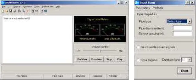
LeakfinderRT is a new system for locating leaks in municipal water distribution and transmission pipes using the cross-correlation method. This leak noise correlation system is fully realized in software for personal computers (PCs) running under Microsoft Windows XP, 2000, or 9x. The system utilizes the PC’s soundcard and other multimedia components to record and playback leak signals. It also uses the PC’s central processing unit (CPU) to perform the cross-correlation operation and associated signal conditioning. Modern PCs incorporate fast CPUs and high-resolution soundcards and hence offer several advantages over existing commercial hardware implementation of the cross-correlation method. Hardware components of the LeakfinderRT system are shown in Figure 1 and are composed of leak sensors, wireless signal transmission system, and a PC. The menu-driven user interface of the system’s software is shown in Figure 2. The software can be installed on either a notebook PC or a desktop one having a soundcard with a stereo line-in port.
The use of PCs eliminates the need for a major component of the usual hardware of leak noise correlators. Most potential users of LeakfinderRT already have PCs, which reduces the cost of the system. The use of Microsoft Windows makes the process of using the fully menu-driven system a simple and intuitive one as most potential users are already familiar with Windows. LeakfinderRT incorporates several new developments, most importantly an enhanced correlation function. For narrow-band leak noise, this new function dramatically improves the definition of correlation peaks. This is important for plastic pipes, multiple-leak situations, and in settings where leak sensors have to be closely spaced. Also, the enhanced correlation function is more effective than the traditional correlation function for small leaks and for situations of high background noise.
Accelerometers sense leak-induced vibration
Hydrophones (optional) sense leak-induced sound
Wireless transmitters broadcast leak noise sensed by leak sensors Wireless receiver picks up
broadcasted leak noise Computer records and
correlates leak noise
Figure 2 Main interface and input windows of LeakfinderRT
Correlation of Leak Noise
Locating leaks in water distribution and transmission pipes is a classical application of the cross-correlation method. Two things make this possible. First, the propagation velocity of leak sounds in water pipes is nearly constant over the dominant frequency range of leak sounds. Second, water-filled pipes transmit leak signals for long distances. Therefore, the shape of leak signals does not change significantly as they travel away from the leak, which is a pre-requisite for a successful correlation.
A typical field set-up of the correlation technique is shown in Figure 3. The correlation function of leak noise signals measured at the two points that bracket the location of a suspected leak provides information about the time delay (or lag) between the two signals. The time delay between the two leak signals is the result of one measurement point being closer to the leak location than the other. If the two measurement points are symmetrically positioned about the leak location, leak signals will arrive simultaneously at the two points and the time delay will be zero. On the other hand, if the leak location is exactly at the position of one of the two measurement points (or equivalently it is not between the two points), the time shift will be equal to the distance between the measurement points divided by the propagation velocity of leak noise in the pipe.
The correlation magnitude of two leak noise signals is the summation of their product as a function of time shift. In simple terms, the correlation value at time shift τ is computed by first shifting one of the signals by τ relative to the other signal. Then the two signals are multiplied, point-by-point, and the products are summed. The correlation function will display a peak at the time shift, which corresponds to the actual delay between the two leak noise signals (this is the time at which the two signals overlap).
LeakfinderRT determines the time delay τmax corresponding to the peak of the
cross-correlation automatically. In reference to Figure 3, the time delay between the two leak noise signals is related to the location of the leak relative to measurement points by
c L L2 1 max − = τ
where L1 and L2 are the positions of the leak relative to sensors 1 and 2, respectively, and c is
the propagation velocity of the leak sound in the pipe. By substituting L2 = D – L1 in the
2 max 1 τ ⋅ − = D c L
where D is the distance between the sensors, either measured on site or read off system maps. The propagation velocity can be specified if it was measured onsite or it can be calculated theoretically by LeakfinderRT based on input for pipe material type and diameter.
In the presence of material and geometric discontinuities, e.g., joints of dissimilar pipes and sharp bends, the cross-correlation method may lead to false results. This is because leak signals are partially or completely reflected at the discontinuities. Reflected leak signals create spurious peaks in the cross-correlation function which can be mistakenly interpreted as real leaks. For example, the presence of an out-of-bracket reflector at distance LR from the closest
leak sensor may create a spurious cross-correlation peak at distance LR from the actual
position of the leak. An in-bracket reflector may create a spurious peak at the location of the reflector itself.
If there is more than one leak between sensor positions 1 and 2, the cross-correlation function will have a peak corresponding to each leak. However, if the leaks are closely spaced, the peaks will overlap and in turn distort the corresponding time delay. The peak width depends on the bandwidth of the leak noise; the wider the frequency bandwidth of leak signals, the narrower the cross-correlation peak. The frequency bandwidth of leaks in metal pipes is much wider than that of leaks in plastic ones. For metal pipes, it may be possible to resolve leaks that are 6 m apart; for plastic pipes it may not be possible to accurately resolve leaks that are less than 20 m apart.
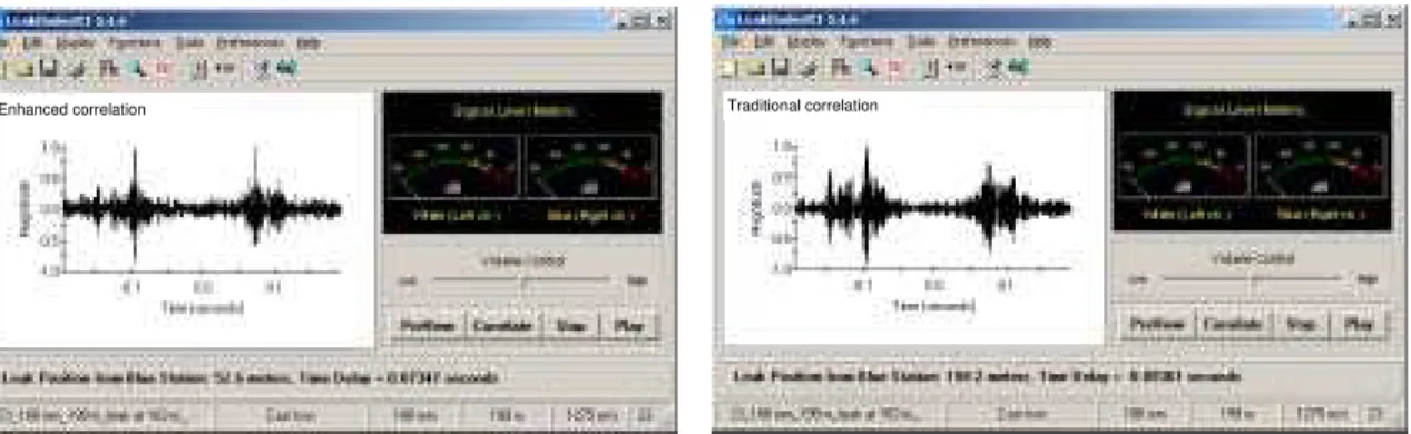
LeakfinderRT uses an enhanced cross-correlation function which is calculated indirectly in the frequency domain using the inverse Fourier transform of the cross-spectral density function instead of the usual shift-and-multiply method in the time domain. For narrow-band leak signals, the enhanced correlation function provides improved resolution, i.e., better definition of peaks, in comparison with the traditional correlation function. This is helpful for plastic pipes, for situations of multiple leaks, and for settings where leak sensors are closely spaced. Also, the enhanced correlation function is more effective than the traditional function for small leaks or for situations of high background noise. Performance examples are presented further on to demonstrate these advantages for leaks in both plastic and metal pipes. The enhanced correlation function does not require the usual filtering of leak signals for removing interfering noise. This is a major advantage over the traditional correlation method because it eliminates the uncertainty involved in selecting filter cutoff frequencies.
Measurement of Leak Noise
Leak signals are measured using either vibration sensors or hydrophones. Accelerometers, which sense the acceleration of vibration induced by leak signals in the pipe wall or fittings, are normally used to measure leak signals in metal pipes. These sensors are attached to the pipe directly, if accessible; if not they can be attached to fire hydrants or underground valves. A magnetic base is fitted to the base of these sensors and hence they are easy to install on metallic surfaces. Accelerometers can also be used to measure leaks in plastic pipes but they are only effective for large leaks.
LeakfinderRT’s special low-frequency vibration sensors and hydrophones are significantly more effective than accelerometers. Hydrophones, which are underwater microphones that sense pressure perturbations (sound) induced by leak noise in the water core of the pipe, are installed at fire hydrants or air release valves by using special fittings. Installation of
Figure 3 Schematic illustration of the field setup of the cross-correlation technique for locating a suspected leak
hydrophones is more difficult and more time-consuming than that of accelerometers. However, they are more effective for measuring leak signals in difficult situations, e.g., in the case of weak signals from small leaks, at sites with high background vibration levels, and for large sensor-to-sensor distances. Also, hydrophones are more effective than accelerometers for low-frequency leak signals, which are found in plastic pipes and large-diameter ones (plastic or otherwise).
LeakfinderRT’s low-frequency vibration sensors are almost as effective as hydrophones for plastic pipes but they are much easier to install because they are attached to the pipe directly or to fully pressurized fire hydrants. For example, the smallest service connection leaks in a 152-mm PVC pipe, under 60 psi pressure, correlated over a distance of about 100 m that could be successfully located using low-frequency vibration sensors and hydrophones were 1.7 and 0.85 liters per minute (see Figures 4c and 4d), respectively. In comparison, the smallest leak that could be located with accelerometers under the same conditions was 20 liters per minute. A joint leak having a flow rate of 6 and 3.25 liters per minute in the same pipe, under 60 and 20 psi pressure, respectively, was also successfully located with both low- frequency vibration sensors and hydrophones about 100 m apart (see Figure 4a and 4b for correlation of vibration sensor-measured signals).
The shorter the sensor-to-sensor spacing the better. For plastic pipes, it may not be possible to locate leaks with spacing greater than 100 m with the low-frequency vibration sensors. For larger distances, the use of hydrophones is recommended. For metal pipes, sensor-to-sensor spacing can be as large as 500 m but a maximum spacing of 200 m is recommended.
Signals from leak sensors are transmitted wirelessly to the PC for processing by using radio frequency transmitters and receivers. The received signals are fed into the line-in port of the PC’s soundcard. LeakfinderRT’s wireless system transmits leak signals almost without distortion – for input levels at 200 micro volts, its flat frequency response starts to roll down and its phase starts to become nonlinear at about 10 Hz (-6 dB point is at 5 Hz). It also has a low noise floor; e.g., it is capable of transmitting leak signals as small as 0.5 micro volts.
Receiver Computer
Suspected Leak Pipe
Recording of Leak Noise
LeakfinderRT records leak sounds by using the soundcard of the PC. The soundcard is set automatically to stereo mode (i.e., dual channel input) and to 16-bit resolution for maximum accuracy. Signals from the wireless receiver’s line-out should be fed into the STEREO line-in port of the PC’s soundcard. The signals are then converted by the soundcard to digital samples at the rate of 11025 Hz (i.e., samples per second).
By default, leak sounds are recorded and correlated by LeakfinderRT for an indefinite duration. The cross-correlation results are displayed on screen and continuously updated in real time while leak signals are being recorded. This default mode is convenient for situations in which leak signals are weak and may need to be correlated for a long time to average out interfering noise. The correlation operation can be terminated at any time. Normally, in the presence of a leak, a duration of 30 to 60 seconds is sufficient to obtain a definite peak in the cross-correlation function, but a much longer duration may be needed for small leaks and / or noisy environments. Recorded signals can be saved to the PC’s hard drive. Leak signals are saved in standard PCM sound file format and can be later converted to ASCII format for exporting to other applications, if needed.
Before recording and correlating leak signals, the recording volume must be adjusted to utilise as much as possible of the soundcard’s voltage range, without overloading it. This helps to achieve a high signal-to-noise ratio. LeakfinderRT has a signal preview function to help check the level or volume of leak sounds (signals are not saved to disk during previewing). The level of leak noise signals is displayed via two level meters (see Figure 2). The recording volume must be adjusted so that the signal level does not fall in the red range of the level meters, just like recording music on a home stereo audio system.
At the start of the correlation operation the user is prompted to input only the following three parameters:
– pipe type, – pipe diameter, and – sensor-to-sensor spacing.
The software sets all other correlation and signal processing parameters automatically. The user can opt to input pipe wall thickness (in addition to the diameter), propagation velocity if known (instead of diameter), or none of the preceding (pipe type only). For multi-type pipes, properties can be input for different pipe sections.
Playback of Leak Noise
A file containing leak sounds saved by LeakfinderRT on the PC’s hard disk can be played back. The software does not alter the raw data in a saved leak sounds file and hence the data can be played back and re-correlated repeatedly. Also, the complete time history of saved leak signals can be displayed graphically on screen and printed.
The speed at which leak signals are played back can be increased arbitrarily. This is helpful when playing back noise signals of leaks in plastic and large-diameter pipes. In these pipes, leak signals are dominated by low-frequency components, mainly in the infrasound range, and thus cannot be heard by an unaided human ear. Speeding up the playback of low-frequency signals shifts their frequency components to a higher range at which the sensitivity of human hearing is high enough to discern the leak sound.
Propagation Velocity of Leak Noise
LeakfinderRT calculates the propagation velocity of leak noise using a theoretical formula based on input for pipe type, diameter and wall thickness. If the wall thickness is not input, the software estimates it based on pipe type and diameter. If the diameter is also unknown, the propagation velocity is calculated as the average of velocities corresponding to several diameters. It should be emphasised that velocity values calculated theoretically are approximate and are provided only for preliminary leak location. Leak positions based on these approximate values can be inaccurate, especially for non-metallic pipes. For improved accuracy, it is recommended that the propagation velocity be measured onsite using a known in-bracket or out-of-bracket simulated leak, for example, by drawing water at a fire hydrant or service connection. An in-bracket leak produces signals that are more similar than those produced by an out-of-bracket one and is preferred. LeakfinderRT has a built-in velocity calculator that facilitates this operation.
Output
Frequency spectra of leak signals, coherence, and correlation functions are output graphically by LeakfinderRT. Frequency spectra provide information about the frequency content of leak signals. The coherence function provides a measure of the relationship between recorded leak signals, i.e., whether they were induced by the same source or not. The closer the coherence function is to 1, the more related the signals. Small coherence values indicate high noise-to-signal ratio (e.g., in the case of leaks creating weak noise). The correlation function provides information about the time delay between leak noise signals, which in turn is used to calculate the leak location.
Any of the above functions can be displayed individually in the main interface window where they are updated in real time while the recording and correlation of leak signals is in progress. They can also be displayed together in a separate window at the end of the recording and correlation process. The graphs have a zoom button and a live cursor. For the correlation function, the software re-calculates the leak position corresponding to any time shift of any peak or point in the correlation function. The output also includes the time shift corresponding to the peak of the correlation function, and the leak position. The output can be sent to a Windows default printer, copied to a Windows clipboard for pasting in other applications, or exported to an Excel spreadsheet.
Performance Examples
LeakfinderRT was verified extensively using pure tones, random signals, and field tests on in-service water distribution pipes. Performance examples of LeakfinderRT’s enhanced correlation method versus the traditional method are shown in Figures 4 and 5 for plastic and metal pipes, respectively. These results demonstrate the following advantages and capabilities of the LeakfinderRT system utilizing the enhanced correlation method:
– Figure 4a: Improved peak definition for narrow-band leak noise in PVC pipes. – Figure 4b: Superior sensitivity for detecting small leaks in PVC pipes under a
very low pressure of 20 psi (~15 m).
– Figures 4c and 4d: Smallest detectable PVC pipe leaks using LeakfinderRT’s low frequency vibration sensors (1.7 liters per minute) and using hydrophones (0.85 liters per minute).
– Figure 5a: Improved peak definition for resolving multiple leaks. – Figure 5b and 5c: Effectiveness for locating small leaks in metal pipes. – Figure 5c and 5d: Effectiveness for situations of high background noise.
Con clu sion s
A new system for locating pipe leaks based on the cross-correlation method is introduced. The system incorporates several new developments, most importantly an enhanced correlation method. For narrow-band leak noise, this new function dramatically improves the definition of correlation peaks. This is important for plastic pipes, multiple-leak situations, and in settings where leak sensors have to be closely spaced. Also, the enhanced correlation function is more effective than the traditional one for small leaks or for situations of high background noise. The enhanced function does not require the usual filtering of leak signals for removing interfering noise. This is a major advantage because it eliminates the uncertainty involved in selecting filter cutoff frequencies.
Another major advantage of the new system is the use of low-frequency vibration sensors instead of the inconvenient use of hydrophones to locate leaks in traditionally difficult plastic pipes. The effectiveness of these low-frequency vibration sensors is demonstrated for locating small service leaks and joint leaks in PVC pipes, even when under low pipe pressures.
In addition to the effectiveness of the new system, it is very easy to use and low in cost. This is a result of using personal computers as a platform to both record and analyse leak signals, which eliminates a major component of the usual hardware of leak noise correlators. Consequently, the new system has promising potential for all water utilities, including small and medium-sized ones and utilities in developing countries.
Re f e r e n ce s
AWWA (1999). Water Audits and Leak Detection. Manual of Water Supply Practices M36, American Water Works Association, Denver, CO.
AWWA (1987). Leaks in Water Distribution Systems – A Technical/Economic Overview. American Water Works Association, Denver, CO.
Cheong, L.C. (1991). Unaccounted-for Water and the Economics of Leak Detection. Proc. International Water Supply Congress and Exhibition, Copenhagen, published in Water Supply, Volume 9, pp. IR 1-1 to 1-6. Colombo, A.F., and Karney, B.W. (2002). Energy and Costs of Leaky Pipes: Toward a Comprehensive Picture.
Journal of Water Resources Planning and Management, Volume 128, No. 6, pp. 441-450. EPA (2003). EPA Will Help Consumers Locate and Purchase Water-Efficient Products. Newsroom,
Environmental Protection Agency, U.S.A., posted at “www.epa.gov/newsroom/headline_090503.htm”. Hunaidi, O., Chu, W., Wang., A., and Guan, W. (2000). Detecting Leaks in Plastic Water Distribution Pipes.
Journal AWWA, Volume 92, No. 2, pp. 82-94, posted at: “irc.nrc.gc.ca/fulltext/nrcc43058.pdf”.
Hunaidi, O., and Chu, W. (1999). Acoustical Characteristics of Leak Signals in Plastic Water Distribution Pipes. Applied Acoustics, Volume 53, pp. 235-254, posted at: “irc.nrc.gc.ca/fulltext/nrcc42673.pdf”.
IWA (2000). Manual of Best Practice: Performance Indicators for Water Supply Services. International Water Association, London, U.K.
James, K., Godlove, C.E., and Campbel, S.L. (2002). Watergy: Taking Advantage of Untapped Energy and Water Efficiency Opportunities in Municipal Water Systems. Alliance to Save Energy, Washington, DC, posted at: “www.watergy.org”.
Lambert, A. (2001). What Do We Know About Pressure / Leakage Relationships in Distribution Systems? Proc. IWA Specialised Conference: System Approach to Leakage Control and Water Distribution Systems Management, Brno, Czech Republic, 16-18 May 2001, pp. 89-96.
Tai, Y. (2004). China Faces Serious Water Shortages. The Washington Times, 23 March 2004, posted at “www.washtimes.com/upi-breaking/20040322-121420-7382r.htm”.
TWGWW (1980). Leakage Control Policy and Practice. Report No. 26 by Technical Working Group on Waste of Water, National Water Council, Department of the Environment, U.K.
UKWIR (1999). Manual of DMA Practice. Published by UK Water Industry Research Limited, London. U.K. van der Klejj, F.C., and Stephenson, M.J. (2002). Acoustic Logging – The Bristol Water Experience. Proc. IWA
Specialised Conference: Leakage Management – A Practical Approach, International Water Association, 20-22 November 2002, Lemesos, Cyprus, posted at “www.leakage2002.com”.
WLCC (2003). Applying Worldwide BMPs in Water Loss Control (Report by AWWA Water Loss Control Committee). Journal AWWA, Volume 95, No. 8, pp. 65-79.
(a) 6 liters / minute joint leak in 152-mm PVC pipe (sensor type: low-frequency vibration sensor, sensor spacing: 102.6 m, pipe pressure: 70 psi, 02.010703)
(b) 3.25 liters / minute joint leak in 6-inch PVC pipe (sensor type: low-frequency vibration sensor, sensor spacing: 102.6 m, pipe pressure: 20 psi, 03.010703)
(c) 1.7 liters / minute service connection leak in 152-mm PVC pipe (sensor type: low-frequency vibration sensor, sensor spacing: 102.6 m, pipe pressure: 60 psi, 06.200703)
(d) 0.85 l liters minute service connection leak in 152-mm PVC pipe (sensor type: hydrophone, sensor spacing: 102.6 m, pipe pressure: 60 psi, 11.270603)
Figure 4 Performance of LeakfinderRT’s enhanced correlation method versus traditional method for PVC pipe leaks
Enhanced correlation Traditional correlation
Traditional correlation Traditional correlation Enhanced correlation Enhanced correlation Traditional correlation Enhanced correlation
(a) Multiple leaks in 100-year old, 100-mm cast iron pipe (sensor type: accelerometer, sensor spacing: 199 m, pipe pressure: unknown, 01.040301)
(b) 1 liter / minute fire hydrant leak in152-mm ductile iron pipe (sensor type: accelerometer, sensor spacing: 128.5 m, pipe pressure: 60 psi, 14.200703)
(c) 2 liters / minute fire hydrant leak in152-mm ductile iron pipe (sensor type: accelerometer, sensor spacing: 134.5 m, pipe pressure: 60 psi, 17.090303)
(d) 25 liters / minute fire hydrant leak in152-mm ductile iron pipe (sensor type: accelerometer, sensor spacing: 128.5 m, pipe pressure: 60 psi, 15.200703)
Figure 5 Performance of LeakfinderRT’s enhanced correlation method versus traditional method for metal pipe leaks
Traditional correlation Traditional correlation Traditional correlation Enhanced correlation Enhanced correlation Enhanced correlation Traditional correlation Enhanced correlation