Publisher’s version / Version de l'éditeur:
Fire Technology, 42, January 1, pp. 5-26, 2006-01-01
READ THESE TERMS AND CONDITIONS CAREFULLY BEFORE USING THIS WEBSITE. https://nrc-publications.canada.ca/eng/copyright
Vous avez des questions? Nous pouvons vous aider. Pour communiquer directement avec un auteur, consultez la
première page de la revue dans laquelle son article a été publié afin de trouver ses coordonnées. Si vous n’arrivez pas à les repérer, communiquez avec nous à PublicationsArchive-ArchivesPublications@nrc-cnrc.gc.ca.
Questions? Contact the NRC Publications Archive team at
PublicationsArchive-ArchivesPublications@nrc-cnrc.gc.ca. If you wish to email the authors directly, please see the first page of the publication for their contact information.
NRC Publications Archive
Archives des publications du CNRC
This publication could be one of several versions: author’s original, accepted manuscript or the publisher’s version. / La version de cette publication peut être l’une des suivantes : la version prépublication de l’auteur, la version acceptée du manuscrit ou la version de l’éditeur.
For the publisher’s version, please access the DOI link below./ Pour consulter la version de l’éditeur, utilisez le lien DOI ci-dessous.
https://doi.org/10.1007/s10694-005-3730-y
Access and use of this website and the material on it are subject to the Terms and Conditions set forth at
Factors influencing fire resistance of load-bearing steel stud walls
Kodur, V. K. R.; Sultan, M. A.
https://publications-cnrc.canada.ca/fra/droits
L’accès à ce site Web et l’utilisation de son contenu sont assujettis aux conditions présentées dans le site LISEZ CES CONDITIONS ATTENTIVEMENT AVANT D’UTILISER CE SITE WEB.
NRC Publications Record / Notice d'Archives des publications de CNRC: https://nrc-publications.canada.ca/eng/view/object/?id=0cfb8696-d970-4b2d-af26-ed5c0606b0de https://publications-cnrc.canada.ca/fra/voir/objet/?id=0cfb8696-d970-4b2d-af26-ed5c0606b0de
http://irc.nrc-cnrc.gc.ca
Fa c t ors influe nc ing fire re sist a nc e of
loa d-be a ring st e e l st ud w a lls
N R C C - 4 6 2 9 0
K o d u r , V . K . R . ; S u l t a n , M . A .
A version of this document is published in / Une version de ce
document se trouve dans: Fire Technology, v. 42, no. 1, Jan. 2006,
pp. 5-26.
doi:10.1007/s10694-005-3730-y
Factors Influencing Fire Resistance of Load-bearing Steel Stud Walls
by
V. K. R. Kodur and M. A. Sultan
Fire Research Program, Institute for Research in Construction,
National Research Council, Ottawa, Canada.
ABSTRACT
This paper presents the effect of various factors on the fire resistance of load-bearing, gypsum board protected, steel stud wall assemblies. A detailed experimental study was conducted to evaluate the fire resistance of 14 full-scale steel stud wall assemblies. Both single row and double row steel stud configurations with installation of gypsum board on each of the exposed and unexposed sides, and with and without insulation in the cavity, were considered in the experimental program. The insulation used were glass, rock and dry blown cellulose fibers. Data from the experimental program are used to determine the effects of stud-spacing, shear membrane, load intensity, resilient channel installation, insulation type and gauge thickness of studs on the fire resistance of gypsum board-protected, steel stud wall assemblies. Results from the studies show that the insulation type and number of gypsum board layers have significant influence on the fire resistance of steel stud wall assemblies.
Keywords: fire resistance, load-bearing wall, cold-formed steel, steel stud wall,
gypsum board
INTRODUCTION
In recent years, lightweight steel framing (LSF) has found increased application in residential and commercial construction. Load-bearing LSF walls are used as party walls in townhouses, and as party or corridor walls in multi-unit low-rise steel frame buildings. In such instances, these walls have to meet certain fire resistance requirements. However, there is no information provided in the NBCC [1], and only limited information is in literature [2,3], on the performance of load-bearing LSF walls in fire.
To generate data on the fire resistance of various types of wall assemblies, a major collaborative research project, incorporating 9 industry partners, was initiated by the National Research Council of Canada (NRCC). A total of 14 full-scale fire resistance experiments were carried out to study the effects of stud arrangement, shear bracing or membrane, load intensity, resilient channel installations, insulation and steel thickness of studs on the fire resistance of gypsum board protected, steel stud wall assemblies. The fire resistance tests were carried out in accordance with CAN/ULC S101 [4].
The wall systems tested were representative of wall assemblies currently used in North America. Steel stud walls were provided with either cross-bracing or a shear membrane to enhance shear resistance to lateral loads. Resilient channels and various types of cavity insulation, that are often used in wall designs to improve their sound transmission classification (STC) ratings, were considered in the experimental program to determine their effect on fire resistance. The purpose of this study was to establish the
influence of various parameters on the fire resistance performance for generic load-bearing steel stud walls with various configurations. Also, extensive temperature and deformation measurements were also undertaken during the experimental studies in order to generate data useful for analytical studies and for the development of numerical models. A summary of the results from these fire resistance experiments, including the effect of various parameters on the fire resistance of steel stud wall assemblies, are presented in this paper.
EXPERIMENTAL STUDIES
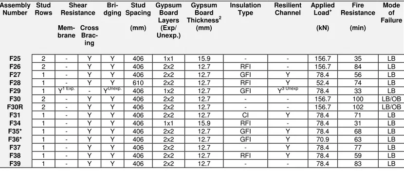
The experimental program consisted of fire tests on 14 full-scale steel stud wall assemblies and represented walls commonly used in North America. Thirteen of the wall assemblies were provided with steel cross-bracing to enhance lateral resistance, while the fourteenth wall assembly was provided with an OSB shear membrane. All assemblies were protected with Type X gypsum board on both fire-exposed and unexposed sides. The assemblies were designated as F25, F26, F27, F28, F29, F30, F30R, F31, F34, F35, F36, F37, F38 and F39. The various details for each of the walls such as depths, number of layers of gypsum board, resilient channels and insulation type are given in Table 1.
Wall Assemblies
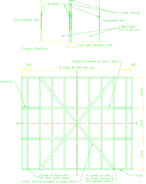
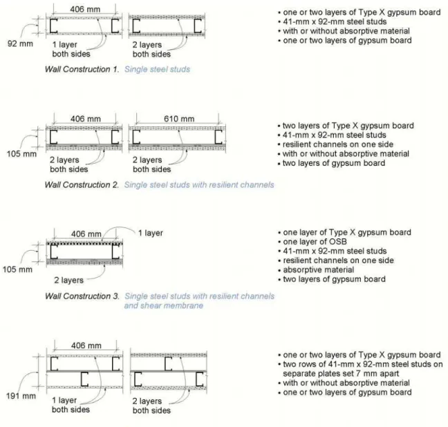
The steel stud wall assemblies were 3048 mm high by 3658 mm wide with various depths depending on number of rows of studs, layers of gypsum board and the presence of resilient channels. Each assembly consisted of either a single or double row of galvanized cold-formed steel studs, protected with one or two layers of Type X gypsum board on each side. The specific dimensions of a typical steel stud party wall assembly tested are given in Figure 1. The cross-sectional sketches of wall assemblies are shown in Figure 2. Table 1 provides a summary of the variable parameters of the wall specimens.
The wall frames were constructed using cold-formed steel studs, meeting the requirements of CSA-S136 [5]. Wall Assemblies F35 and F36 were fabricated from "MSG 20 light" (Manufacturers Standard Gauge) steel studs with a nominal bare steel thickness of 0.84 mm, while the remaining walls were fabricated from “MSG 20” studs with a nominal bare steel thickness of 0.912 mm. All studs had a C-shaped cross-section, 92 mm deep by 41 mm wide, with 12.7 mm stiffening lips. The studs were fabricated from galvanized steel sheets having a minimum specified yield strength of 228 MPa [5] and ultimate tensile strength of 310 MPa. Each stud had 4 web perforations, 38 mm wide, spaced 610 mm o.c. along the stud length.
All wall assemblies, except F29, had diagonal cross-bracing to enhance shear resistance to lateral loads designed in accordance with CSA-S136 [5]. For Assembly F29, oriented strand board (OSB) structural panels were used as shear membrane as an alternative to cross-bracing. The OSB panels were 12.7 mm thick Weyerhaeuser Sturdy-Wood Structural Panels with a mass per unit area of 8.08 kg/m².
The gypsum board used in all tests had the Firecode C designation and met the requirements of CAN/CSA-A82.27 [6] and ASTM C36 [7] for Type X gypsum board. Type X gypsum boards are generic fire resistive materials with fire resistance properties clearly defined in ASTM C 1396, Standard Specification for Gypsum Board, however, type C gypsum boards are proprietary with fire resistance properties intended for use is specific fire resistive assemblies. Type X gypsum boards are interchangeable among manufacturers, however, type C gypsum boards are not. Type C is slightly more fire resistive than type X
and can be substituted for type X wherever type X is specified, however, type X cannot be arbitrarily substituted for type C. The gypsum board used was supplied in 3048 mm long by 1219 mm wide sheets. The thicknesses of Type X gypsum board used in the assemblies were 12.7 mm and 15.9 mm.
Three different types of insulation, all meeting the requirements of CAN/CSA-A101,[8] were used in this test series, namely, glass fibre (with bulk density of 10 kg/m3), rock fibre (33 kg/m3) and dry blown cellulose (47 kg/m3). Glass fibre batts, 92 mm thick, 1219 mm long and 406 mm wide, and rock fibre batts, 89 mm thick, 616 mm wide and 1256 mm long were placed between the studs of wall assembly. The cellulose insulation was dry-blown into the wall cavity of in Assembly F31.
The resilient channels used in the wall assemblies were 14 mm deep and 58 mm wide, and were fabricated from 0.46 mm thick galvanized steel sheets. The channels had a 30 mm wide web, designed to support the gypsum board connections, and a 15 mm wide flattened flange lip, connected to the steel studs by 19 mm long self-drilling wafer head screws.
Construction Details
The full-scale assemblies were constructed in accordance with CSA-S136 [5] and CAN/CSA-A82.31 [6]. Full details on fabrication of these wall assemblies, with detailed drawings, are given in Ref. [9].
Steel Stud Framing: The wall assemblies were constructed in the wall furnace test frame at the NRCC. Wall Assemblies F27-F29, F31 and F34-F39 had a single row of studs, while Assemblies F25, F26, F30 and F30R had a double row of studs. In all wall assemblies, except for F28, steel studs were spaced at 406 mm o.c. In Assembly F28 the spacing was 610 mm.
In double row steel stud wall assemblies, to accommodate the dimensions of the test frame and the stagger of the two parallel stud rows, a reduced stud spacing of 386 mm was used on the east and west ends of the stud row on the unexposed side. Also, a reduced spacing of 183 mm was used on the ends of the stud row on the fire exposed side. Similarly, in all single row stud walls, except Assembly F28, a reduced stud spacing of 386 mm was used on the ends. In Assembly F28 the reduced spacing was 590 mm.
The lateral support to the compression flange of steel studs was provided by means of 2 rows of bridging, and solid blocking in 4 locations. The bridging and solid blocking was designed in accordance with CSA-S136 [5]. Galvanized steel straps were used for bridging, while the blocking was fabricated from steel stud sections. The straps were 39 mm wide (fastened with #8 self-drilling screws to each stud) and the blocking was 0.912 mm thick track (copped, fastened with 4 #8 self-drilling screws). All the tracks and cross-bracing material were of “MSG 20” gauge.
Galvanized steel straps were used for cross-bracing and the straps were 39 mm wide (fastened with #8 self drilling screws to each stud). The gusset plate was 101x101x0.912 mm and was attached to the frame with 4 #8 self drilling screws each way. The strap was attached to the gusset with the same number of screws.
Details of stud arrangement, as well as cross-bracing, bridging and blocking, are provided in Reference [9].
Gypsum Board Application: Wall Assemblies, except for F25, F29 and F34, were protected with 2 layers of 12.7 mm thick Type X gypsum board on both fire exposed and unexposed sides. Wall Assemblies F25 and F34 were protected with a single layer Type X gypsum board, 15.9 mm thick on both fire exposed and unexposed sides. Assembly F29 had 2 layers of 12.7 mm thick Type X gypsum board on the unexposed side, while on the fire exposed side, it had a face layer of 12.7 mm thick Type X gypsum board and a base layer of 12.7 mm thick OSB.
In all single row steel stud wall assemblies, with a double layer of gypsum board, the installation of the gypsum board was conducted in accordance with CAN/CSA-A82.31 [10]. The base layer was attached to the steel studs (or to the resilient channels in assemblies with resilient channels) with drywall screws, spaced at 305 mm o.c. along the edges of the gypsum board and 610 mm in the field of the board. The face layers were attached to base layers of the gypsum board and to the steel studs (or to the resilient channels in assemblies with resilient channels) with drywall screws, spaced at 305 mm o.c. along the edges of the gypsum board, as well as in the field of the board.
In Wall Assemblies F25 and F34, with a single layer of gypsum board, the gypsum board was attached to the steel studs with drywall screws, spaced at 610 mm o.c. along the edges of the gypsum board as well as in the field of the board.
In double row steel stud walls, with a double layer of gypsum board, the base layer was attached to the steel studs with drywall screws, spaced at 610 mm o.c. along the edges of the gypsum board and in the field of the board. The face layers were attached to the base layers of the gypsum board and to the steel studs with drywall screws, and were spaced at 406 mm o.c. along the edge of the gypsum board, as well as in the field of the board.
In wall assemblies without resilient channels, the gypsum board on both the fire- exposed and the unexposed side were applied vertically and attached to the steel studs. In walls with resilient channels (F27, F28, F31, F35-F38), on the unexposed side the two layers of gypsum board were applied vertically, with regularly staggered joints, and attached directly to the steel studs as above. On the fire-exposed side, the gypsum boards were oriented horizontally and attached to the resilient channels. The base layer boards were attached by drywall screws spaced 305 mm o.c. along the edges, and 610 mm o.c. along intermediate resilient channels. The edge joints of these boards were oriented parallel to, and located over the resilient channels. The face layer boards were attached by drywall screws spaced 305 mm along the edges and intermediate resilient channels. The edge joints of the face layer boards were oriented parallel to, and located over, resilient channels and offset 406 mm from the base layer edge joints. There was a 1219 mm long unsupported vertical joint in the base layer, and a similar 812 mm long vertical joint in the face layer.
In Wall Assembly F29 (assembly with resilient channels), the unexposed side had two gypsum board layers (installed as per above) on resilient channels and the fire-exposed side had one gypsum board layer as a face layer and the shear wall panel (OSB) as the
base layer. The shear panels were attached to the steel studs with 32 mm bugle head #10 screws spaced at 152 mm o.c. at the panel edges and 305 mm o.c. in the field of the panels. The face layer gypsum board on the fire-exposed side was attached to the OSB shear wall panels and the studs with drywall screws spaced at 305 mm o.c. along the edges and in the field of the gypsum board.
The detailed layout and screw arrangement of the base and face layers of gypsum board (or shear panel for Wall Assembly F29) on the fire-exposed and unexposed side for various assemblies are given in Ref. [9].
All drywall screw heads on both the fire-exposed and unexposed sides were covered with two applications of joint compound. Also, gypsum board joints on the face layer of both sides were taped and covered with two applications of joint compound.
Insulation: Nine of the wall assemblies had insulation. Wall Assemblies F27, F29, F35 and F36 were filled with glass fiber insulation batts, while Assemblies F26, F28, F34 and F38 were filled with rock fiber insulation batts. Assembly F31 was filled with loose fiber cellulose insulation.
Glass fiber batts (92 mm thick, 406 mm wide and 1219 mm long and) and rock fiber batts (89 mm thick, 414 mm (or 617 mm for studs spaced at 606 mm) wide and 1228 mm long) were placed between the studs of the wall assembly. The cellulose insulation was dry-blown into the cavity of Wall Assembly F31. For the purpose of cellulose insulation placement, the cavity was formed, after the installation of the gypsum board on the unexposed side of the wall, by the attachment of a polypropylene mesh to the steel studs on the fire-exposed side of the steel frame (the mesh formed a vertical plane between the studs and resilient channels).
Resilient Channel Installation: Wall assemblies F27, F28, F31, and F35-38 had resilient channels on the fire-exposed side, while Assembly F29 had resilient channels on the unexposed side. Nine rows of resilient channels, spaced 406 mm o.c. horizontally, were attached perpendicular to the studs on the fire-exposed side (unexposed side in the case of Assembly F29) of the frame.
The gypsum boards on the fire-exposed side were oriented horizontally and attached to the resilient channels, as explained above, with two horizontal joints, 3658 mm long, and a vertical unsupported joint, 1219 mm long. Full details on the resilient channel layout and their application to the wall assemblies is given in Ref. [9].
Further details on the construction of the wall assemblies are given in References [9].
Instrumentation
In accordance with CAN/ULC-S101-M89 [4], thermocouples were installed on the unexposed surface of the assembly under insulated pads at 9 locations. Type K (20 gauge) chromel-alumel thermocouples, with a thickness of 0.91 mm, were used for measuring temperatures at these locations.
In addition, to generate experimental data for analytical studies, numerous locations within the wall specimens were also instrumented with thermocouples. In each assembly, these were arranged in 2 groups, symmetric with a horizontal plane at the mid-height of the wall, at 2 elevation levels: 762 mm from the bottom of the wall (25% wall height level) and 2286 mm from the bottom of the wall (75% height level). Most of the thermocouples were distributed within the central part of the wall specimens, about 2 m long, at the various interfaces and generalized locations.
Inside the cavities, the thermocouples were attached to 6 wire hangers installed midway between the studs and at mid-depth of the studs at distances of 1/4 and 3/4 of the height of the wall. By providing tension to the hanger wire, the thermocouples were positioned flush with the surface of the gypsum board layers. About 75-90 thermocouples were installed at various locations within the wall assembly.
A number of small holes, 12.7 mm in diameter, were drilled through the steel stud tracks at the bottom to allow the thermocouple wiring to exit the assembly.
Thermocouples located on the stud/base layer interfaces were secured in position by self-drilling wafer head screws and those located between the base and face layers were taped into position.
The out-of-plane horizontal deflection was measured by 9 deflection gauges connected by wires to the unexposed surface at various locations. These deflections were recorded using the electro-mechanical method described in Reference 11.
Details on thermocouple locations and deflection gauges for wall assemblies is documented in Ref. [9].
Test Conditions and Procedures
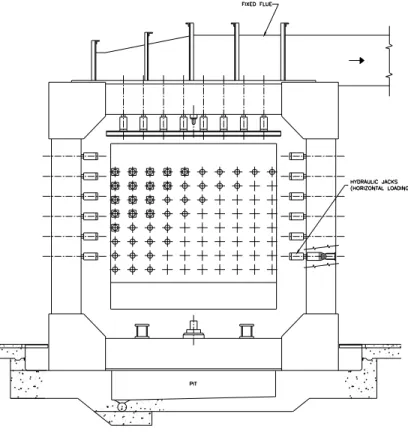
The tests were carried out by exposing the assemblies to heat in a propane-fired vertical furnace as shown in Figure 3. Details of the vertical furnace are given in Reference 12. Gaps between the test frame and the assembly on the vertical edges were sealed with ceramic fiber material. The furnace temperature was measured by 9 (20 gauge) shielded thermocouples in accordance with CAN/ULC-S101 [4].
The loading device consisted of 8 hydraulic jacks connected to a loading beam, which transferred the load to the specimen. The components of the loading device are a strong steel frame, in which the wall assembly is placed, and 8 hydraulic jacks fitted at the top to simulate vertical structural loads [12].
The load calculations for assemblies were carried out based on the material characteristics of the wall. The applied loading on the wall assemblies used in this study is presented in Table 1. The assembly was loaded with the hydraulic pressure computed based on the loads given in Table 1. The applied load on all wall assemblies, except F35, represents 90.5% of a full specified load. The load intensity on Assemblies F35 represent 100% of a full specified load. The full specified load represents the maximum design load on the assembly at room temperature.
The load was applied in increments and was maintained for 45 min before fire exposure. After exposure to fire, this load was maintained throughout the duration of the test. In double row steel stud walls the load was applied through a single plate over the two rows of steel studs to distribute the load.
The ambient temperature at the start of each test was approximately 22°C. During the test, the wall assembly was exposed to heating on the fire-exposed side in such a way that the average temperature in the furnace, located 150 mm away from the fire-exposed surface of the sample, followed as closely as possible the CAN/ULC-S101 [4] standard temperature-time curve. This is very similar to ASTM E-119 [13] standard temperature-time curve. The average temperature of the 9 thermocouples was used to control the furnace temperature.
The failure criteria for this test were derived from CAN/ULC-S101 [4] and ASTM-E119 [13]. In this case, the load-bearing wall assembly was defined to have failed if any of the following occurred:
• A single point thermocouple temperature reading under the insulated pad on the unexposed face rose 180°C above ambient temperature;
• The average temperature of the 9 thermocouple readings under the insulated pads on the unexposed face rose 140°C above the ambient temperature;
• There was passage of flame or gases hot enough to ignite cotton waste; • When a load-bearing wall assembly loses its ability to sustain the applied load.
The furnace and wall assembly temperatures, as well as the deflections, were recorded at 1-minute intervals using a data acquisition system. The gauge pressure of the loading system was also recorded at 1-minute intervals.
RESULTS AND DISCUSSION
The results of 14 full-scale fire resistance tests are summarized in Table 1 in which the failure times and mode of failure is given for each assembly. The fire resistance values (failure time) reported in Table 1, is the number of full minutes passed since the start of the furnace to the loss of the load-bearing function.
All wall assemblies failed structurally through local buckling. According to conditions of acceptance, [4, 13] the wall specimens failed by losing their ability to sustain the applied load. The unexposed surface temperature at the time of structural failure was below the temperature failure criteria for all assemblies.
In most tests, the structural failure proceeded in an abrupt manner, resulting in the overall out-of-plane buckling of the walls in the direction away from the furnace. The initiation of fall-off of the gypsum board on the fire-exposed side of the specimens was observed several minutes prior to structural failure. In most double layered assemblies, the base layer gypsum board on the fire-exposed side of the wall assemblies remained in place until the end of the test.
The deformed shapes of the steel studs were inspected after each test in
order to assess the structural failure modes. Structural failure resulted in overall
buckling towards the furnace for non-insulated walls and away from the furnace for
insulated walls. The dominant failure mode for studs in non-insulated walls was the
compressive failure of the cold flange near mid-height. In insulated walls, the interior
studs (except the end studs) had local buckling at about one-fifth the height from the
top (or bottom in some assemblies) while the whole assembly failed by overall
buckling at about one-third the height from the top of the wall. The studs typically
exhibited compressive failure (local buckling) of the hot flange at the location of the
first perforation (about 20% wall height level, counting from the bottom/top of the
wall). In some cases, studs exhibited similar compressive failure of the hot flange at
the second perforation (about 40% wall height level). This difference in the
observed structural behavior of steel studs in non-insulated and insulated walls can
be attributed to the difference in the heating regimes [3, 14]. Figure 4 shows the
typical wall assembly after the fire resistance test. Detailed temperature distribution
data at the various locations, including unexposed surfaces, and measured
deflection data for all wall assemblies can be found in Reference [9].
The average temperatures measured in the central part of the wall assemblies are illustrated in Figure 5 for Wall Assemblies F27, F28 and F31. Average hot flange temperatures just prior to structural failure were about 550ºC, 800ºC and 650ºC for specimens F27, F28 and F31, respectively. The unexposed side curves, presented in the figure, reflect the averages of temperatures recorded from thermocouples under pads. As expected, readings from thermocouples without pads on the unexposed side (not shown in the figure) produced lower average temperatures.
The plots of average lateral deflections measured in the central part of the wall assemblies are presented in Figure 6 for Wall Assemblies F27, F28 and F31. Positive horizontal deflections indicate movement towards the furnace. These reflect the thermal bowing [2, 3] and secondary deformations of the steel studs caused by the development of temperature gradients between the hot and cold flanges. In all three plots, the lateral deflection curves for the 25% wall height level are distinctive from the other two curves, showing an early reversal in the development of the positive lateral deflection. These reversals are consistent with the structural failure modes observed. In all tests, large negative (away from furnace) lateral deflections were recorded at all wall height levels after the structural failure (these are not shown on the plots in order to maintain an appropriate scale of the plots).
Vertical displacements recorded during tests F28 and F31 indicated upward movement of the loading beam, consistent with the thermal expansion of the studs, followed by a gradual downward movement during the last few minutes prior to structural failure.
FACTORS INFLUENCING FIRE RESISTANCE
Based on the results of the experimental studies, the effect of various factors on the fire resistance of steel stud shear wall assemblies can be summarised as follows:
Effect of Insulation Type
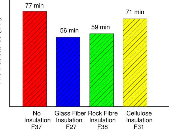
Results from fire resistance tests F27, F31, F37 and F38 can be used to determine the effect of insulation type on the fire resistance of load-bearing (single row) steel stud
walls (see Figure 7). These wall assemblies were of similar configuration except for the type of insulation. The uninsulated Wall Assembly, F37, provided the highest fire resistance of 77 minutes. The failure of the glass fiber insulated Wall Assembly (F27) occurred at 56 minutes, while the failure of the rock fiber (F38) and cellulose (F31) insulated wall assemblies occurred at 59 and 71 minutes, respectively. These results suggest that maximum fire resistance can be obtained in a steel stud wall assembly by not putting any insulation in the cavity. Further, the use of rock fiber insulation provides a slightly higher fire resistance compared to glass fiber insulation, but a lower fire resistance compared to cellulose fiber insulation.
The lower fire resistance in insulated assemblies is mainly because the gypsum board facing the fire is kept hotter when heat is blocked by the absorptive material, causing it to crack and fail more quickly than when the cavity is empty. This hastens the structural failure of the steel studs, which quickly lose load-carrying capacity at high temperatures. The higher fire resistance in the case of wall assemblies insulated with rock and cellulose fiber insulation can be attributed to rock and cellulose fiber insulation remaining in place slightly longer to protect the framing. In the case of glass fiber insulated wall assemblies, the glass fiber melts in about 2 to 3 minutes following the fall of gypsum board.
To verify the applicability of the above trend to the double row stud walls, fire resistance tests F30, F30R and F26, were conducted. Wall Assemblies F30 and F30R were uninsulated while Assembly F26 was insulated with rock fiber. In this case, the uninsulated Wall Assemblies (F30 and F30R) failed at 100 and 102 minutes, respectively, while the rock fiber (F26) insulated wall assemblies failed at 84 minutes (see Figure 7). These results again indicate that higher fire resistance can be obtained by not insulating the double row steel stud walls.
Effect of Resilient Channels
Tests F37 and F39 were conducted to investigate the effect of installation of resilient channels on the fire resistance of load-bearing steel stud walls. Both these assemblies were protected by 2 layers of gypsum board and had no insulation. Assembly F37 had resilient channels installed, at 406 mm o.c. spacing, on the fire-exposed side, while Assembly F39 did not have any resilient channels.
The failure of Wall Assembly F37 (with resilient channels) occurred at 77 minutes while in Assembly F39 (wall without resilient channels) the failure occurred at 83 minutes (see Figure 8). These results from the fire tests indicated that, for assembly with the resilient channels located on the fire-exposed side of the steel stud wall, the fire resistance decreased by about 7%. The reduced fire resistance could be explained by several factors, including the unsupported butt ends of the gypsum board and the introduction of a gap that leaves wall cavities open to adjacent cavities and where hot gases and heat can spread more quickly.
Effect of OSB Shear Membrane
Fire resistance tests on steel stud Wall Assemblies F29 and F27 were conducted to determine the influence of replacing a gypsum board layer with a shear membrane on the fire resistance. Both assemblies were protected with 2 layers of gypsum board on the unexposed side and were filled with glass fiber insulation. On the fire-exposed side, Assembly F27 had 2 layers of gypsum board while Assembly F29 had one layer of OSB
(base layer) and one layer of gypsum board (face layer). Also, The resilient channels were on the fire-exposed side in Assembly F27 and on the unexposed side in Assembly F29.
The failure of Wall Assembly F27 occurred at 56 minutes while the failure of Wall Assembly F29 occurred at 33 minutes indicating that replacing one layer of gypsum board with OSB shear membrane, on the fire-exposed side, significantly decreases the fire resistance of a steel stud wall assembly (see Figure 9). In Wall Assembly F29, once cracks began to form in the face layer of gypsum board, the OSB layer deteriorated rapidly, exposing the framing. This resulted in a significant reduction in fire resistance compared with Wall Assembly F27 having 2 layers of gypsum board on each side.
Effect of Gypsum Board Layers
In order to get a rough assessment on the effect of the gypsum board layers on the fire resistance, two fire resistance tests were carried out on double row steel walls F25 and F30. Wall Assembly F25 had 1 layer of 15.9 mm thick gypsum wall board on both sides while Assembly F30 had 2 layers of 12.5 mm thick gypsum wall board. The failure in F25 resulted in 35 minutes, while in Assembly F30 the failure occurred in 100 minutes (see Figure 10). These results indicate that the number of gypsum board layers has significant effect on fire resistance and steel stud walls need to be protected with 2 layers of gypsum wall board to obtain fire resistance ratings in the practical range - 45 minutes or higher.
The increased fire resistance of the two-layer assemblies is due in part to the staggering of joints, which is the weakest part of the face layer. Once the joint in the face layer has opened, the continuity of the base layer underneath is still offering protection. It is therefore important to specify staggered joints to fully benefit from the double layer.
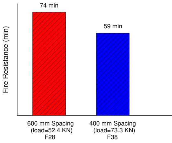
Effect of Stud Spacing
To investigate the effect of stud-spacing on fire resistance, two tests were conducted on steel stud walls F28 and F38. The stud-spacing in Wall Assembly F28 was 610 mm while in F38 it was 406 mm. The assemblies were loaded with corresponding specified loads, calculated based on relevant stud-spacing. The failure in Assembly F28 occurred at 74 minutes while in Assembly F38, the failure resulted in 59 minutes (see Figure 11). These results indicate that stud-spacing has an influence on fire resistance of load-bearing steel stud walls [14].
For a given specified load per stud, wider stud-spacing results in smaller total test load (due to fewer studs in the assembly). Since the wall specimens are loaded between rigid beams, the two cooler studs at wall ends are largely responsible for resisting this total load during the final phase of the fire test. Therefore, a reduction in total load significantly improved fire resistance of Wall Assembly F28. Further research is needed to quantify the influence of this factor on load-bearing walls [4,13].
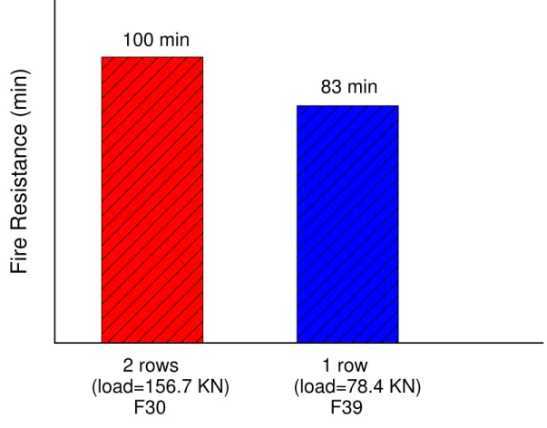
Effect of Stud Rows
Results from fire resistance tests F30, F30R and F39 can be used to assess the effect of the number of rows of studs on the fire resistance of load-bearing steel stud walls. The single row Wall Assembly F39 was loaded with 78.4 kN while the double row wall assemblies was loaded with 156.7 kN. The failure in Wall Assembly F39 occurred at 83 minutes while the failure of Wall Assemblies F30 and F30R occurred at 100 and 102 minutes, respectively (see Figure 12). These results suggest that the uninsulated double
row steel stud walls have higher fire resistance compared to single row steel stud walls. However, it should be noted that there are slight differences, such as arrangement of studs, between the double row and single row stud walls [9]. The higher fire resistance in double row steel stud walls could be attributed to the larger cavity of the wall assembly which create a larger heat sink.
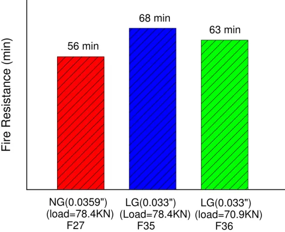
Effect of Steel Thickness
Results from fire resistance tests on steel stud Wall Assemblies F27, F35 and F36 can be used to determine the influence of steel thickness of studs on the fire resistance. Wall Assembly F27 was fabricated from “MSG 20” (Manufacturers Standard Guage) studs with a nominal bare steel thickness of 0.912 mm, while Assemblies F35 and F36 were fabricated from “MSG 20 light” studs with 0.84 mm steel thickness. The applied load on Assembly F27 was 78.4 kN, which represents 90.5% of full specified load based on 0.912 mm thickness of steel studs, but full specified load based on 0.84 mm thickness of steel studs. To establish the influence of steel thickness of studs and load intensity Assemblies F35 and F36 were loaded with 100% (78.4 kN) and 90.5% (70.9 kN) of full specified load respectively, calculated based on 0.84 mm thickness of steel studs.
The failure in Assembly F27 occurred in 56 minutes while in wall Assemblies F35 and F36 the corresponding failure times were 68 and 63 respectively (see Figure 13). These results indicate that walls with “MSG 20 light” studs provide better fire resistance compared to the walls with “MSG 20” studs. Also, test results show that Assembly F35, despite slightly increased load (100% of full specified load), has higher fire resistance than Wall Assembly F36 (with 90.5% of full specified load). This might be due to varying yield strengths of the steel studs from different batches. The results from these fire resistance tests indicated that a small increase in load (about 10% of full specified load) does not significantly alter the fire resistance of steel stud walls.
Repeatability
As a measure of the repeatability of the results, the fire resistance test on Wall Assembly F30 was repeated (F30R). All the parameters in the assemblies were kept the same. Assemblies F30 failed at 100 minutes while Assemblies F30R failed at 102 minutes (see Figure 14). These results indicate that the repeatability of testing full-scale wall assemblies in the NRC furnace is within the tolerance limit of 2 minutes.
CONCLUSIONS
The following points summarise the results presented in this paper. It should be noted that the conclusions apply within the test parameters described in this paper.
1. The type of insulation had significant effect on the fire resistance of load-bearing steel stud walls. Wall assembly without insulation provided higher fire resistance compared to an insulated assembly. Furthermore, the use of rock fiber insulation provided a higher fire resistance compared to glass fiber insulation, but a lower fire resistance compared to cellulose fiber insulation.
2. The number of gypsum board layers had significant effect on fire resistance of load-bearing steel stud walls, with double layers of protection, having much higher fire resistance than single layer protection.
3. In load-bearing gypsum board protected steel stud wall assemblies, replacing a gypsum board layer with OSB shear membrane, resulted in a significant decrease in the fire resistance of the assembly.
4. The double row staggered steel stud walls had higher fire resistance compared to single row steel stud walls.
5. For the load-bearing steel stud wall assemblies, installation of resilient channels, on the fire-exposed side, marginally decreased fire resistance.
6. Steel stud walls with “MSG 20 light” studs provided slightly higher fire resistance compared to the walls with “MSG 20” studs.
REFERENCES
1. National Building Code of Canada (Part 9), National Research Council Canada, Ottawa, 1995.
2. Gerlich, J. T., Collier, P. C. R., and Buchanan, A. H., “Design of Light Steel-Framed Walls for Fire Resistance”, Fire and Materials, Vol. 20, No. 2, 1996, pp. 79-96.
3. Kodur, V.K.R., Sultan, M.A. and Alfawakhiri, F., "Fire resistance of load-bearing steel stud walls", Proceedings, Third International Conference on Fire Research and Engineering, Chicago, IL., U.S.A., 1999, pp.275-286.
4. CAN/ULC-S101-M89, Standard Methods of Fire Endurance Tests of Building Construction and Materials, Underwriters' Laboratories of Canada, Scarborough, Ontario, 1989.
5. CSA-S136-94, Cold Formed Steel Structural Members, Canadian Standards Association, Etobicoke, ON, December 1994.
6. CAN/CSA-A82.27-M91, Gypsum Board Building Materials and Products, Canadian Standards Association, Rexdale, Ontario, 1991.
7. ASTM C36-97, Standard Specification for Gypsum Wallboard, American Society for Testing and Materials, West Conshohocken, PA, June 1997.
8. CSA-A101-M83, Thermal Insulation, Canadian Standards Association, Rexdale, Ontario, 1983.
9. Kodur, V.K.R., Sultan, M.A., Latour, J.C., Leroux, P., and Monette, R.C., "Experimental Studies on the Fire Resistance of Load-bearing Steel Stud Walls", Research Report, IR 833, Institute for Research in Construction, National Research Council of Canada, Ottawa, ON, 2003.
10. CAN/CSA-A82.31-M91, Gypsum Board Application, Canadian Standards Association, Rexdale, Ontario, 1991.
11. Lie, T.T. and Berndt, J.E., “Remote Measurement of Large Deflections in Fire Tests”, Division of Building Research, National Research Council Canada, Building Research Note No. 84, 1972.
12. Shorter, G. W. and Harmathy, T. Z., "Fire Research Furnaces at the National Research Council, Fire Study No. 1”, Division of Building Research, National Research Council Canada, NRC 5732, 1960.
13. ASTM E119-95a, Standard Test Methods for Fire Tests of Building Construction and Materials, American Society for Testing and Materials, West Conshohocken, PA, June 1995.
14. Alfawakhiri, F., Sultan, M.A. and Kodur, V.K.R., "Load-bearing LSF walls exposed to standard fire," Proceedings: CSCE 3rd Structural Speciality Conference, 114-121, London, Ontario, 2000.
ACKNOWLEDGEMENTS
This research is part of a consortium project on the fire resistance and sound performance of wall assemblies being carried out at NRCC. The authors appreciate the technical and financial contributions of Canadian Home Builders Association, Canadian Sheet Steel Building Institute, Canadian Steel Construction Council, Canadian Wood Council, Cellulose Insulation Manufacturers Association of Canada, Forintek Canada Corp.,Gypsum Manufacturers of Canada, Owens-Corning Canada, Roxul Inc., Institute for Research in Construction
Table 1. Test Parameters and Fire Resistance Results for Steel Stud Wall Assemblies Assembly Number Stud Rows Shear Resistance Bri-dging Stud Spacing Gypsum Board Layers Gypsum Board Thickness2 Insulation Type Resilient Channel Applied Load+ Fire Resistance Mode of Failure Mem-brane Cross Brac-ing (mm) (Exp/ Unexp.) (mm) (kN) (min) F25 2 - Y Y 406 1x1 15.9 - - 156.7 35 LB F26 2 - Y Y 406 2x2 12.7 RFI - 156.7 84 LB F27 1 - Y Y 406 2x2 12.7 GFI Y 78.4 56 LB F28 1 - Y Y 610 2x2 12.7 RFI Y 52.4 74 LB
F29 1 Y1 Exp. - YUnexp. 406 1x2 12.7 GFI Y3 Unexp 78.4 33 LB
F30 2 - Y Y 406 2x2 12.7 - - 156.7 100 LB/OB F30R 2 - Y Y 406 2x2 12.7 - - 156.7 102 LB/OB F31 1 - Y Y 406 2x2 12.7 CI Y 78.4 71 LB F34 1 - Y Y 406 1x1 15.9 RFI - 78.4 31 LB F35* 1 - Y Y 406 2x2 12.7 GFI Y 78.4 68 LB F36* 1 - Y Y 406 2x2 12.7 GFI Y 70.9 63 LB F37 1 - Y Y 406 2x2 12.7 - Y 78.4 77 LB F38 1 - Y Y 406 2x2 12.7 RFI Y 78.4 59 LB F39 1 - Y Y 406 2x2 12.7 - - 78.4 83 LB Y – Yes kN – Kilo Newton Y1 – 12.7 mm OSB
2 – Type X Gypsum Board
Y3 – Unexposed side
GFI – R-12, Glass Fiber Insulation RFI – R-13, Rock Fiber Insulation
CI – Cellulose Fiber Insulation – dry blown
Exp. – Fire Exposed Side Location; Unexp. – Unexposed Side Location
LB – Local Buckling (Structural Failure); OB – Overall Buckling (Structural Failure)
Note: *All steel studs in wall assemblies F35, F36 are "MSG20 Light" with nominal 0.84 mm bare steel thickness All steel studs in all other wall assemblies are "MSG20" with nominal 0.912 mm bare steel thickness + The service load level was 90.5% on all steel stud wall assemblies, except F35 where it was 100%
List of Figures
Figure 1. Typical Steel Stud Framed Wall Assembly Layout. Figure 2. Cross-Section Details for Typical Wall Assemblies. Figure 3. Full Scale Wall Furnace Test Facility.
Figure 4. Steel Stud Wall Assembly after Fire Resistance Test. Figure 5. Measured Temperature Distributions in Wall Assemblies. Figure 6. Measured Deflections in Wall Assemblies.
Figure 7.(a) Effect of Insulation Type on Fire Resistance of Single Row Steel Stud Walls. Figure 7.(b) Effect of Insulation Type on Fire Resistance of Double Row Steel Stud Walls. Figure 8. Effect of Resilient Channel on Fire Resistance.
Figure 9. Effect of Shear Membrane on Fire Resistance. Figure 10. Effect of Gypsum Board Layers on Fire Resistance. Figure 11. Effect of Stud Spacing on Fire Resistance.
Figure 12. Effect of Number of Rows of Studs on Fire Resistance. Figure 13. Effect of Steel Stud Thickness on Fire Resistance. Figure 14. Repeatability of Fire Resistance Results.
0 5 10 15 20 25 30 35 40 45 50 55 60 65 70 75 80 85 90 0 100 200 300 400 500 600 700 800 900 T 1000 e m p e r a t u r e ( C ) Furnace T t FL/BL (E ) BL/Cav. (E ) Hot Flange Cold Flange Unexposed Sid BL/FL (U E ) Cav./BL (U E ) Web Wall Assembly F27 0 5 10 15 20 25 30 35 40 45 50 55 60 65 70 75 80 85 90 0 100 200 300 400 500 600 700 800 900 1000 T e m p e r a t u r e ( C ) Furnace T t FL/BL (E ) BL/Cav. (E ) Hot Flange Cold Flange Unexposed Sid BL/FL (U E ) Cav./BL (U E ) Web Wall Assembly F28 0 5 10 15 20 25 30 35 40 45 50 55 60 65 70 75 80 85 90 Time 0 100 200 300 400 500 600 700 800 900 1000 T e m p e r a t u r e ( C ) Furnace T t FL/BL (E ) BL/Cav. (E ) Hot Flange Cold Flange Unexposed Sid BL/FL (U E ) Cav./BL (U E ) Web Wall Assembly F31
Exp. = on exposed side UnExp. = on unexposed side)
0 5 10 15 20 25 30 35 40 45 50 55 60 65 70 75 80 85 90 -50 -40 -30 -20 -10 0 10 20 30 H 40 50 o r iz o n t a l D e fl e c ti o n ( m m ) Mid-height 75% Height L l 25% Height L l Wall Assembly F27 0 5 10 15 20 25 30 35 40 45 50 55 60 65 70 75 80 85 90 -50 -40 -30 -20 -10 0 10 20 30 40 50 H o r iz o n t a l D e fl e c ti o n ( m m ) Mid-height 75% Height L l 25% Height L l Wall Assembly F28 0 5 10 15 20 25 30 35 40 45 50 55 60 65 70 75 80 85 90 Time (min.) -50 -40 -30 -20 -10 0 10 20 30 40 50 H o r iz o n t a l D e fl e c ti o n ( m m ) Mid-height 75% Height L l 25% Height L l Wall Assembly F31