An Automated Verification Tool for Expert Systems
by
Alexandra Y. Pau
Submitted to the Department of Electrical Engineering
and Computer Science in partial fulfillment of the
require-ments for the degree of
Bachelor of Science and Master of Engineering in
Electri-cal Engineering and Computer Science
at the
MASSACHUSETTS INSTITUTE OF TECHNOLOGY
May 28, 1996
© Copyright 1996 Alexandra Y. Pau. All Rights Reserved.
The author hereby grants to M.I.T. permission to
repro-duce distribute publicly paper and electronic copies of
this thesis and to grant others the right to do so.
Author
...epeint[L1.uI•L
nu.
ilctL Lau, lmmuginiiiug auuL.,unpater
Science
May 3, 1996
Certified by
...... ,. Kenneth Haase
MIT Media Laboratory
Thesis Supervisor
A cc
...
rgenthaler
...
_U,.-
,
...
.
V.... .--
ate
Thesis
AssAc•-usErrs NST'Iu06LElectrical
Engineering
and Computer Science
OF TECHNOLOGY
JUN
111996
An Automated Verification Tool for Expert Systems
by
Alexandra Y. Pau Submitted to the
Department of Electrical Engineering and Computer Science May 7, 1996
In partial fulfillment of the Requirements for the Degree of Bachelor of Science in Electri-cal Science and Engineering and Master of Engineering in ElectriElectri-cal Engineering and
Computer Science
Abstract
The automated verification tool is developed to help users in building or modifying a rule-based expert system. The design of this tool differs from that of other verification tools in two major components. First, this tool provides a front-end to existing expert system shells. Users interact with their expert system through a user-friendly interface. All rules are entered in simple "if-then" statements rather than an expert system shell language. Verification is performed in meta-language before the rules are translated to any specific expert system language. In addition, the tool provides a visual representation of the state of a knowledge base. The inference relationship among rules of a knowledge base is illus-trated by a directed graph. The tool automatically performs verification and syntax check-ing. Users are notified of errors and conflicts through popup message windows and by highlighting nodes in the graphical analyzer.
Thesis Supervisor: Kenneth Haase Title: MIT Media Laboratory
ACKNOWLEDGEMENT
I would like to thank my group supervisor at JPL, Ursula Schwuttke, for giving me the opportunity to work on this project and for her guidance through my internship there. I also want to extend my sincere thanks to Bonnie Traylor, my mentor for this project. Thank you for your patience, your suggestions, and your company. Many thanks to Diana Hamilton and the whole AEG gang for making my internship a fun learning experience. I am very grateful to my thesis advisor, Kenneth Haase, for his input and suggestions. He guided me through my research project, from providing me background resources to proof-read my thesis write-up.
I especially want to thank my parents for their unfailing support and encouragement. You sacrifice so much so that I can pursue my dreams. Thank you for everything.
Many thanks to my friends and CCF for making MIT a memorable experience. Last but not least, a big thanks to Him who made all these possible.
Table of Contents
1 Introduction ... 10 1.1 Expert System s...10 1.2 Expert System s at JPL ... 10 1.3 Proposed Solution ... ... ... 12 2 Background ... ... 14 2.1 Previous W ork ... ... 142.2 Background on Verification Algorithms ... ... 16
3 A pproach... ... 18
3.1 The D esign ... ... 18
3.2 Graphical U ser Interface (G UI) ... 19
3.3 Parser... 21
3.4 V erification ... 22
3.5 Automated Graphical Analyzer ... ... 25
4 Experimental Evaluation...32
4.1 Guidelines for Evaluation ... . ... 32
4.2 Insurance Plan A dvisor ... 32
4.3 FD IR Boresight ... ... 37
5 Conclusion ... ... 40
5.1 Successes...40
5.2 Failures...40
6 Future W ork ... 42
6.1 Feature Im provem ents ... 42
6.2 A uthor's Com m ents ... 42
Bibliography ... 44
Institute Archives and Special Collections Room 14N-118
The Libraries
Massachusetts Institute of Technology Cambridge, Massachusetts 02139-4307
There is no text material
Pages have been
missing here.
incorrectly numbered.
List of Figures
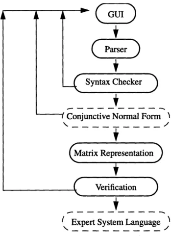
Flow chart for the design of verification tool for expert systems ... 18 Graphical user interface for the automated verification tool...20 Calculating the intersection positions of the nodes and their connecting
edge ... 30 Pop up message window displaying verification result for Insurance
Plan Advisor... ... ... 33 Graphical analyzer for the rule base of the Insurance Plan Advisor ... 34 Pop up message window displaying the verification result of the
modified Insurance Plan Advisor system ... 36 Graphical analyzer for the rule base of the modified Insurance Plan
A dvisor system ... 37 Pop up message window displaying verification result for Boresight. ... 38 Graph analyzer for the rule base of Boresight system...39 Figure 3.1: Figure 3.2: Figure 3.3: Figure 4.1: Figure 4.2: Figure 4.3: Figure 4.4: Figure 4.5: Figure 4.6:
Institute Archives and Special Collections Room 14N-118
The Ubraries
Massachusetts Institute of Technology Cambridge, Massachusetts 02139-4307
There is no text material missing here.
Pages have been incorrectly numbered.
Institute Archives and Special Collections Room 14N-118
The Libraries
Massachusetts Institute of Technology
Cambridge, Massachusetts 02139-4307
There is no text material missing here.
Pages have been incorrectly numbered.
Institute Archives and Special Collections Room 14N-118
The Libraries
Massachusetts Institute of Technology Cambridge, Massachusetts 02139-4307
There is no text material missing here.
Pages
have been
incorrectly numbered.
Institute Archives and Special Collections Room 14N-118
The Libraries
Massachusetts Institute of Technology Cambridge, Massachusetts 02139-4307
There is no text material missing here.
Pages have been incorrectly numbered.
Chapter 1
Introduction
1.1 Expert Systems
Expert systems have been widely used in industry, business, medicine, and government. The applications of expert systems have been increasingly broad, and include certain generic benefits such as providing expertise where it is scarce, speeding up analysis time, and collectively capturing and preserving knowledge from the top experts in a field. Almost all existing expert systems in use are task specific. That is, they are built for one specific narrow domain task. Traditionally, all theoretical research, software tools, and expert system languages are developed for specific applications. One drawback of these systems is that they are built in a specific expert system language and, therefore, cannot readily be used for other tasks even if the goals of the tasks are similar and same methods and algorithms apply. The development cycle of an expert system is usually long and com-plex, from data acquisition to verification and validation. More and more, engineers are exploring general application expert systems and tools for aiding expert system develop-ment, to save time and resources, and to shorten the development cycles.
1.2 Expert Systems at JPL
At the NASA's Jet Propulsion Laboratory, embedded rule-based expert systems are widely used for real-time data monitoring, diagnosis of system anomalies, and preserving exper-tise of spacecraft analysts and operation specialists. In the new age of "faster, better, cheaper" missions, developing systems quickly and cost efficiently is heavily emphasized. Traditionally, expert systems at JPL are built individually for their specified tasks. A
typi-cal expert system takes more than a year to develop. In developing an expert system at JPL, the scientists or engineers define the specifications and objectives of a system. The specifications are then passed on to software engineers who often are not familiar with the domain of knowledge that is to be captured in an expert system. As a result, a large portion of software engineers' time is spent in acquiring and understanding the specifications given to them. This building process is time consuming and cost-inefficient. In addition, all expert systems are built in a limited time frame. Updating expert systems after they have been put to use is inevitable, be it adding new rules or changing existing rules. The system updating process usually involves rehiring the original software engineers who developed the system. However, these software engineers have already moved on to other projects. They often cannot be found or are not available to take on the updating task immediately. An alternative is to hire any available software engineers. But they would have to spend time to learn the background knowledge of the system. Either way, the pro-cedure is impractical and time-consuming.
Methods for reducing the development cycle of expert systems are in high demand. Most of the inefficiency in a system development cycle occurs during the knowledge transfer between the experts and the software engineers. The experts provide the detailed guidelines of system performance, and the software engineers translate these guidelines to an expert system. Eliminating the role of software engineers in expert system development can reduce the development cycle time significantly. Software engineers are not needed if the development task is in the hands of the experts who know the particular domain of knowledge.
The software engineers are necessary in traditional expert system development for two major reasons. First of all, expert systems are developed in expert system shell languages. The commercially available shell languages are designed similarly to other programming
languages and are often too complicated for non-programmers. The scientists/engineers using the systems often do not have the time or willingness to learn an expert system lan-guage needed to develop or upgrade an expert system. In addition, verification and valida-tion is the most complex aspect of expert system development. Even experienced software developers are concerned with successful verification of the system. It is too complicated for experts from JPL, who are non-programmers, to verify an expert system. Verification and validation are critical to the success of an expert system. Unfortunately, the verifica-tion capability provided by most commercial shells is limited to syntax check and type validation, leaving most of verification in the hands of the developers. As a result, soft-ware engineers usually are hired to collect the necessary knowledge from the experts and then translate it to a functional expert system. However, the experts providing the knowl-edge for the system often have other responsibilities, the knowlknowl-edge transfer from the experts to the software engineers is ad-hoc and expand over a period of weeks and months. A major portion of the system development time is spent in transferring knowl-edge from the experts to the software engineers, rather than in coding the specifications to the expert system. In addition, misunderstanding and misrepresentation often occur during knowledge transfer between the experts and software engineers due to inadequate commu-nication skills and the software engineers' lack of understanding of the knowledge domain.
1.3 Proposed Solution
We propose an automated tool for building and verifying expert systems characterized by rules adhering to grammar restrictions imposed by the meta-language. The tool plays the role of software engineers in conventional expert system developments. It will allow experts to program an expert system themselves by entering rules through a user-friendly
interface in simple IF-THEN rule statements. The tool will automatically perform verifica-tion such as checking for misspelling, inconsistency in variable declaraverifica-tion, rule conflicts, and duplicated rule names. More over, a graphical analyzer supplements the above auto-mated verification. It visual displays the inference relationship among the rules in the rule base, with arrows going from one rule to another indicating the inference sequence in the rule base. A user can easily analyze the inference relationship of the rule base by looking at the graphical display, then edit rule and re-verify the rule base until the rule base until the analyzer displays the desired inference pattern. After completing the verification, the rules are then translated into an expert system shell language.
The design of this tool promises a large degree of flexibility. Since all verification is done in a knowledge base internal to the tool called meta-knowledge, the tool is indepen-dent of any expert system language. It can be easily adopted for expert systems in any shell language by providing a simple interface that translates the verified rules into an expert system shell language of choice. In addition, with an automated verification module that displays inference relations among the rules in a rule base, users with little or no knowledge of expert system languages and expert system developments can build systems without external help, and with more confidence than with conventional expert system shells, which require complex programming expertise and extensive verification and vali-dation.
Chapter 2
Background
2.1 Previous Work
An expert system that works for an interesting domain cannot be completely analyzed automatically, either because not enough semantic information is provided, or because there are questions that cross the undecidability barrier (Landauer, 1989). In the process of building an expert system, extensive tests and evaluations of the system is conducted throughout all stages of development. The procedure of testing to make sure that the sys-tem is operating according to its pre-defined criteria is called verification and validation.
Verification and validation are performed at various stages of development. There is semantic verification, a simple check of spelling and value types; static analysis, checking for redundant clauses and rules; inference analysis, checking for conflict rules, isolated rules, and circularity in inference rules. Verification is the act of comparing the expert sys-tem's result for a given problem in the domain with answers provided by experts of the field to verify that the system is producing the right answer. Therefore, verification often requires detailed knowledge of the system being built, and cannot be easily generalized. However, a major portion of verification for rule-based systems can be automatically per-formed by the expert system building tool because it involves analysis of the syntax, struc-ture, and inference of the rules of first-order logic.
Extensive research has been conducted in verification and validation of rule-based expert systems. Hundreds of papers on verification and validation algorithms and tools have been published in the past. Some algorithms are purely theoretical arguments and were never evaluated in actual applications; some were implemented in expert systems
that work for narrow domains only. Few tools for aiding expert system development exist in the growing field of expert system community. There are no applicable tools that meet demands of the highly specialized expert systems in JPL.
The expert systems described below are typical expert systems. We will examine the verification and validation methods used and the systems' performance.
The Rule Checker Program (RCP) was developed at Stanford University in 1982. It was developed as part of the ONCOCIN project and thus is application-specific. It has the ability to check knowledge bases solely on the basis of their syntax. It can also check a knowledge base in the absence of an inference engine. However, it makes certain assump-tions about the rule base. For example, it assumes the reasoning of the rule base is mono-tonic, rules conclude certain value for a given item of data, and all rules are assigned to particular context which tells the inference engine when to fire the rules. RCP takes on an exhaustive approach in verification. For example, the deficiency check of RCP checks to see if every possible permutation of the parameters and their values is covered by some rule in the table. This method of checking becomes intractable for systems with large rule base.
The CHECK program was developed at Lockheed corporation in the mid 1980s as a verification module for their expert system shell language, called the Lockheed Expert System (LES). LES is a rule-based tool containing both forward-chaining rules and back-ward-chaining rules. Similar to RCP, the verification of CHECK program is based on three cache tables, the "if-if' table, the "then-then" table, and the "then-if' table. The entries of these tables are created by comparing the clauses of each pair of rules. For a system of n rules, it performs n*(n-1)/2 comparisons for each table.
The Expert System Validation Associate (EVA) system was a long term project at Lockheed Corporation to develop a general-purpose verification and validation tool for
expert systems. EVA was built in Prolog, but is not tied to any particular rule language or expert system shell language. It provides a set of translation programs which translate the rule languages of several widely used shells to an internal form based on first-order logic. EVA is one of the few tools that attempts to create a general-purpose verification and validation. It also includes translation programs to convert rules from other shell lan-guages to Prolog. However, it is unclear as to how much of their described features were implemented or how successful the project was (Preece, 1992).
All verification tools developed thus far are intended to aid software engineers in designing expert systems. They are developed in one particular shell language and incom-patible with other shell languages. EVA attempts to make the tool more portable by pro-viding translation programs from other shell languages to Prolog. Nevertheless, the development environment is still in an expert system shell language. This research project attempts to build an automated verification tool that is independent of any expert system shell language and provide extensive aid in verification. The development environment will be in simple IF-THEN English statements, independent of any shell language. Thus, users with little programming experience and unfamiliar with verification procedure can program an expert system using this tool. Furthermore, this tool provides capabilities to aid developers analyze inference sequences and the relations among rules in a rule base.
2.2 Background on Verification Algorithms
Many methods of verification and validation for rule-based systems have been developed in recent years. The most popular models used for verification are mathematical approach and linguistic approach. The linguistic approach checks a rule base for correctness by ana-lyzing the syntax and semantics of its use of language. Most of them are variations of
exhaustive comparisons in which each clause is checked against all other clauses in the rule base (Preece, 1992). The computation time of this approach grows in proportion to the combinatorial of total number of rules. The verification becomes impractical for large rule base systems. The mathematical approach analyses the structure of a rule base, which reflects the logical processes behind an expert's reasoning. The mathematical approach is more precise and rigorous. The verification algorithm for this research project is based on the mathematical model.
Verification is an evaluation of a rule base correctness in comparison to a specification of its desired behavior. There is a substantial amount of published work in verification of rule-based expert systems. Unfortunately, there is no one established guideline of criteria and definition for verification in the literature. All researchers define and follow their own verification criteria and authors use their own terminologies to express the concept of ver-ification. However, the different terminologies fundamentally come down to five basic principles:
* Consistency, making sure that there are no conflicts among rules. All situations
should be well defined. For example, two rules consisting of same antecedent clauses have to draw same conclusion statements.
* Completeness, checking for universal applicability of the rule base. That is, the rule
base should be able to draw conclusion for any situation in its defined domain.
* Irredundancy, assuring that everything in the rule base is there for a good reason. No
variables, no clauses, and no rules are redundant.
* Connectivity, analyzing groups of rules for the entire dynamic process of inference.
The interaction among the rules in any situation should be proper.
* Distribution, checking for even distribution in usage of rules in the rule base. Any
instance should only have inference to a small portion of the rules. Similarly for a given variable, the set of rules accessing that variable should be a small subset of the rule base.
All verification criteria discussed in published papers can be categorized under a
sub-set of the above five principles. A large portion of the mentioned verification criteria can only be performed with additional knowledge of the specific rule-based system. For exam-ple, the missing rules criteria can only be tested if the goals of the system is known. How-ever, by analyzing the structure of rules and the inference relationships among the rules, certain types of error checking can be performed solely based on the rules in a rule base, without additional knowledge of the system. These verification criteria that depend only
Chapter 3
Approach
3.1 The Design
GUI
ParserSyntax Checker
cc~
_Sonjuncuve iormal rorm
(Matrix Representation
Verification
' Expert System Language '
Figure 3.1: Flow chart for the design of the verification tool for expert systems
The primary goal of this project is to develop a protocol application to aid users with no programming background to develop rule-based expert systems on their own, without the help of experience software engineers. Alternatively, this tool will enable JPL engi-neers and scientists to add or change rules in a rule base by themselves, without wasting time and resources to track down the original system developers. With this emphasis in
mind, we developed an automated verification tool for real time rule-based expert systems called SOCRATES.
The design of this application reflects three major differences between this tool and other existing ones. First, the application allows experts with little or no programming experience to build knowledge-based systems on their own, through a user-friendly inter-face, without the help of software engineers. Second, the verification module is self-con-tained and independent of any expert system shell language. All of the verification are done in the meta-language, before the rules are translated into a shell language for execu-tion. Performing verification in a self-contained meta-language provides portability across various expert system languages in different platforms. The third and most significant fea-ture is its graphical analyzer. The graphical analyzers are automatically generated by the application to display the relations among the rules of a rule base graphically in a flow-chart style for easy comprehension.
In building an expert system using SOCRATES, users insert and edit rules through a user-friendly GUI. Each rule is parsed and then checked for simple syntax errors and duplication (in rule name only). If the rule has no syntax error and the rule name does not exist already, it is entered into the rule base and meta-knowledge. Once the user has fin-ished entering all the rules and press the verification button on the pull-down menu bar, the tool generates several incidence matrices. Upon completing the verification, a graphi-cal analyzer window will appear displaying all rules (represented by nodes) and the rela-tionship among the rules (represented by a line with an arrow indicating the direction of the inference). If additional changes are needed, the user can add more rules through the rule editor on the GUI, and re-process the changes. Once all changes are completed, the user can generate it into an expert system language of his choice. All of the above proce-dures are performed in real-time.
The feature of translating a rule base into an expert system language is not imple-mented in this project due to time constraint. It is a simple syntax translation that can be added once the desired shell language to convert into is known.
3.2 Graphical User Interface (GUI)
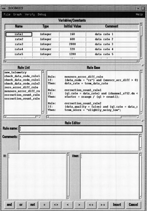
The graphical user-interface consists of a constant/variable window, a rule index column, a rule base window, and a rule editing window (see Figure 3.2). The constant/variable window is for declaration of variables, their type, and their initial values. The rule index column displays the names of all rules in the rule base for easy access. The rule base win-dow displays complete rules inserted in the rule base. The rule-editor winwin-dow is divided into a rule name field, a comments field, a IF field, and a THEN field. The tool only accepts a rule if it is complete, that is, if it has a rule name, if clauses, and then clauses.
The GUI is divided into three expandable sections: top for constant/variable window, middle for rule index and rule name, and bottom for rule editor window. The user can choose the size of each window by clicking on one of the two divider lines and move it up or down.
Each window and each field within that window has its own editing functions in a popup menu. The constant/variable window has insert row, delete row, copy and paste row, and delete cell. The rule index field has search (to find a particular rule in the rule base) and delete (for removing a rule from the rule base). All fields in the rule-editor win-dow have copy, paste, and delete.
rate2 rate3 rate4 rateS ew_ceieme-ry theck_data_code_rulel. :heckdatacoderule I heckdatacoderule2. oeroerrordiffrule
onzero error diffru
-orrection_countrule -orrection_count_rule integer integer integer integer Rule: If: Then: 600 2800 320 1280 eara data data data data rate rate rate rate rate nonzero_error_diff_rule
(datacode = "rs") and (uncorrerr_diff > 0)
data_rate = tcomkdata_rate
Rule: correction countrulel
If: (ql.rate =:datasrate) and (channel_s752.dn < Then: sfactor = srange / (ql > countl);
Rule: correction_countrule2
If: (data-quality = false) and (ql.rate
Then: tcom_score = "slightly_noisy_1w"; = data_i
Figure 3.2: Graphical User Interface for the Automated Verifcation Tool
i- - - -
-I
The constant/variable window is in the format of a table with four columns: Name,
Type, Initial Value, and Comments. The column Name allows input in any combination of
characters as long as it is not a number. The input to column Type is validated as it is entered to ensure that it is one of the three allowable values: STRING, FLOAT, and INTE-GER. The input to column Initial Value is validated against the value in its corresponding
Type column to make sure they are consistent.
The rule name field and the rule base display field adjust automatically to guarantee that the most currently inserted rule is shown in the viewing window.
The rule-editor window performs simple syntax check and duplicate rule name check as a rule is inserted in the rule base. It also ensures that the entered rule is complete, in other words, it has a name, an IF statement, and a THEN statement. If a rule is unaccept-able, a message window will popup explaining the reason why the rule is not inserted into the rule base.
3.3 Parser
3.3.1 Domain of the Parser
All inputs are entered in one of the two formats, either as variable declaration through the variable/constant window or as a simple rule through the rule-editor window. The inputs are parsed and stored in data structures after they are entered. Some basic checks, such as duplicated rule names, syntax errors, and illegal variable assignments are performed on a rule when it is parsed. If the rule is error-free, then it is added to the rule-base and to the data structure. A permissible input rule has to be in the form of IF-THEN statement, with a rule name, if clause, then clause, and an optional comments section. The parser also ver-ifies that the input is in the form of standard first-order logic.
3.3.2 Lex and Yacc
The parser is programmed in Lex & Yacc. Lex & Yacc are tools often used for writing compilers and interpreters. Their specialty is looking for patterns in the inputs. It is con-cise, readable, and thus easy to edit and maintain. When user presses the insert button, a C program extracts the input rule from the GUI and passes the string to Yacc. Yacc in turn
calls Lex to identify tokens (break the input string down into recognizable patterns). If the parser cannot break it down into recognizable patterns, it returns a syntax error to notify the user. Otherwise, it stores the string in a data structure according to pre-defined patterns either through the variable/constant window or the rule-editor window.
3.4 Verification
3.4.1 The Inference Engine
In a rule-based expert system, the set of known facts at an instant in time is called a sit-uation. The inserted initial facts combined with the rules shift the rule base from one situ-ation to another. The action is called rule inference. The possible inference ordering in the
rule base is called the inference engine.
3.4.2 Verification Criteria
Verification is the static and dynamic analysis of the logic of knowledge to reveal potential errors (Preece, 1992). Since this research project is an expert system building tool, no knowledge is assumed beyond the entering rules. Thus, only three of the five
prin-ciples can be tested: redundancy, consistency, and connectivity. Redundancy include
iso-lated rules, duplicated rules, and subsumed rules. Isoiso-lated rules are the unusable rules in a rule base that is neither inferenced by any other rule nor inference to any other rule. Two rules are duplicated if they have identical clauses both in hypothesis and in conclusion. Rule A is subsumed by Rule B if the hypothesis of Rule B is a subset of the hypothesis of Rule A, and rules A and B have identical conclusions. Consistency implies there are no
conflicting rules. Two rules in a rule base are conflicting if they fire under the same situa-tions yet draw different conclusions. Connectivity principle tests for circularity and miss-ing rules. A rule base has circularity if it contains some set of rules that an interminable loop could occur when the rules are inferenced. Missing rules only can be detected when the goal states of the expert system is known. Since this is a general application tool, not a specific expert system, the goal states of a particular system are unknown. Therefore, missing rules criteria cannot be verified automatically. However, at the time of building a
specific system, a user has knowledge about the system beyond just the rules, such as the goal of the system and the domain of the system. Therefore, missing rule criteria can be evaluated by the user with the aid of the graphical rule analyzer.
3.4.3 Verification Algorithm
Christopher Landauer at The Aerospace Corporation suggested a clever way of model-ing a rule base. The basic idea is to use incidence matrices to represent relationships among the rules. For example, a RV incidence matrix represents the rule-variable relation-ship in the rule base.
RV(i,j) = 1, if variable j is in rule i,
RV(i,j) = 0, otherwise
Similarly, a RC matrix represents the rule-clause relationship of a rule base, and a CV matrix represents the clause-variable relationship of a rule base.
The verification algorithms for this tool is based on Landauer's idea of matrix repre-sentation. Four matrices were built: CC matrix, CH matrix, RVc matrix, and RVh matrix. CC matrix indicates the presence of clauses in the conclusion of all rules. It has rules for the row entries and clauses for the column entries. For example, CC(i,j) indicates whether or not clause j is present in the conclusion statements of rule i. Similarly, row i of CC matrix indicates all clauses in the conclusion of rule i. CH matrix indicates the presence of
clauses in the hypothesis of rules. It also has rules for the row entries and clauses for the column entries. CH(i,j) indicates whether or not clause j is present in the hypothesis of rule i. RVc matrix and RVh matrix are the rule-variable matrices representing conclusion
statements and hypothesis statements respectively. They both have rules for the row entries and variables for the column entries. RVc(i,j) indicates whether or not variable j is present in the conclusion statements of rule i. Similarly, RVh(i,j) indicates whether or not variable j is present in the hypothesis statements of rule i.
Let us define an inference R graph such that inferR = (CC)(CHtr).
InferR is a mxk matrix with rules indexing both rows and columns. A non-zero entry in the inferR matrix implies an inference between two rules in the rule base.
(CC)(CHtr) (i, j) >= 1, if rule i inferences rule
j.
The algorithm works as follow: entry (i,j) in inferR matrix is the product of row i of CC matrix and column j of CHtr matrix. The non-zero entries in row i of CC matrix repre-sent all clauses in conclusion of rule i. Similarly, the non-zero entries in column j of CHt matrix, which is same as row j of CH matrix, represent all clauses in hypothesis of rule j.
Thus, entry (i,j) in inferR matrix is only non-zero when row i of CC matrix and column j
of CHtr matrix have at least one clause in common. 3.4.4 Verification Implementation
Using the inference matrices, the criteria conflict rules, circular chaining, subsumed rules, and isolated rules were tested. Two rules are conflicting if they have identical hypothesis statements (same number of clauses in the hypothesis statements and each pair of clauses are equal) and different conclusion statements. Rule conflicts are checked using CH matrix and CC matrix. Circular chaining occurs when a rule node is a child node of its own children. In terms of graph, circular chain exists if there is a path traveling from a
node to itself with no backtracking. Circular chaining is examined using depth first search. As it traverse through a node, it checks to see if the node has been visited. If the node is not visited, mark it visited; if the node is visited, it is a circular chain. Subsumed rule is a subset of redundancy. One rule is subsumed by another if two rules have identical hypoth-esis statements but the conclusion statements of the first rule is a subset of the conclusion statement of the second rule. An isolated rule may or may not be redundant. It is not redundant if it represents an inference of one level deep. On the other hand, it is redundant if it represents a rule drawing conclusion clauses that are not used anywhere in the rule base and the conclusion clauses are not the goal states. Therefore, an isolated rule could or could not be useful. The tool identifies the isolated rules for the user to decide what to do with it.
3.5
Automated Graphical Analyzer
3.5.1 Visual Representation of Relations Among the Rules
To create a visual representation of the rule base structure, the rules are displayed graphi-cally in directed graph format. Each rule is represented by a node, and inference relation-ship among the rules is represented by a line with an arrow pointing in the direction of inference. An inference matrix of the rules can be easily converted to a graph of the above mentioned format. By making a vertex for each row and column, and an edge for each nonzero entry in the inference matrix, a visual representation of the rule in the rule base can be created. Verifications such as connectivity and distribution can be spotted at a glance on the visual rule analyzer.
3.5.2 Automated Graph Layout Algorithm
The difficulty of an automated graph representation lies in arranging the layout for easy visual interpretation. Basically, given a particular rule base with known relationships
among the rules, how can the vertices be automatically positioned so that there are mini-mum edge crossings? This is the most crucial problem as far as readability of a graph is concerned. There are extensive literature on the research of graph layout algorithms. A simple algorithm called the Relative Degree Algorithm is implemented in this research project. The algorithm was developed by Marie-Jose Carpano and implemented in a project called GTIVX, a computer aided decision analysis tool which facilitate interactive structural systems analysis (Carpano, 1980). The idea behind this algorithm is simple
--the more vertical --the edges are, --the fewer --the crossings. This algorithm assumes that all nodes are assigned a level number. It arranges the order of nodes on a single level by examining their relationship with the nodes one level higher than them and one level lower than them.
Take the simple case of a two-level cycle: free graph where the flow is unidirectional (top to bottom, for example), if all children nodes on the lower level is right below their parent nodes on the top level, there would be no edge crossings. Hence, for every permu-tation on node arrangements of level i, the method consists defining a permupermu-tation of nodes for level (i+1) such that the vertices are placed as directly beneath their parent nodes on level i as possible. This concept can be expressed concisely in the matrix formalization.
Let
xi be a node on level 1 of a two-level graph. yi be a node on level 2 of the two-level graph.
Axy be a m x k boolean matrix indicating the presence of edges from xi to yj. Then,
Axy(i, j) = 1, if there is an edge from xi to yj. Axy(i,j) = 0, if there is no edge from xito yj.
Let
Ax be the matrix obtained by dividing each coefficients aij of Axy by z,kaik and transposing it.
Ay be the matrix derived from Axy by dividing each of its coefficients aij by Ikaik .
X = (x, x2, ..., Xk) be the vector of the x-coordinate of the level 1 nodes.
Y = (y1, y2, ***, Yk) be the vector of the x-coordinate of level 2 nodes. Then,
y(P) = AxX(P )
and
X(P+ ) = A Y(P)
The pth iteration of the x-coordinates for level 1 nodes and level 2 nodes can be calcu-lated using the above equations.
3.5.3 Adopting the Algorithm for Verification Tool
The Relative Degree algorithm mentioned above has three assumptions which does not apply in this Verification Tool.
1. The algorithm assumes that the graph is cycle free.
2. The algorithm assumes an ordered hierarchy graph that flows unidirectionally.
3. The algorithm only applies to a two-level graph.
The input data is filtered to remove all circular paths. Then, each node is assigned a rank number to decide which level of the graph it belongs to. Using depth first search, the first node visited (root node) is in level 0, the next node visited is in level 1, the (i+ 1)th node visited is in level (i+ 1). When a node is visited more than once by various paths, the highest level assignment becomes its new rank. The inference matrix and the ranking
array are then used to calculate the actual positioning of the nodes in the tcl/tk graphical analyzer window.
The Relative Degree algorithm arranges nodes one level at a time for minimum edge crossing. The calculated positions of nodes are used to distinguish the relative position of nodes of the same level. At each level, the nodes are displayed equidistant apart, ordered according to their calculated positions. An additional feature is added which checks for overlapping node replacements. If two nodes have the same calculated position, they will overlap when drawn in the graph analyzer window. When this situation is detected, one of the nodes is moved away so that all nodes have unique positions.
3.5.4 Generating Graphs in Tcl/Tk
Tcl/Tk is a programming language developed by John Ousterhout at the University of California, Berkeley. The syntax is simple and thus easy to use, yet it has very useful graphical facilities. TCL is the basic programming language, and TK is a ToolKit of wid-gets similar to those of Xlib and Motif. Unlike Xlib or Motif, Tcl/Tk is a self contained language that can be executed on its own. But if users wish to use the widgets with other programming languages such as C or C++, the Tcl/Tk system can be configured to work with other programming languages. The main advantage of Tcl/Tk is its simple syntax. A useful application can be developed quickly and concisely in a short period of time, even if the developer is not fluent in Tcl/Tk.
The Tcl/Tk window has a simple manu bar with four submenus: File, Graph, View, and Help. It can print the graph to a file, graph either rules or clauses and their relations, and has an option to show rule names and clause names next to the nodes. The Tcl/Tk dow is divided into two sections: a graph window and a display window. The graph win-dow shows a visual graph of rules in a rule base. The display winwin-dow displays the content
of rules/clauses when a user clicks on a node in the graph window. Both windows have horizontal and vertical scroll bars for viewing purpose.
3.5.5 Calculating the Intersection Position
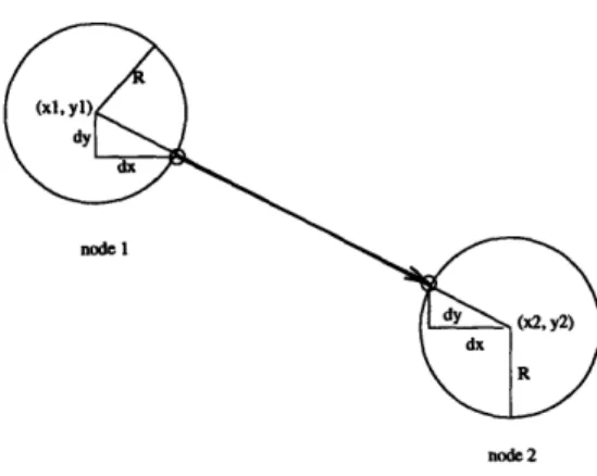
In Tcl/Tk, a line is drawn by specifying the X and Y coordinates of the two end points. Each node, representing a rule, is a solid circle of radius R. Since each node has a surface area greater than zero, it is necessary to calculate where on the circumference of a node does a connecting line intersect. The intersections can be calculated from the relative posi-tions of the two end nodes.
For example, let node 1 be located at (xl, yl) with radius R, and node 2 be located at (x2, y2) with radius R (see Figure 3.3). The distance from center of node 1 to center of
node 2 is calculated by
D= V(xl -x2) 2+ (yl -y2)2
The coordinates on the circumference of node I to node 2 that specifies their connect-ing edge are (xl+dx, yl+dy) and (x2-dx, y2-dy) respectively, where
dx =(x 2-xl) xR
D
and
dy =(y2-yl) xR D
node 1
node 2
Figure 3.3: Calculating the intersection positions between the nodes and their connecting
Chapter 4
Experimental Evaluation
4.1 Guidelines for Evaluation
To evaluate the performance of this tool, it is tested with several rule-based expert sys-tems. Letting a user with no expert system building experience put together a new expert system on the verification tool would be the ideal way to perform a thorough evaluation of the tool. Not can it only evaluate for technical performance, but also for human factor issues like user-friendliness and usefulness of the rule base analyzer. Due to time and resource constraints, the tool was only tested on two existing rule-based systems. The test case systems were already built and put to use. Thus, there are no fatal errors in the sys-tem. However, there are several isolated and maybe redundant rules. In addition, some rules were altered just like a user would when updating an expert system. Some new errors were induced as a result. The altered rule bases are again verified by the automated tool. The errors detected by this automated verification tool will be summarize. The errors include duplicated names, duplicated rules with different names, potential circular infer-ence paths in the rule base, and subsumed rules, and conflict rules, as well as errors that the tool missed. In addition, the visual rule analyzer will be evaluated for visual clarity and its usefulness in providing insights into the rule bases.
4.2 Insurance Plan Advisor
The Insurance Plan Advisor is a small rule-based expert system written in Shrubs. It con-sists of a total of thirty six rules. It decides on a type of investment for the user based on conditions such as whether or not the user has children going to college, the user's stage in
life, the user's savings and properties.
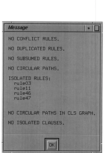
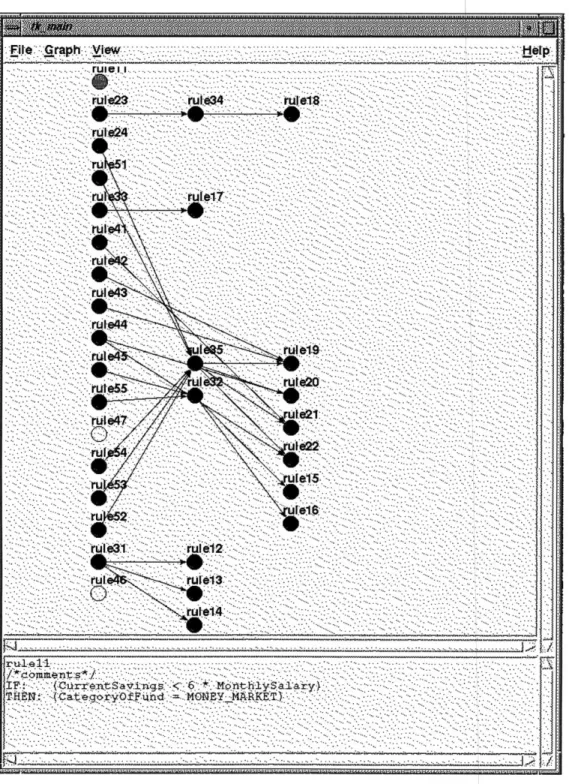
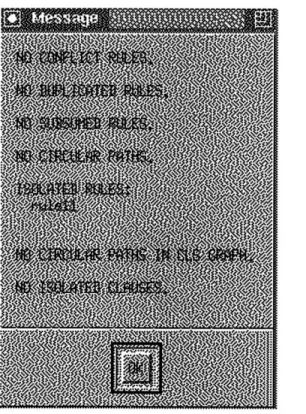
The thirty six rules in the rule base were converted to IF-THEN statement rules, and then tested using the automated verification tool. The verification tool concluded that there are no conflicting rules, no duplicated rules, no subsumed rules, and no circular paths. It detected four isolated rules: rule03, rule 11, rule46, and rule47. As for clauses, there are no circular paths in the clause graph and no isolated rules.
Figure 4.1: Pop up message window displaying verification result for Insurance Plan
The graphical analyzer visually displays the inference relationships among the rules. The problem-free rules are represented by blue color nodes. The inefficient or unnecessary rules (such as redundant rules, isolated rules, duplicated rules) are represented by yellow
.. ... ... .. ... .. ... ... ... ... ... --- ... ... -- ... --- ... --- --- --- --- --- --- --- --- -- ----- --- ---- --- -- --- ---- -- --- -- --- --- --- --- --- -- --:Fie.Grah:iw .
r ·
···.
~ ~'~.:·...
···:·..
~···II·'
Ull 1~ rurIelT ·; ·::::ii
?·. .. ··. ··· i~·· ' ·"""- ··~... ···· ···.. "" ····. ···" ~0' ··· ( `·;:: '`'' ' '~''''· · " '''·· "' · ··· · ''' '' ''''· ·'' "' ' 21: ··::·:: ··. :..' '··::':.:.:·: ·~: ··.: f -::'··'·;:: '' '' ' I~ .... ... *ruel :' ::... il. 'rurol3. ". "
.:...:...
...
.:.:.!·:;~-':2
2·;E:N::
!·ii.j:e.!!~ii0l.~y~::::::.
::::::::::::i::ru,~r~S~:...::. :.!-i:.:.:.. ...
~if ': :· :·.- .~..:. ' "
" "
."."...
..
.
u
ul"l'"4"
:":::
":"..
. " .. .. . ...
/ com tents*/_.I: IHI-
{Curr..nt
..Cteg~r.. frn.
u - 6 * .MONY .M
.: MARKET)thly
.d --. . . . .ry-
. . .. ••. . ..
_ __...I..Figure 4.2: Graphical Analyzer for the rule base of the Insurance Plan Advisor. I I ' ''' " ~' '' "''' ··.-.: ····( ··· .;... ···. '··· ··'···.: '·..~· ····:: '.:: ''·.~·.' '·· I ··. ~. ~· '· '·. :..· ·.: ". ·. ''· ··.:···'.. ~I
colored nodes. The critical rules that result in problems (such as circular chaining and con-flict rules) are represented by red colored nodes. The currently selected node is colored in green.
A user can perform a significant amount of analysis just by looking at the graphical analyzer. For example, the user can analyze the Insurance Plan Advisor expert system by looking at Figure 4.1. The goal of this rule-based system is to determine CategoryOfFund to invest in, given some initial facts. The value instantiated to this variable is the only one a user is interested in. Therefore, any rule or clause that does not directly or indirectly lead to assigning value to this variable is redundant. They should be eliminated to keep the size of rule base minimal. Among the isolated rules which are highlighted in yellow, rule03 draws the conclusion (BasicInsuranceCoverage = ADEQUATE), which is a dangling leaf node. Therefore, rule03 can be deleted from the rule base without affecting the behavior of the system. Similarly, rule47 and rule46 draw the dangling conclusion (ChildrenHeaded-ForCollege = FALSE). These two rules are also deleted from the rule base without altering the system behavior. In addition, notice that rule34 is the intermediate node from rule23 to rule 18. It can be eliminated by the direct inference of rule 18 to rule23.
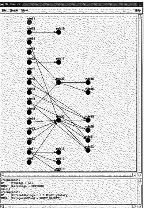
These changes were incorporated to the Insurance Plan Advisor system. Verification was again performed on the modified rule base of Insurance Plan Advisor system. The result shows significant improvements.
Nwfll ~?---IfrC4 4, VE I C0 'M- EU-N 1"L ZN- N'N M Xi ,r•'-t{4,AI I7.,. •t A
r4
ge MXl3Figure 4.3: Pop up message window displaying the verification result of the modified Insurance Plan Advisor system.
The modified rule base contains no error (see Figure 4.3). The only highlighted node on the analyzer graph is rule 11, an isolated node. Though rule 1 is an isolated node, its conclusion clause is assigning a value to the variable CategoryOfFund. Therefore, it is a relevant rule to the system and should not be modified.
f 4 Yxt .SIMON
N ... . .. . .. ... ... .... . . I 7 (TbutYg> ,• '- '.(L' f~,~i ~ ~ .;-: 5 "' · }....;."'...- .:... .. ". :.: " '..) .... : " '.""- '".'::::" " :'"I " "
i• •.•.• 6:: ?.*: '- :. . :-.;.:. :.:i... . -..":.;- ... ::';---:: : .. ::. i.;::.
L'-.
JIV- ft~o.. Odrr·t kv!nj*- x-.iti6 iyd IONE
I·
C/
Figure 4.4: Graphical Analyzer for the rule base of the modified Insurance Plan Advisor system.
4.3 FDIR Boresight
FDIR boresight is a rule-based system for anomaly detection during the boresight pro-cess of the Deep Space Network. It was developed at the Jet Propulsion Laboratory in the
40 ''· ·· ·· · · · ~'.'··~·. '''-·.·-···. · · 2··5·.···5···· · ·· · ·· · · ·· ·· · · 5···2····55 · ·· ·· ·· · · ·-· · ·· · · 2·· · · "' · 5 5 · ·~··~~··· ··~· · · · ·· · ·· ·· ·· · ··· · · 51·,:··~:· ··.::··_·-.::··_···.::··~: · ··.::··~:···,::::·.:::'::·· ''' ··· ·C···· ··· ··· 5· -·~· · · · ·· ·· · · · ·· · · ·~·~···· ·- · ·--· · · · ·· · ·-· ···~ " 2· ··· '·· ·-. ·'· -···'·'.'_···. ~·· ·. ·~ · ~ ·i· ·· ···'· '·..' '···'J '· ~·.··. · ''··.. 1. . ·'··. · · · ·.. .. '·· · ' '· '- - '· ·- ' ' -'-"·"·- ··:'·,_'.::~·.·.:"· ' "~- ''· · '·- '~ -·'''' ' `· ''' ''··'-' ·'''''·''· ~· ''- '· ·-~· '`· "·~· ·· · '··..I···. ~ "''' ·:::'. · ·.'· ''.'. '·· ~·· ~·~.I.:~·,..~'· '·· ···. '" ··· '' ·· '··... ·. · ·'. ; '··~' · ·~ · ·. _·.' · ·..'.''·; '' ;1 ~.. ''. '' " · ''' ''' ''' " '' "·· "' "· ''"' '' '' ''· '" '"' "· ''~ ' ·..'·.·· ·. "..[·_'·-':··."~:·_ '-. "·.: "~·. ·.:: '~-.'.('·: ·· :'·. ''' ' "~··". ·. "·;·'·;·:. _·' · '·: ". ·1'··. `. ''· '·.': ·. ·.- 2. · · ·-·.-~i:r- - . -- · ·- 5 ·· ··· ·. · · · ·· · · ·· ··· ··· ··. "'' ~' "' "' ''· "' '" '' '' z ·· ·'~··.[. .:'. '· ~··~··I· · ··.''· '' · ·· ''" ''' '' "' -··· ·· ·- ?a: "' '~· "'
''~
'~
"'''
'' " ""''
'· ''' "'"''"''~~. ~i.- ' '"~
''
'''
··
"~~·
5.
-..
···..
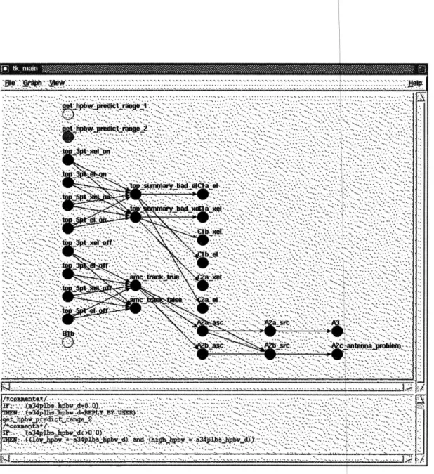
~·..;l-lr- -'G· · ·\~' . ·. ·. ~·. .. 5 ··· · ·· ···· ···· ··· ··· · · · "'- ' ' " ' · · i··:·.'··. '~'' '''' ''"''" "' '' " ''' '''.'."" "'. ~ ~' ''''.' '''"''''''' ''"' .- · · · · .·· .I:.···:··- .;· · ·-. · ~·.):::' ''' :: ... , ·- · ·.'·:.:'··.~'~ · '.···~:: "'" ''"' '" "" -- ··· ·''~·· · ~~····'·'~· "~ '~'····'"~·~ "' ' ' '"' "' '"' ·. .. .. `..''.'' .. , · · ·· . ·· j··~· · · · ·· · · · - ·· · · · ·· · · .:.I. · ··. ·-, '' ~'' 5·~ '" ···5 i:: ___ __________ __·_~i I· _ I "' '" '""''''''' ~ "' "',... -. -.. -. ... '"' ·,.''"' ''~ '' "" "' " · ·····'~ ···· ··~ ':~·· · "''' '''''' ·· ······· ''····'-'' ·· ··· 5·· · · ·. · · · · ·. ·· · · · ·· ~ ··. ·. · · · ·· · ·· · ·· ''·· ·nYe31· · ·. t.2'. · · ·.. -. '·''· ··.: '' '· ·· ··''' · '···· ''· '·· ''' "'" "·5· '··· · ·.. '' ''·· ' · ·- ·· '~ "'· '·'··· '··.. · ·.. .. ~..·~·· :i··· "" '''· '"' '·~ '···...,,....~.· · · · : · · ·:. · · ·~. '" " '· '" ''····~''· '"' "·' "'· ·'''· '''·'·'···"·· ·· .. : ·- · M·. · · ·- ·. ···· · ·- · .... · ···· · . · · · · ·~., . ·."'.'.. ···· ·- "'' .. ~. .,..~ · ···.·. ~··.. -··:~... ·· · · · ·.. · · · · · · · ··- · ··- · · · · · · ·· ·- · ·· · · · ··- · ·· · · · ·.. · ·~ ... -.. .·.:.·: ·· · ~ ·. ·· ... ·.... ...~~ . : . ·· -· · ·· · ·· · · ··· · · ·-'''' ''' '" "' ""' ·. , · ·~ '.'·,.·'··· ·· ·. ;··.1': :~'--.~:·-.'··.:~: '" ·· ·· ·· ·· ·· ·· · · · · · · · · ·· · · · · · · · · · · · · · · · · · · · · · · -___~_~__~~~~~_~_~_~~~__~_~__~~ c~~u ---- · · -- ·- -- · ·-lliilCllii~*il*;li~*l*iC·*·l*i*···-· · · ··· ·· · ~···-· ~···-·~···-· ··· ~··~ ·· · · · · · · ·· · · · ··· ·· · ··· · · · · -~·· · · · · · · ·· · · · -······ · ··-· ·· · · · · ····~ ···~· ···. ·5 ·· ··· '·''· ~~·· '~' · · ·'··'··I.··. · ·.: ·. · ·... ·5.. . ·· · ·· ~· ~.. . · · i··. ·.'·. · · ·. .. ·1·-:·'·.: "·· · ·"'···.. · · ·.:"·i··' · · ·-'· ·,· '~'' ''''' '''' ' ""'''''' ~"''''~ · · r...:: ·.. .,~·.'·.: ~·· ~··· · .··~· ·· ·· ,:~" "'' "·~'· ''''· ·-, ·~···. · · · ·'· :·.· · · ·. ... .. " . · ''·"'~· I.:'··," -··-. ""--·.· ··: ·. ·. · ·...·· :··.. · · ·-.... ·· ·- · ·· ~···~~`·:··''· ''.·:'..-;.'1·.·.~~·~5~: "'- 'b~· .·· · '.·· ~·. ·.. :-; ·. ~·'··.. I ---- ·--- ·-- ·- ·--- ·-·- ---- ·-·--- ·--- ·--- ·---·-·-·----expert system shell language CLIPS. The rule base of FDIR was translated into simple IF-THEN statement rules so that it is in the syntax of the automated verification tool. Some rules cannot be directly translated and thus need to be modified. For example, for all the rules that prompt user for variables' initial values, a typical initial value was assigned to each. The rules that simply convert input data into desired format, specifically from inte-ger to float, are ignored. The original rule base written in CLIPS has thirty two rules. The equivalent rule base in the automated verification tool has twenty seven rules.
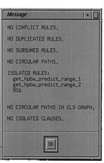
FDIR Boresight rule base has no conflict rules, no duplicated rules, no subsumed rules, and no circular paths. It merely has three isolated rules: get_hp wpredict_range_1, get_hpbwpredict_range_2, and B lb. ý!n FA !*., ·· · · ·· ... ·...5··· · · · C··· · · · rr···5··· · · ·.· · · ~··· · · · I··· · · · · · ·. ~~~~~.··...~~· · · · · 5··· · ~-··~~~··· · · · ~~~~.···.-· · · · ~·5~~~.·~··5···· · · · · ·· · · · ·· · · 5···.· · ·5· · ··· · · ·- C··~···~~~ ~.~~···. · · · 5 · · ·- ~p~··~·. ·· -·· · ·· · · ·· -·· · · ·- · · · ·..-.·. .·....·· ·... i·. ·. ·. · · ···~.. ·.. · · ·.. · · ·~.. ·. · ~...~ .,... ··.. · .. ·-. · ... ·...-. ... , · ·. ~. .·.~... ··~.. ,~~~~ , ·. ·... ··. · ··. ·... ·... · · ·· ·.. ,. ··.·~ ·· ..-. ·.·· · ... 5 ., .,~·... ·· .. · ·.. · · ··.. r~3~w~~ieaidf~~arg~·· ·.. '''" .~.~ -"' "'· ' ' - ·... '"' ·. ··.. ''' ... .... ~ ~... " ' ~... ... , ''' ''" '''''' '' '- '''-··''· "· ·· '·· ' ' · ··.... '"' · ·~ .. " ' · ·... " ' " ' · · "·· '' ' '"' · · · '· '" "' ""· "'' "· '' .... ,.·· '"" ·· · · ·''" ''·'· '- '-5: ··· · .,~ · ·· '·· ·· ·'·· '' '''' ·· ·z ·' '-···'"'··· · · '''-''··'' '''' · · '' '"··· "' ·-- · · ·· · · -'·· ' · ·· ·· ''·· ··· "'····~'···"'''· · ·''·"' ·· · · ·· ''''''"' ·· ''· "' '" '"' -··· ·.. '" · ·· ··-· '"·· · ·· ... ,. · · · ·" · · "- '-·· "' '· ''· -`''''''''' '· "' ... :. '"' '''`''''·· · '''' z''' ~· ·.. .. ~ ·. ·, '' · ·. ·.. ... ~ ' '' ' ' ''' .... '"'· ·· .· ·... . ·.. ... .····.·· ·· · · .·.. .. ... ·~. .. · .·... .~ ·.. ·. ~. .. ·...-... ... " '"~ ·· · · .~,· .. · · ·· * .. . ... *'** .. * ... > · · · '''· . . .' · . '·.. . .. ·.~. .r. l . . ... ... . . . . .... ~.· ... ... .. .. .... .. j/ cg l~ezta t .*f · .. .. ,··· .. -;··. ·.... ·· · · ·· IXY'' hd.' "3ph &·P'h W"L Y "y .·· ... c · ' ·. .- ,'.·" · · · · Z` '.~~ ' " .5 l/*i s~~b:onRt~·n'· *t -~~~~· (a4"b b3(oo -~" __ __ __ __ __ _
Figure 4.6: Graph analyzer for the rule base of FDIR Boresig t system.
The automatic graph layout algorithm works well for Boresight le-based system. The inference relationships are clear and edge-crossings are minimal.
42 i I
jn
_ _li_ ~___~__~~~~~~~~__~~~~._~______~_~_~_~~~~F.T0,
--- --- --- -- ---···. ·· ·- · · · · · · · ··.. ' ''' ''' '''' '''~ ""''' ''"·' ''· '' ''' '' ''"~'5''''' ~' "'" '' ''' "'''' "' ' 2' ' ' "' ''' '''"'' ·" · '' ' ' '- '' ""' '' ~' '' '' ~~' · '~~''''''' '" '"' '" ·,. -. ...··. · ·. · ·. · ·... . · · · ·. · · -.. ··. , · ·. ·- ··... .· ··. · ··. ··. ·· · ·· · · """ · · ·. ·.. · · · · · -.. ·.. · ·. ··.. · ··.. · ·· · · ·.. · · ·-. · · .. · · · .···.·· · ·· · · · ·. · ·. · · · · ·.. " '' ' "'' "' ''' "'' · ' ·· · ·. · ·- · · · ·- ~, · ·= .·~..--· .·~..--·.·~..--· .·~..--· .·~..--·.·~..--·.·~..--· .·~..--· .·~..--· .·~..--· -.·~..--·.·~..--· ·... -· ·. I··~···.:·· · · · · ·· · · · ·. -,· · · · · · ·· · · ·· · -- · · · ·· · .. .. · ·. .·... · ·.. ..-... · . · ·· · ~. -· ·· · · · · ·· · · · · ·· · · · ·- · ·· · ··· · · · · · · · ·· · ·· · ··· · · · · · ·. -·:·~. ·. ·.. · ·- · -····-. · · · · ·· · · · · · ·· "·· · ~·· ··~::'·::'···~'···_; ~··- -· · ·· ~·· ~··· ·.. ··· · · ~· · ~2- ~-··· ·5 · · 5· · 5 · · · · ·· · · · · ·· · · ·~ '-· "''Chapter
5
Conclusion
5.1 Successes
The automated verification tool for rule-based expert systems has a lot of potential. The graphical analyzer simplifies the task of verification for expert systems. It is useful for both non-programmers who know little of verification process and software engineers who are experience programmers. The visual analyzer clearly shows the inference interac-tion among the rules. All problem rules are represented by highlighted nodes. It is extremely helpful for examining the rules. The user can effortlessly trace through the inference paths by following the directed edges through the graph.
Implementing a meta-language front-end to the tool has many benefits. Since the rules are entered in simple IF-THEN statements, users need not learn any expert system shell language, the traditional front-end development environment. Also, verification is done in the meta-knowledge, independent of any expert system shell language. This tool can eas-ily be adopted to work with any shell language, and therefore, is applicable to many rule-based systems developed in various shell languages.
5.2 Failures
The automated graph layout algorithm is inefficient. The analysis graphs for the sample rule-based systems contained a substantial amount of edge-crossing. As the amount of nodes increased, especially in the example of clause graphs where each node represented a clause, the analyzer graph became impractical. When there are large amount of nodes in a graph, the fixed screen size constraints to view only part of an analyzer. For a large rule
base, it is possible that two adjacent nodes with a connecting edge linking them together cannot be viewed in the same visible window. If this research is continued in the future, a better algorithm should be implemented instead.
Chapter 6
Future Work
6.1 Feature Improvements
All modules and features in this automated verification tool were developed
specifi-cally for this project. No existing customized modules or other commercially available components were used. Due to time constraint, the application neglected several funda-mental issues in application development such as ease of use, user-friendliness, and easy to follow instructions, which are critical for real applications. The graphical user interface is an attempt to make the application easy to use, but the operation features are still primi-tive. Improvements and additional features for the graphical user interface are needed to make the tool more user-friendly. Though a user-friendly graphical interface is not critical to the performance of the verification tool, it is an essential component to a successful package of verification tool.
Much more work is needed in searching for a better automatic graph layout algorithm. The visual analyzer displaying inference relationship among rules in a rule base and high-lighting rules of potential problems is the prominent function of this verification tool. The analyzer is useless without a good graph layout algorithm to display the relations among the rules clearly. Thus, a successful automatic graph layout program is critical.
More features can be implemented in the graphical analyzer to aid in analysis of a rule base. For example, one feature could be highlighting the inference path a rule base traces through for a given set of initial facts. This will enable users not only to verify for rule base correctness, checking to see if rules are inferenced correctly, but also to validate the knowledge base, making sure the behavior of the system is what the experts intended.