HAL Id: hal-01245678
https://hal.archives-ouvertes.fr/hal-01245678
Submitted on 19 Dec 2015
HAL is a multi-disciplinary open access
archive for the deposit and dissemination of
sci-entific research documents, whether they are
pub-lished or not. The documents may come from
teaching and research institutions in France or
abroad, or from public or private research centers.
L’archive ouverte pluridisciplinaire HAL, est
destinée au dépôt et à la diffusion de documents
scientifiques de niveau recherche, publiés ou non,
émanant des établissements d’enseignement et de
recherche français ou étrangers, des laboratoires
publics ou privés.
Kévin Berger, Bashar Gony, Bruno Douine, Jean Lévêque
To cite this version:
Kévin Berger, Bashar Gony, Bruno Douine, Jean Lévêque. Magnetization and Demagnetization
Stud-ies of a HTS Bulk in an Iron Core. IEEE Transactions on Applied Superconductivity, Institute of
Electrical and Electronics Engineers, 2016, 26 (4), pp.4700207. �10.1109/TASC.2016.2517628�.
�hal-01245678�
Magnetization and Demagnetization
Studies of a HTS Bulk in an Iron Core
Kévin Berger, Bashar Gony, Bruno Douine, and Jean Lévêque
Abstract—High Temperature Superconductors (HTS) are
promising materials in variety of practical applications due to their ability to act as powerful permanent magnets. Thus, in this paper, we have studied the influence of some pulsed and pulsating magnetic fields applied to a magnetized HTS bulk sample. The bulk sample, the iron core, the two inductors and the current sources used to magnetize and demagnetize the superconducting bulk in the iron core are presented. Then, we detail various magnetizing and demagnetizing processes, and their purposes. For the magnetization studies, we have shown that there is no significant difference between the Successive Process and the Direct Process of magnetization. The maximum Trapped Magnetic Field (TMF) is about 1 T, 10 min after the magnetization process. For the demagnetization studies, we propose many results as a hysteresis loop corresponding to the pulsed demagnetizing field influence. Various time evolutions of the TMF are also shown: when the demagnetizing AC field is applied a few minutes after or several days after the magnetization. This leads to completely different results, from 5 % / min to 1 % / (6 hours) of reduction of the TMF. The results presented here, give many practical information to users of superconducting bulk magnets. We assume that decreasing the temperature will increase the capabilities of trapping the magnetic field. We conclude that a strong interest must be kept on the applications of HTS bulks in Electrical Engineering, preferably at lower temperature than 77 K.
Index Terms—Demagnetization, flux creep, high-temperature
superconductors, hysteresis loop, magnetic cores, magnetic relaxation, magnetization, trapped-field magnets.
I. INTRODUCTION
IGH Temperature Superconductors (HTS) are promising materials in variety of practical applications. Due to their ability to trap record magnetic fields, they can act as powerful permanent magnets. The record trapped magnetic flux density, of 17.6 T in a bulk (RE)Ba2Cu3O7, is much higher than the saturation magnetization of conventional NdFeB magnets [1], [2]. This physical properties of trapping and shielding magnetic fields make them extremely promising for various applications such as magnetic bearings [3], [4], and high power density rotating machines [5]–[10].
Despite the difficulties related to (RE)BaCuO bulks, in terms of manufacturing large single-domain bulk and/or in
This work was supported in part by the French National Research Agency under Grant ANR-14-ASTR-0009 called RESUM for REalisation of a SUperconducting Motor.
Corresponding author: K. Berger (e-mail: [email protected]). K. Berger, B. Gony, B. Douine and J. Lévêque are with the University of Lorraine, GREEN, Research Group in Electrical engineering and Electronics of Nancy - EA 4366, Faculté des Sciences et Technologies, BP 70239, 54506 Vandoeuvre-lès-Nancy Cedex, France (e-mail: [email protected]).
large quantity, with good and homogeneous properties, they are still the most promising materials for the applications of superconductors.
There are several ways to magnetize HTS bulks; but we assume that the most convenient one is to realize a method in situ, i.e. a Pulsed Field Magnetization (PFM). We have studied in previous works, the PFM process [11] and the influence of an iron core on the Trapped Magnetic Field (TMF) in [12].
Since superconducting magnets are already used in some prototypes of HTS synchronous machine as in [13], we believe that it is necessary to increase our knowledge on the magnetization and demagnetization behavior of the HTS bulks acting as permanent magnets. To the best of our knowledge, no such experimental analysis were proposed in the scientific literature.
In this study, we will apply some pulsed and pulsating magnetic fields to a magnetized HTS bulk sample. These fields will be also called demagnetizing fields since they tend to decrease the TMF of the sample. Section II is devoted to the presentation of the equipment used in the experiments. Then, we present various magnetizing and demagnetizing processes and their purposes. Finally, several results of the magnetization and demagnetization studies are shown, with an emphasis on providing a maximum of practical information.
II. EXPERIMENTAL EQUIPMENT
In this section, the superconducting bulk, the iron core, the two inductors and the current sources used to magnetize and demagnetize the superconducting bulk in the iron core are presented. In this work, the experiments were performed only at the temperature of liquid nitrogen 77 K.
A. Superconducting bulk sample and sensors
The superconducting bulk used in all the measurements is a (RE)BaCuO type pellet from ATZ. Its dimensions are 31 mm for the diameter, and 16 mm of height. The critical temperature of this material is around 92 K. The sample was able to trap 0.95 T by using a Field Cooling (FC) process at 77 K with a sweep rate of 0.15 T / min.
The measurements of the Trapped Magnetic Field (TMF) on the bulk were taken using two high linearity Hall sensors HHP-NP from AREPOC. The first one at the center of the top surface (seed location), and the second at a radius of 1 cm on the same surface. These sensors will be later called “center” and “r = 1 cm” respectively. The distance between the active part of the sensors and the surface of the bulk is about 0.5 mm. Unless otherwise stated, the values of the trapped magnetic field are recorded about 10 min after the end of the current pulse.
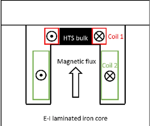
Fig. 1 shows the structure of the “E-I” laminated iron core which contains 200 insulated sheets of grain-oriented electrical steel (FeSi 3 wt%) of 0.35 mm thickness. The HTS bulk sample is place above the central leg of the iron core that we had previously cut. In the experimental configuration, an air gap of 6 mm is confined between the HTS bulk and the “I-shaped” part of the iron core. The entire core measures 130 mm high, 150 mm width and 73 mm deep.
C. Coils generating the applied field
A set of two copper coils were used to magnetize and demagnetize the HTS bulk. A round coil around the bulk as in [12] and a rectangular coil around the central leg of the iron core.
The round coil, of 17 turns, is resin impregnated and there is a textile tape around the coil to perfectly match with the bulk size. Thus, the heat coming from the coil is not directly transmitted to the HTS bulk. The second coil, of 42 turns, was added in order to increase the total number of Ampere-turns of the system, and to allow us to apply an AC magnetic field about 120 mT to the sample, without worrying about the limitations of our power supply. These 2 coils are connected in series so that the total number of turns is 59.
The picture in Fig. 2 presents the entire system used in the experiments. As we can notice, the HTS bulk, the Hall probes and the 2 coils are placed, while the “I-shaped” part of the magnetic circuit has to be placed later on the top.
To give an order of magnitude to the applied magnetic field Bapp to which the HTS bulk is submitted, we have measured
the values of the magnetic field, within the iron core at 77 K, at a location equivalent to the center of the top surface of the HTS bulk, but without it, Fig. 3.
D. Current sources to supply the coils
For the Pulsed Field Magnetization, we used the same system describe in [12]. It is a bank of 24 capacitors with a total capacity of 80 mF. The capacitor voltage is up to 300 V while the set of capacitors can withstand 50 kA. The discharge current is initiated by triggering of a thyristor that has a maximum current of 15 kA.
using a bipolar power supply of 1 000 W made by KEPCO, a BOP 20-50MG. This latter can provide maximum values of current and voltage of ±50 A and ±20 V, with sinusoidal wave frequency up to 443 Hz.
III. MAGNETIZATION AND DEMAGNETIZATION PROCESSES
A. Magnetization process
With the system describe above, we have tested and compared two processes of magnetization:
1. The Successive Process (SP):
The HTS bulk is always kept in the liquid nitrogen. We first apply an initial magnetic pulse to the sample, as a consequence, a magnetic field Btrap is trapped. Since the HTS
is still at 77 K, The trapped magnetic field in the sample is maintained. Then, we increase the amplitude of the magnetic field, by increasing the initial voltage of the capacitors VDC,
until we reach the maximum of trapped magnetic field. This pulse is later referred to as the optimal pulse.
2. The Direct Process (DP):
In this process, we first apply an initial magnetic pulse to the sample, as a consequence, a magnetic field Btrap is trapped.
Fig. 2. Picture of the magnetic core. The HTS bulk, the Hall probes and the 2 coils are placed. The “I-shaped” part of the magnetic circuit has to be placed on the top.
Fig. 3. Applied magnetic field plotted vs. the number of Ampere-turns. The values are measured at 77 K within the iron core, at a location equivalent to the center of the top surface of the HTS bulk, but without it.
Fig. 1. Illustration of the “E-I” laminated iron core with the HTS bulk in place and the 2 coils used to apply the magnetic field.
Then, we heat the HTS bulk, and as a results, its trapped magnetic field vanishes. The sample is again cooled down to 77 K, and the amplitude of the applied magnetic field is increased. The pulse that produces the maximum of trapped magnetic field is the optimal pulse.
B. Demagnetization process
In order to realize a synchronous motor with superconducting magnets, for instance, it is essential to study the influence of a demagnetizing field on the trapped magnetic field in the HTS bulks. It is not obvious to assess the kinds of waves, and their amplitudes to which the HTS bulk will be exposed in a real motor. Anyway, the calculation of eddy current losses in Permanent Magnets (PM) is not a solved problem, and most of the time a Finite Element Method (FEM) software is required. This demagnetization field that may come from the stator windings, is a pulsed magnetic field or a pulsating magnetic field.
When a short circuit occurs in a motor, or when a charge change suddenly, the current in the armature can produce a pulsed magnetic field that tends to demagnetize the superconducting magnets or PM. The effects of this kind of demagnetizing field will be also shown in Section V.A.
Concerning the pulsating magnetic field: the spatial angle between the axis of the superconducting bulk, or permanent magnet, and the magnetic field produced by the armature, is not fixed and depends on the load conditions of the motor. In our case, since we use a fixed magnetic core it is not possible to realize such angular variation. The amplitude of the pulsating magnetic field is not well known, but a maximum range of 100 to 200 mT seems reasonable in a classical windings configuration. Since the magnet turns at the same speed as that as of the armature field, and due to the three-phase system, the harmonics 5 and 7, 11 and 13, 17 and 19, etc. are the only operating harmonics.
In the experiments of demagnetization, shown in Section V.B, the HTS magnet in the iron core will be exposed to a sinusoidal magnetic field with 120 mT as a maximal amplitude and with several frequencies. This value of 120 mT was measured, for a given value of current, with the Hall probe located at the center of the HTS bulk surface and at room temperature. That is to say that this value can be considered as the demagnetizing field directly applied on the sample surface.
IV. RESULTS OF THE MAGNETIZATION STUDIES
Fig. 4 shows the comparison of the two magnetization processes (SP and DP) in terms of trapped magnetic field measured at the center and at r = 1 cm on the top surface of the HTS bulk. At low VDC, the HTS bulk is not fully
magnetized and it is normal that the TMF is higher near the edge than the center. The optimal values of TMF at the center are obtained for VDC = 160 V for the Direct Process instead of
220 V for the Successive Process. These values of VDC can be
used to define the optimal pulses. For the two processes we can almost find the same maximum value of TMF about 0.9 T. By repeating the optimal pulse 3 times, we can enhance by
10 % the TMF of each process (filled symbols in Fig. 4). The number of repetitions of the pulses of 3 is not arbitrary, but leads to the best results in practice.
V. RESULTS OF THE DEMAGNETIZATION STUDIES
A. Pulsed demagnetizing field
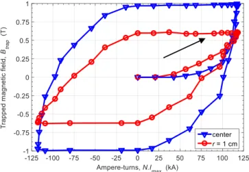
The successive process is used in order to achieve the full hysteresis loop corresponding to our sample. We should mention that this loop, shown in Fig. 5, has a completely different meaning than those for PM. In fact, each point of the loop corresponds to a pulsed magnetization experiment. The maximum current is then recorded and the total number of Ampere-turns is used for the x-axis. Fig. 5 provides very important information for studying the pulsed demagnetizing field that may occurred in superconducting motors. Fig. 5 can also be used for shaping the flux profile at the sample surface. In fact, when the 2 loops cross each other, it means that the TMF is the same at the center and at r = 1 cm, and this leads to a flat profile of magnetic field on the top surface of the sample.
Fig. 5. Hysteresis loops corresponding to the TMF at the center and at
r = 1 cm on the top surface of a HTS bulk, plotted vs. the number of Ampere-turns measured during the experiment. Each point of the loop corresponds to a pulsed magnetization experiment.
Fig. 4. Comparison of the two magnetization processes (SP and DP) in terms of TMF measured at the center and at r = 1 cm on the top surface of the HTS bulk. The x-axis corresponds to the initial voltage VDC of the capacitors
because it was our control variable. The filled symbols correspond to an enhanced value of TMF obtained by applying 3 times the optimal pulse.
B. Alternative demagnetizing field
There are several ways to apply the demagnetizing field on
the AC demagnetizing field:
1. A few minutes after the magnetization process, when the flux creep is significant, i.e. the electrical field is high in the superconductor, will be referred to as “High Creep State” (HCS).
2. Several days after the magnetization process when the flux creep is less significant, i.e. the electrical field is negligible in the superconductor, will be later called “Low Creep State” (LCS).
On this basis, the AC demagnetizing experiments have occurred during almost 3 months.
1) High Creep State
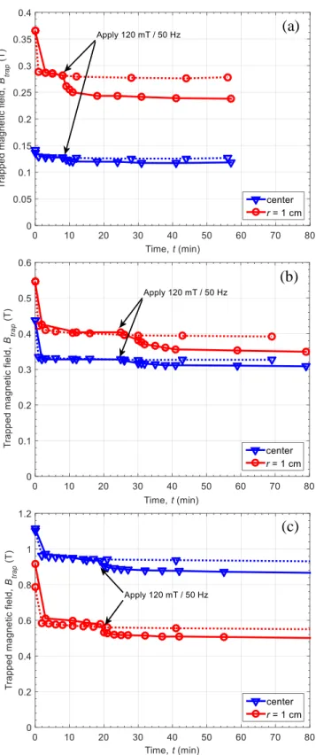
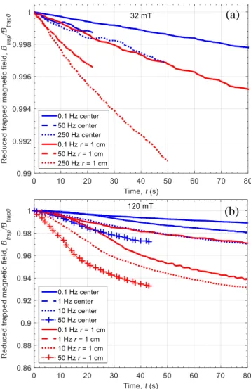
Fig. 6 shows the influence of an AC demagnetizing field of 120 mT at 50 Hz applied 10 to 20 min after the magnetization of the HTS bulk. Dotted lines correspond to the TMF evolution without any AC demagnetizing field. In Fig. 6(a), for a low TMF in the center, and since the magnetic field penetrates from the edge to the center, the influence of the AC demagnetizing field is more significant on the magnetic field located at r = 1 cm than at the center, 15 % and 7 % of decrease respectively. In Fig. 6(b), for a flat profile of TMF on the bulk surface, and since the magnetic field penetrates from the edge to the center, the relative decrease of TMF are of 12 % at r = 1 cm and 5 % at the center. Finally, in Fig. 6(c), for the highest TMF obtained, the relative decrease are of 17 % at r = 1 cm and 11 % at the center. As a conclusion, the relative decrease of TMF is always higher at r = 1 cm than at the center. We can also observed that the absolute value of the decrease of the TMF is always lower than the AC field amplitude. In the worst case, this value is half the value of the AC field amplitude, that is, 60 mT for 120 mT of applied field. Fig. 7 shows the time evolution of the reduced TMF when AC magnetic fields with several frequencies are applied on the HTS in the High Creep State. The reduced TMF is the ratio Btrap / Btrap0 with Btrap0 stands for the TMF before applying the
demagnetizing field. At the beginning of the demagnetization process, we can see on Fig. 7(a), for an AC amplitude of 32 mT, and for the worst case scenario, that is at 250 Hz, the relative decrease of TMF is about 1 % for 60 s. For an amplitude of 120 mT, in Fig. 7(b) this relative decrease is about 7 % for 60 s at 50 Hz.
The relative decreases of the TMF in the HCS are around a few percentage per minute. Although it represents a high rate of variation, this relative decrease is assumed to follow a logarithmic time evolution as:
1 ln ln 1 and 1 trap trap B t m m B n (1)
with m the slope of the reduced TMF plotted in a linear scale, n the exponent of the typical power law used for modeling HTS, and is a time constant which determines a transient stage before the beginning of the logarithmic relaxation [14], [15].
Fig. 6. Influence of an AC demagnetizing field of 120 mT at 50 Hz applied 10 to 20 min after the magnetization of the HTS bulk, i.e. in the High Creep State. Dotted lines correspond to the TMF evolution without any AC demagnetizing field. (a) For a low initial TMF obtained with the Direct Process and VDC = 100 V. (b) For a flat profile of TMF obtained with DP and
VDC = 120 V. (c) For the highest TMF obtained with the DP and
VDC = 160 V.
(a)
(b)
In our case, the m value for the flux creep relaxation in (1) has been estimated to 0.0123, i.e. (RE)BaCuO sample of 31 cm of diameter in an iron core cooled at 77 K. This value has been estimated for the 2 last days of the 2 weeks of flux relaxation, and it corresponds to an n-value of 82. This value is high compared to the literature, and the iron core seems to have something to do with this. On one hand, these parameters of flux relaxation will take 4.741013 years before the TMF will be reduced by 50 %. On the other hand, 5 years after the magnetization, the TMF will still be at 72 % of its value just after the magnetization process.
Since the applications of HTS bulk magnets require a long operation time, studying the influence of a demagnetizing field on a long period, such as several days or weeks, is clearly more important, but also time-consuming. This last issue would be the matter of the next section.
2) Low Creep State
Fig. 8 shows the time evolution of the TMF when an AC magnetic field of 120 mT at 50 Hz is applied to the HTS in the Low Creep State, 14 days after the magnetization. This experience lasted for nearly a month. In Zone 2 of Fig. 8, as the AC field is applied, we can observe that the TMF
decreases suddenly, and that the decrease occurs with a negative slope in the linear time scale. This behavior is typically observed when some AC losses occur and increase locally and globally the temperature of the sample. In Zone 3, the flux creep continues but according to the thermal time-constants the system should “stabilize”. If we apply once again the AC field of 120 mT at 50 Hz, see Zone 4, we notice that no abrupt decrease of the TMF is observed and the slope seems to be the same as in Zone 3. As an important conclusion: the influence of AC demagnetizing fields are not cumulative. If an AC demagnetizing field is applied once, then an AC field with equivalent or lower amplitudes will be without effect. Unfortunately, we do not have more data available at this point.
We have conducted the same kind of experiment by applying an AC magnetic field of 32 mT with 50 Hz during 7 days and 5 days after the magnetization process, Fig. 9. Similarly to the case experiment with an amplitude of 120 mT, an abrupt decrease of the TMF is first observed when the 32 mT / 50 Hz demagnetizing field is applied. After that, the flux relaxation that occurred during the first 5 days seems to
Fig. 8. Time evolution of the TMF when an AC magnetic field of 120 mT at 50 Hz is applied on the HTS in the LCS, 14 days after its magnetization. Fig. 7. Time evolution of the reduced TMF when AC magnetic fields with
several frequencies are applied on the HTS in the HCS, a few minutes after the magnetization process. (a) 32 mT of amplitude at {0.1, 50, 250} Hz. (b) 120 mT of amplitude at {0.1, 1, 10, 50} Hz.
(a)
(b)
Fig. 9. Time evolution of the TMF when an AC magnetic field of 32 mT at 50 Hz is applied on the HTS in the LCS, 5 days after its magnetization. The frequency is then increased to 250 Hz, and after what, decreased to 10 Hz and 0.1 Hz without significant change.
the TMF during the 7 days with demagnetizing field of 32 mT / 50 Hz.
An increase of the frequency of the AC field is then made, and surprisingly, no change of the slope of the decay of the TMF is observed during one day. The frequency is then decreased, first to 10 Hz, and then to 0.1 Hz producing the same results, i.e. no change observed.
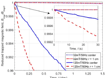
Concerning the time evolution of the reduced TMF in the Low Creep State, we have also made several experiments. Fig. 10 shows the time evolution of the reduced TMF when AC magnetic fields at 50 Hz, of 32 mT and 120 mT of amplitude are applied on the HTS in the LCS, several days after the magnetization process. For an AC amplitude of 32 mT, the relative decrease of the TMF is completely invisible on this figure. For the amplitude of 120 mT, the relative decrease of the TMF at the center is lower than 0.5 % for ¼ day (6 hours), and lower than 1 %, at r = 1 cm, for the same duration. These values and the inset showing a zoom on the first 30 seconds prove that the behavior of the HTS bulk against the
observed in the HCS, in Fig. 7.
Although the decrease of the relative TMF for an AC field of 32 mT at 50 Hz has not been observed in Fig. 10, we can see the presence of decrease in Fig. 11. The slope of this decrease is linked to the frequency of the AC demagnetizing field. As expected, higher is frequency, higher is the decrease of the TMF. However, the order of magnitude is about 0.01% per hour.
VI. CONCLUSION
Through this article, we have deeply investigated the magnetization and demagnetization of (RE)BaCuO bulks. The experiments in relation with the potential applications of HTS bulk have been performed for various pulsed and pulsation demagnetizing fields. The results presented here, give many practical information to users and potentials users of superconducting bulk magnets. All the values are consistent and detailed. The liquid nitrogen temperature was a limiting factor, however we assume that decreasing the temperature will increase the capabilities of trapping the magnetic field. This also leads to less flux creep in the sample. In other words, a strong interest will still need to be devoted to the applications of HTS bulks in Electrical Engineering, preferably at lower temperature than 77 K.
ACKNOWLEDGMENT
The authors would like to thank Isabelle Schwenker for her help during the experiments, and Anis Smara for proofreading the English.
REFERENCES
[1] M. Tomita and M. Murakami, “High-temperature superconductor bulk magnets that can trap magnetic fields of over 17 tesla at 29 K,” Nature, vol. 421, no. 6922, pp. 517–520, Jan. 2003.
[2] J. H. Durrell, A. R. Dennis, J. Jaroszynski, M. D. Ainslie, K. G. B. Palmer, Y.-H. Shi, A. M. Campbell, J. Hull, M Strasik, E. E. Hellstrom, and D. A. Cardwell, “A trapped field of 17.6 T in melt-processed, bulk Gd-Ba-Cu-O reinforced with shrink-fit steel,” Supercond. Sci. Technol., vol. 27, no. 8, p. 082001, 2014.
[3] T. Coombs, A. M. Campbell, R. Storey, and R. Weller, “Superconducting magnetic bearings for energy storage flywheels,”
IEEE Trans. Appl. Supercond., vol. 9, no. 2, pp. 968–971, Jun. 1999.
[4] T. M. Mulcahy, J. R. Hull, K. L. Uherka, R. G. Abboud, and J. J. Juna, “Test results of 2-kWh flywheel using passive PM and HTS bearings,”
IEEE Trans. Appl. Supercond., vol. 11, no. 1, pp. 1729–1732, Mar.
2001.
[5] A. Álvarez, P. Suárez, D. Cáceres, X. Granados, X. Obradors, R. Bosch, E. Cordero, B. Pérez, A. Caballero, and J. A. Blanco, “Superconducting armature for induction motor of axial flux based on YBCO bulks,”
Phys. C Supercond., vol. 372–376, Part 3, pp. 1517–1519, Aug. 2002.
[6] B. Oswald, K.-J. Best, M. Setzer, M. Söll, W. Gawalek, A. Gutt, L. Kovalev, G. Krabbes, L. Fisher, and H. C. Freyhardt, “Reluctance motors with bulk HTS material,” Supercond. Sci. Technol., vol. 18, no. 2, p. S24, 2005.
[7] G. Stumberger, M. T. Aydemir, D. Zarko, and T. A. Lipo, “Design of a linear bulk superconductor magnet synchronous motor for electromagnetic aircraft launch systems,” IEEE Trans. Appl.
Supercond., vol. 14, no. 1, pp. 54–62, Mar. 2004.
[8] E. H. Ailam, D. Netter, J. Leveque, B. Douine, P. J. Masson, and A. Rezzoug, “Design and Testing of a Superconducting Rotating Machine,” IEEE Trans. Appl. Supercond., vol. 17, no. 1, pp. 27–33, Mar. 2007.
Fig. 10. Time evolution of the reduced TMF when AC magnetic fields at 50 Hz, of 32 mT and 120 mT of amplitude are applied on the HTS in the LCS, several days after the magnetization process. The inset shows a zoom on the first 30 seconds.
Fig. 11. Time evolution of the reduced TMF when AC magnetic fields of 32 mT of amplitude at {0.1, 10, 250} Hz are applied on the HTS in the LCS, several days after the magnetization process.
[9] R. Moulin, J. Leveque, L. Durantay, B. Douine, D. Netter, and A. Rezzoug, “Superconducting Multistack Inductor for Synchronous Motors Using the Diamagnetism Property of Bulk Material,” IEEE
Trans. Ind. Electron., vol. 57, no. 1, pp. 146–153, Jan. 2010.
[10] R. Alhasan, T. Lubin, K. Berger, J. Lévêque, and B. Douine, “A new kind of superconducting motor,” in EUCAS 2015 - 12th European
Conference on Applied Superconductivity, Lyon, France, 2015, p. page
62/2M–LS–O1.6.
[11] B. Gony, R. Linares, Q. Lin, K. Berger, B. Douine, and J. Leveque, “Influence of the inductor shape, and the magnetization processes on a trapped magnetic flux in a superconducting bulk,” Phys. C Supercond., vol. 503, pp. 1–6, Aug. 2014.
[12] B. Gony, K. Berger, B. Douine, M. R. Koblischka, and J. Leveque, “Improvement of the Magnetization of a Superconducting Bulk using an Iron Core,” IEEE Trans. Appl. Supercond., vol. 25, no. 3, pp. 1–4, Jun. 2015.
[13] Z. Huang, M. Zhang, W. Wang, and T. A. Coombs, “Trial Test of a Bulk-Type Fully HTS Synchronous Motor,” IEEE Trans. Appl.
Supercond., vol. 24, no. 3, pp. 1–5, Jun. 2014.
[14] A. Gurevich and H. Küpfer, “Time scales of the flux creep in superconductors,” Phys. Rev. B, vol. 48, no. 9, pp. 6477–6487, Sep. 1993.
[15] P. Vanderbemden, Z. Hong, T. A. Coombs, S. Denis, M. Ausloos, J. Schwartz, I. B. Rutel, N. Hari Babu, D. A. Cardwell, and A. M. Campbell, “Behavior of bulk high-temperature superconductors of finite thickness subjected to crossed magnetic fields: Experiment and model,”