Publisher’s version / Version de l'éditeur:
Vous avez des questions? Nous pouvons vous aider. Pour communiquer directement avec un auteur, consultez la
première page de la revue dans laquelle son article a été publié afin de trouver ses coordonnées. Si vous n’arrivez pas à les repérer, communiquez avec nous à PublicationsArchive-ArchivesPublications@nrc-cnrc.gc.ca.
Questions? Contact the NRC Publications Archive team at
PublicationsArchive-ArchivesPublications@nrc-cnrc.gc.ca. If you wish to email the authors directly, please see the first page of the publication for their contact information.
https://publications-cnrc.canada.ca/fra/droits
L’accès à ce site Web et l’utilisation de son contenu sont assujettis aux conditions présentées dans le site LISEZ CES CONDITIONS ATTENTIVEMENT AVANT D’UTILISER CE SITE WEB.
Proceedings of the IEEE International Conference on Mechatronics & Automation,
pp. 144-147, 2005-07-01
READ THESE TERMS AND CONDITIONS CAREFULLY BEFORE USING THIS WEBSITE.
https://nrc-publications.canada.ca/eng/copyright
NRC Publications Archive Record / Notice des Archives des publications du CNRC :
https://nrc-publications.canada.ca/eng/view/object/?id=4168e513-1d6c-4240-8a51-190562450a95 https://publications-cnrc.canada.ca/fra/voir/objet/?id=4168e513-1d6c-4240-8a51-190562450a95
NRC Publications Archive
Archives des publications du CNRC
This publication could be one of several versions: author’s original, accepted manuscript or the publisher’s version. / La version de cette publication peut être l’une des suivantes : la version prépublication de l’auteur, la version acceptée du manuscrit ou la version de l’éditeur.
Access and use of this website and the material on it are subject to the Terms and Conditions set forth at
Study of the effect of external disturbances on the position control of
IRIS modular and reconfigurable manipulator
Study of the effect of external disturbances on the
position control of IRIS modular and reconfigurable
manipulator
Melek, W.W.; Najjaran, H.
NRCC-48150
A version of this document is published in / Une version de ce document se trouve dans :
Proceedings of the IEEE International Conference on Mechatronics & Automation,
Niagara Falls, July 29-August 1, 2005, pp. 144-147
Study of the Effect of External Disturbances on the Position Control of
IRIS Modular and Reconfigurable Manipulator
William W. Melek+, Homayoun Najjaran++
+
Department of Mechanical Engineering, University of Waterloo, Waterloo, Ontario N2L 3G1, Canada
++
Institute for Research in Construction, National Research Council Canada, Ottawa, Ontario, K1A 0R6, Canada e-mail: wmelek@mecheng1.uwaterloo.ca, homayoun.najjaran@nrc-cnrc.gc.c
Abstract
In this paper, we derive a mathematical formulation that relates the end-effector tracking error to the end point payload carried by a modular reconfigurable manipulator (IRIS) in two different configurations. The effect of varying the end point payload on the independent joint position error is investigated experimentally on the two arbitrary configurations of the modular and reconfigurable robot.
I. INTRODUCTION
The dynamic performance of robot manipulators is greatly affected by the great variety of payloads handled by the end-effector. Hence, it is very important to study the different inter-relationships between the manipulator joints, speeds, loads, and actuation forces. In this paper, an experimental analysis of the tracking performance of the IRIS arm [1] under different loading conditions is reported. The analysis considers two different configurations both being controlled using independent joint PID control. The gains for each joint are designed a priori, and well tuned to achieve the best tracking performance with the smallest possible position error. The gains are kept fixed, although the loading conditions change. In this way, we can analyze the effect of an external disturbance, in the form of a payload variation on the tracking performance of different configurations of the IRIS arm.
The analysis starts with the following closed form equations that represent a general form of an n d.o.f. manipulator dynamics:
( )
t =M( ) ( ) ( ) ( )
qq&&t +Cq,q& +Gqτ (1)
where M∈Rn×n
, , q
q &
is the matrix representing the coupling and effective inertia terms, is the matrix representing the centripetal and coriolis terms, G is the n-dimensional vector representing the gravity loading effects, and are position, velocity and acceleration respectively, and is the vector of torques.
n n R C∈ × n R ∈ q& & t τ
( )
∈RnBecause of the changing geometrical configuration of the robot as it moves, the inertial parameters are time varying. Also, the inertial and gravity terms affect the servo stability and positioning accuracy of the arm. The coriolis and centripetal term contribute little to the dynamic force at low operating speeds, but become highly significant at high speeds. Neglecting them leads to suboptimal dynamic performance [2]. The normal practice in industrial robotics
is, therefore, to limit the operational speed such that the problem is not encountered. The form of the manipulator dynamics in (1) can be rewritten in the following alternative form [3]:
i k j N j N k i jk j N j ij i =
∑
D q +∑∑
C q q +G = = = & & & & 1 1 1 τ (i=1 L, ,N) (2) ( )∑
= ∂ ∂ ∂ ∂ = N j i l T i l l j l ij q T U q T tr D , max (3) ( )∑
= ∂ ∂ ∂ ∂ ∂ = N k j i l T i l l k j l i jk q T U q q T tr C , , max 2 (4) l l i l T N i l l i r q T g m H ∂ ∂ − =∑
= (5)where is the coupling inertia between joints i and j, is the coriolis forces at joint i due to the velocity of joint i, is the gravity loading vector, is the mass of link l, is the center of mass of link l with respect to its own coordinates, T link transformation matrix, g is the gravitational vector, and tr(.) is the trace operator of a matrix expressed as:
ij D i H lr i jk C l m l 4 4× ∈R l
( )
∑
= = m i ii a A tr 1 also, i l l i l T q T ∆ = ∂ ∂and is the pseudo-inertia matrix, which is symmetric, and is given as:
4 4× ∈R Ul − + + − + + − = l l l l l l l l l l zz l yy l xx l l l zz l yy l xx l l l zz l yy l xx l m z m y m x m z m u u u y m u u u x m u u u U 2 0 0 0 2 0 0 0 2 (6)
In the case of no load, equations 2-6 can be used to express the manipulator dynamics. In the case of load conditions, the problem becomes more complicated
because of the dynamic interaction between the load and the arm [4]. It is well known that the last link of the robot arm contributes to the most complex configurational dynamics, and with a load in hand, the problem will be further complicated. In the analysis performed in this paper, the load is assumed to be a cylindrical disc that fits exactly into the gripper with its center of mass at the origin of the end-effector. In this case, only the pseudo-inertia matrix of the last link (link N) will be altered. Hence, equation (6) can be rewritten as:
(
)
− + + − + + − + = 1 2 0 0 0 2 0 0 0 2 * 2 2 2 2 2 2 2 2 2 l l l l l zz l yy l xx l l zz l yy l xx l l zz l yy l xx load N N z y x z v v v y v v v x v v v m m U (7)where is the radius of gyration about axis jj of link l, is the mass of link N, and m is the mass of the end-effector load. Note that equation (7) is applicable only for the case of the last link (link N). Because of the varying pseudo-inertial matrix of link N, and the effect of the payload on altering the coriolis and centripetal parameters at high operating speeds, static PID gains might not be sufficient to maintain the desired performance under various operating conditions. In the next Section, we attempt to analyze the effect of the load on the end-effector error expressed in the manipulator task space. 2 l jj v N m load
II. TASK SPACE POSITION ERROR
In this section, we derive a formulation of the end-effector error in the task space as a function of the generalized force vector experienced when a payload is added. As mentioned in last section, in equation (1), accounts for the payload inertia as a part of the inertia of link N. The vector of the motor torques expressed in the joint space of the manipulator can be written as:
( )
q M q I n n m− 2 m&& = τ τ (8)where n is the gear reduction ratio, τm is the vector of motor toques, is a constant diagonal matrix of motor inertias, and is the vector of applied torques after gear reduction. We can then rewrite equation (1) as:
m I R ∈ n τ
( )
(
M q +n2Im)
q&&+C( ) ( )
q,q& +Gq =nτm (9)An expression for the manipulator endpoint acceleration can be obtained from the well-known relationship between the end-effector velocity vector and joint velocity vector. Letting V and Ω denote the translational and rotational
velocities of the end-effector, the appropriate manipulator Jacobian matrix should describe the following relationship:
( )
q J (10)( ) ( )
q qt J V x& = & Ω =Taking the time derivative of equation (10) yields the expression of the end-effector acceleration:
(11)
( ) ( ) ( )
q qt J q q q JV
x && & & &
& & & & = + , Ω =
Thus the end-effector acceleration is a function of , and dependant on the fixed geometric parameters of the manipulator. Notice that the first term is linear in terms of joint acceleration and exhibits no dependence on joint velocities. The velocity dependant term is nonlinear and exhibits no dependence on accelerations. Thus, it is clear that the nonlinear terms in the endpoint acceleration equation become more prevalent at high velocities. In equation (11), the end-effector acceleration does not show any explicit dependence on the dynamics of the arm [5]. However, the arm dynamics have an indirect effect on the end-effector acceleration values. This fact is taken into account by coupling equation (9) and (11), and substituting for into (11):
, , q
q & q&&
q& &
( )
[
M q n I]
{
n C( ) ( )
qq Gq}
q&= + m − m− & − & 2 1 τ , (12)Then combining equation (2.11), and (2.12), we get:
( ) ( )
q[
M q nI]
{
n C( ) ( )
qq Gq}
Jqq q Jx& m m & & & & &= + 2 −1 τ − , − +
( )
,)
m
(13)
Note that the inertia matrix is positive definite and therefore its inverse always exists. Equation (13) represents the end-effector acceleration expressed as a highly nonlinear function of the arm configuration, joint velocities and the generalized joint force vector. The generalized body force vector experienced by the
payload is: (14)
(
q M(
x&&+g)
M F= loadwhere is the matrix representing the mass and rotational inertia properties of the payload and g is the acceleration due to gravity. The force F can be regarded as a disturbance affecting the independent joint controllers and viewed from a task space perspective. This force is related to the torque acting upon the links by:
6 6× ∈R Mload (15)
( )
q F=τ J TIn the framework of independent joint control using a linear controller, the vector of motor torques
τ
is related to the joint space tracking error as follows:( )
Ks n m= τ (16) with s=e&+Λe and I k K= iwhere is the filtered tracking error vector, and are the position error, and velocity error vectors,
n
R
s∈ e
respectively, K∈Rn×n is a diagonal gain matrix, Λ∈Rn×n
is a diagonal matrix with equal elements , is gain of joint i, and ii Λ ki n n R I∈ ×
( )
q s J J =( )
q( )
q F J T =( )
is the identity matrix. Transforming the filtered tracking error from the joint space to the task space yields: n F q J T 2 e K &+ & = Λ + e e& q& & = Λ∆ + x J
( )
qK− − q Im& J x= Λ∆ + & K[
+Λ∆x]
noload[
]
( )
q&& n F T 2 x x&+Λ∆ ∆( )
qK J −1 = ∆ + (17) J =∆ (18)( )
q e&+ΛJ( )
qe x x s &+Λ∆Also combining equation (3), (15), and (16) we get:
( )
Ks n I q n2 − 2 m&& q I Ks− m&& = (19)From equation (19), we can extract the control torque as:
( )
I q n F q m T & & + 2 J Ks=(
) ( )
I q n F q J e m T & & + = Λ 2Therefore, the filtered tracking error vector in the joint space can be expressed as:
( )
+ − I q n F q J K m T & 2 1 (20)Multiplying both sides of (20) by the Jacobian and substituting from (18) yields:
( )
( )
+ ∆ − I n F q J K q x m T & 2 1 (21)The expression in (21) can be viewed as the filtered tracking error of the end-effector as a function of the joint position, velocity, motor torques, and load inertia. Expanding the above expression:
( )
( )
J n F q J K q x T & 1 2 1 − + ∆ (22)The first term on the R.H.S of the above expression represents an end-effector position/orientation error due to the load dynamics. As the load at the end-effector increases, the force vector F will increase resulting in a higher end-effector tracking error. Since 1decreases as the independent joint gains increase, we can always use high controller gains to absorb the uncertainty introduced by the load dynamics in expression (22).
In case of no load at the end-effector, the above expression in (22) simplifies to:
∆x& =J
( )
qK−1Imq&&n (23)where is the vector of joint accelerations in equation (12) without considering the effect of load on the matrix
. Subtracting (23) from (22): n q&&
( )
q M[
]
( )
J q K q J x x&+Λ∆ − nolaod = ∆ −1 (24) where( )
m n mq J qK I q Iq& && && & − −1 ∆
The expression in (24) represents the change of the end-effector filtered tracking error when a load-free manipulator carries an end-effector load. In expression (23), a proper choice of the joint space controller gains can result in a small end-effector error. However, if those gains were to be used to control the same manipulator under payload conditions, the term
might still result in an undesirable end-effector error. Hence, to achieve a desired accurate positioning under any operating condition, either the independent joint servo gains should be re-tuned at the beginning of every new experiment or an adaptive control strategy should be implemented to achieve the desired joint performance under any trajectory/payload mode of operation.
( )
qK 1J( )
q F/ n2J − T
In the next section, experiments are performed on two different configurations of the IRIS arm to study the effect of payload on the tracking performance of each d.o.f. Note that, an undesirable position error in the joint space due to an external load will consequently result in an undesirable end-effector error in the task space that could jeopardize the positioning accuracy of the endpoint through out the predefined task.
III. EXPERIMENTS ON IRIS Arm
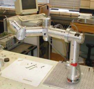
In this Section, using the IRIS configuration 1 shown in Figure 1, some experimental results are introduced to show the effect of trajectory/payload variations on the robotic arm performance. The PID gains of each of the 4 d.o.f were self-tuned to achieve the best tracking performance. In this set of experiments, all 4 d.o.f were actuated and the following operating conditions were tested: (1) symmetric sinusoidal trajectory with (i) no load, and (ii) 3.4 Kg load; (2) asymmetric sinusoidal trajectory with (i) no load, and (ii) 2.35 Kg load; and (3) random trajectory with (i) no load, and (ii) 3.4 Kg load. For the first operating condition, with a load of 3.4 Kg, the maximum tracking error of joint 1 increased by 89.36%. For joint 2, again, the maximum tracking error increased by 20% when the load is added. For joint 3, the average tracking error is doubled from 0.350 to almost 0.70 when the load is added. Joint 4 was also affected when the load was introduced showing an increase of about 32% in the tracking error. In the third test, the loading of 3.4 Kg was retained and the sinusoidal tracking trajectory was replaced by a random trajectory. The gains were kept fixed to determine the effect of the trajectory change on the tracking performance under no load and loading conditions. Joint 1 showed a 30% increase in the maximum tracking error under 3.4 Kg load. However, with the same load and fixed gains, the maximum tracking error of joint 1 is less for a random trajectory than for a sinusoidal trajectory. Joint 2 showed a 34.55 % increase in the maximum tracking error when the load is added.
For joint 2, in presence of the load, the maximum tracking error of the random trajectory is 20% higher than the sinusoidal trajectory. For the random trajectory, joint 3 showed a 42.5% increase in the maximum tracking error when the load was added. Again, with load, and using fixed PID gains, the error of the random trajectory is much higher than the sinusoidal trajectory for joint 3. For joint 4, the maximum tracking error is doubled from -0.004 (rad) to -0.008 (rad) when the load was added.
Fig. 1: IRIS configuration 1
More experiments were performed on the IRIS configuration 2 shown in Figure 2. In this configuration the orientation of joint 4 was changed. PID gains of each of the four joints were re-tuned to achieve an acceptable performance for this specific configuration. However, initially, the tuning of the gains for joint 4 was extremely "tricky" due to the significant effect of gravity on its tracking performance under loading conditions. Two experiments were performed: (1) a symmetric trajectory with no load and 2.1 Kg load; and (2) an asymmetric trajectory with no load and 1.2 Kg load. For the first experiment, Joint 1 showed a 5~10% increase in the maximum tracking error when a load of 2.1 Kg load was added. For joint 2, the sum of squared error increased significantly when the load was added. The same phenomenon was experienced for joint 3. For joint 4, the gains were self-tuned on-line to improve the tracking performance for a no load operating condition. Despite that, when the load was added the maximum tracking error of joint 4 significantly increased. For the second set of experiments on this configuration, the PID gains of each of the four joints were re-tuned again prior to the experiment. Because of the light load introduced, i.e., 1.2Kg, the performance of joints 1, 2, and 3 degraded significantly. Moreover, for joint 4, the maximum tracking error increased substantially when the load was added.
IV. CONCLUSION
In this paper, we derived an expression for the filtered tracking error of the end-effector of the IRIS serial manipulator. This expression is derived in the presence of external disturbances in the form of a varying payload at the end-effector. The filtered tracking error expression is a
function of the joint position, velocity, motor torques, and load inertia. From results obtained on two different IRIS configurations, we realize that in most experiments, a payload (as small as 1 Kg) can significantly reduce the tracking performance of some (if not all) degrees-of freedom of the IRIS arm. Furthermore, for some setups, the error of one or more d.o.f can increase substantially when gravity plays a role in magnifying the disturbance force acting upon the manipulator due to the load. Hence, to achieve a desired accurate positioning under any operating condition, either the independent joint servo gains should be re-tuned at the beginning of every new experiment or an adaptive control strategy should be implemented. The explicit expression of the filtered tracking error derived in this paper is meant to facilitate the process of designing an adaptive control strategy for the IRIS arm.
Fig. 2: IRIS configuration 2
REFERENCES
[1] Hui R., Kircanski N., Goldenberg A. A., Zhou C.,
Kuzan P., Wiercienski J., Gershon D., Sinha P., "Design of the IRIS facility- a modular, reconfigurable and expandable robot test bed, IEEE International Conference on Robotics and Automation; Vol.3; pp. 155-160; 1993.
[2] Anderson J. N., Pittelkau M. E., Reflex-action
position control and two-arm load -sharing force control of robot manipulators, Tennessee Tech. Center for Manufacturing Research and Technology Utilization, Report No. MCTR 1-88-1, Jan. 1988.
[3] Slotine J-J., Li W., Stable adaptive control of robot
manipulators, International Journal of Robotics Research, Vol.6, No.3, pp.49-59, 1987.
[4] Goldenberg A. A., Emami M. R., Kinematics and
Dynamics of Robot Manipulators, Handbook of Industrial Robotics, 2nd. Edition, Chapter 6, John Wiley & Sons, pp. 79-98, 1999.
[5] W. W. Melek, Neurofuzzy Control of Modular and
Reconfigurable Robots, Ph.D. Dissertation, University of Toronto, 2002.
![Risiko- & [und] Schutzfaktoren der psychischen Gesundheit humanitärer Einsatzhelfer : eine systematische Literaturübersicht](data:image/gif;base64,R0lGODlhAQABAIAAAP///wAAACH5BAEAAAAALAAAAAABAAEAAAICRAEAOw==)