Designing Durable Vapor-Deposited
Surfaces for Reduced Hydrate Adhesion
The MIT Faculty has made this article openly available. Please share how this access benefits you. Your story matters.Citation Sojoudi, Hossein, Matthew R. Walsh, Karen K. Gleason, and Gareth
H. McKinley. “Designing Durable Vapor-Deposited Surfaces for Reduced Hydrate Adhesion.” Advanced Materials Interfaces 2, no. 6 (March 3, 2015): n/a–n/a.
As Published http://dx.doi.org/10.1002/admi.201500003
Publisher Wiley Blackwell
Version Author's final manuscript
1 DOI: 10.1002/ ((please add manuscript number)) Article type: Full Paper
Designing Durable Vapor Deposited Surfaces for Reduced Hydrate Adhesion
Hossein Sojoudi, Matthew R. Walsh, Karen K. Gleason,* and Gareth H. McKinley*
Dr. Hossein Sojoudi, Prof. Karen K. Gleason
Department of Chemical Engineering, Massachusetts Institute of Technology, 77 Massachusetts Avenue, Cambridge, MA 02139, United States
E-mail: [email protected]
Dr. Hossein Sojoudi, Prof. Gareth H. McKinley
Department of Mechanical Engineering, Massachusetts Institute of Technology, 77 Massachusetts Avenue, Cambridge, MA 02139, United States
E-mail: [email protected] Dr. Matthew R. Walsh
Chevron Energy Technology Company, Flow Assurance Technology 1200 Smith St, Houston, TX, 77018
Keywords: durable surfaces; reduced hydrate adhesion; subcooling effect; bilayer CVD polymers; hydrate-phobicity
The formation and accumulation of clathrate hydrates inside oil and gas pipelines causes severe problems in deep-sea oil/gas operations. In the present work, durable and mechanically-robust bilayer poly-divinyl benzene (pDVB)/poly(perfluorodecylacrylate) (pPFDA) coatings are developed using initiated chemical vapor deposition (iCVD) to reduce the adhesion strength of hydrates to underlying substrates. Tetrahydrofuran (THF) dissolved in water with a wt. % concentration of 0-70 is used to study the formation of hydrates and their adhesion strength. Goniometric measurements of water droplets on the coated substrates exhibit advancing contact angles of 157.8º ± 2.3º and receding contact angles of 131º ± 8º, whereas 70 wt. % THF in water droplets present advancing angle of 85.1º ± 6.1º and receding angle of 48.5º ± 4.9º. The strength of hydrate adhesion experiences a ten-fold reduction when substrates are coated with these iCVD polymers: from 1050±250 kPa on bare substrates to 128±100 kPa on coated ones. The impact of subcooling temperature and time on the adhesion
2
strength of hydrate on substrates is also studied. The results of this work suggest that the THF-water mixture repellency of a given substrate can be utilized to assess its hydrate-phobic behavior; hence, it opens a pathway for studying hydrate-phobicity.
1. Introduction
The formation and accumulation of clathrate hydrate deposits inside oil and gas pipelines causes severe problems in deep-sea oil and gas operations.[1] Clathrate hydrates are non-stoichiometric crystalline solids formed by physical combinations of water and small gas (e.g., methane, ethane, carbon dioxide, propane) or liquid (e.g., cyclopentane, tetrahydrofuran) guest molecules.[2-4] At the appropriate thermodynamic conditions (in most cases corresponding to relatively high pressures and low temperatures), water as the host molecule forms a framework through a hydrogen bonding network of cages which can be occupied by the guest molecules, whose diameter is less than the size of the cavity.[5]
Active methods have been developed to prevent the formation of hydrate inside oil and gas pipelines by applying heat to the pipelines,[6] adding water-miscible alcohols such as methanol to shift the thermodynamic equilibrium away from hydrate formation,[7] and using kinetic inhibitors to delay the crystallization and growth of hydrates.[4, 8] However, these methods are expensive, require substantial power for operation, and may have detrimental environmental consequences.[4, 6, 7, 8] Therefore, surface modification is of great interest for the passive prevention of hydrate formation directly on the surface. Additionally, should any hydrate form, either on the surface or in the bulk, reducing the adhesion strength of the hydrate to the surface is desirable for ease of clearing the blockage.[9] To this end, there is a need for mechanisms enabling deposition of scalable and durable hydrate-phobic coatings which possess required mechanical properties to be applied inside oil and gas pipelines.
In this work, we have developed durable and mechanically-robust bilayer polymer coatings using the initiated chemical vapor deposition (iCVD) technique to reduce the adhesion of hydrates to underlying substrates. iCVD is a deposition technique that enables
3
grafting of polymers to substrates and therefore promotes their adhesion to substrates to be durable against abrasion and erosion.[10-12] Unlike traditional polymer deposition techniques such as spin-coating, dipping, and ink-jet printing, iCVD provides ways to deposit graded polymers, copolymers which do not have common solvents, and multilayered polymers which are covalently bonded at their interface.[13, 14] The conformal nature of the iCVD technique also enables the integration of polymer thin films onto engineering surfaces that have roughened features or nanostructured topography. We recently developed bilayer polymers which are covalently bonded to substrates using an in-situ grafting mechanism.[15] Such bilayer polymers were shown to exhibit enhanced mechanical properties (e.g., elastic modulus and hardness) when compared to other coatings developed using traditional iCVD polymerization, which potentially makes them suitable for industrial applications such as flow assurance strategies by coating inside oil and gas pipelines. Other types of vapor deposition methods have been commercialized for coating the inside of pipes used in the oil and gas industry[16] and it is anticipated that similar process strategies would be successful for iCVD. For applications, including surface modification to improve the release of rubber from the molds used to manufacture tire, the iCVD process has been scaled up to reactors > 1 meter in dimension.[10]
Among numerous compounds known to form hydrates with water, tetrahydrofuran (THF) is attractive for laboratory studies since it is in liquid state at atmospheric pressure and is miscible with water. At atmospheric pressures hydrates form from THF above the freezing temperature of water (up to 4.4 ºC), making them easily distinguishable from ice.[7, 17, 18, 19] Hydrates are known to crystallize in three common structures, I (sI), II (sII), and H (sH), depending on the size and shape of the guest molecules. THF forms a structure II hydrate with water at a composition of 1:17 molar ratio or ~19% by weight.[2, 20] Structure II hydrate is the most-commonly formed solid phase in oil and gas pipelines, and the prevention or mitigation
4
of these structures is currently the most economically-meaningful application of gas hydrate research.[21]
While the crystallization, growth, and aggregation of hydrates have been studied extensively, [4, 7, 19, 22] there are relatively fewer studies focusing on hydrate adhesion to various surfaces. Sloan and coworkers have investigated the formation and adhesion of hydrate particles in a series of studies.[23, 24] They used a micro-mechanical adhesion apparatus to measure adhesion force between already formed hydrate particles,[23, 25] and/or hydrate and ice particles with and without the presence of other liquid (e.g. crude oil).[24] The effects of contact force, contact time, and subcooling temperature were investigated in these studies.[23, 24, 25, 26] Hun et al., studied interaction behavior between hydrate particles and water in a
temperature-controlled hydrocarbon environment utilizing an apparatus fabricated with a microbalance and z-axis stage.[27] Both groups explained the adhesion forces and trends by a capillary bridge forming between the contacting hydrate particles and/or hydrate particles and liquid droplets. More recently, Aspenes et al. studied the adhesion forces between hydrate particles and solid surfaces with various surface energies in the presence of water and/or other petroleum acids in an oil phase. They found that the adhesion force between the hydrate particles and the solid surfaces increases more than ten-fold when the solid surfaces are water-wet.[26] In these studies, hydrate particles were formed by freezing ice particles inside a bath of hydrate-forming liquid and then brought into contact with either similarly formed hydrate particles and/or various solid surfaces. To understand the impact of hydrates crystallization on their adhesion strength, there is a need to study the formation and subsequent adhesion of hydrates on surfaces and investigate the effect of surface energy on their adhesion strength.
Here, we study both the formation and subsequent adhesion of THF hydrates on surfaces coated with iCVD polymers. The composition of THF in water was varied and its impact on the surface tension of the THF-water mixture and contact angle of the THF-water droplets on polymer coated surfaces has been studied. By understanding the phase diagram of
5
the THF-water mixture, the number of experimental measurements required to predict the behavior of a surface at all THF compositions can be minimized. Additionally, our work demonstrates the optimal THF compositions to work with in order to predict the behavior of hydrates over the full range of compositions.
Recently, we reported the deposition and process optimization of iCVD bilayer polymers with enhanced mechanical properties and adhesion to substrates as well as their hydrophobicity/icephobicity.[15] The bilayer polymers consisted of a thick, mechanically-robust and dense polymer base layer, poly-divinyl benzene (pDVB), that is highly cross-linked and then capped with a covalently-attached thin fluorine-containing top layer, poly(perfluorodecylacrylate) (p-PFDA). A linker-free grafting in which covalent chemical bonds form across the substrate-polymer interface was developed to enhance the interfacial adhesion of the bilayer iCVD polymers to the underlying substrates. With this bilayer architecture, the optimized film displayed both high elastic modulus, E, and hardness, H, (E=19.1±1.2 GPa and H = 479.0±7.0 MPa) and excellent Cassie-state hydrophobicity (advancing water contact angle (WCA), 𝜃𝐴=157.8º ± 2.3º, and receding WCA, 𝜃𝑅=131.0º ± 8.0º). In addition, the linker-free grafted bilayer films did not delaminate during nanoscratch tests performed at 5 mN normal loads.[15] Finally, the strength of ice adhesion was reduced by more than six-fold when substrates were coated with these bilayer films as a result of the low surface energy and smoothness of the iCVD coatings.
In the present work, these optimized linker-free grafted iCVD bilayer films are extended into a new area of durable hydrate-phobic surfaces. This important application can leverage what is known about the popular topics of hydrophobic and icephobic surfaces. As discussed earlier, THF is used as hydrate former due to its unlimited solubility in water and ease of hydrate formation. For various concentrations of THF dissolved in water, the formation of hydrates and the subsequent strength of their adhesion on bilayer iCVD polymers are studied. The results of this study indicate that simple measurements of contact
6
angles of THF-water droplets on substrates are a powerful tool to evaluate the adhesion strength of hydrates to such substrates; hence, it can be used as a key parameter for design of hydrate-phobic surfaces.
2. Results and Discussion
Deposition and linker-free grafting mechanism of bilayer CVD polymers were extensively explained in our previous work. Thus, only a summary is presented here. First, the growth substrates were cleaned by treatment with solvents (e.g. acetone and methanol) and then exposed to an oxygen plasma to enhance the surface concentration of hydroxyl species. Then, the substrates were placed in a low pressure iCVD reactor. The subsequent grafting and synthesis proceed in three steps, all performed sequentially in the iCVD chamber without breaking vacuum: 1) in-situ linker-free grafting, 2) deposition of a mechanically-robust cross-linked hydrocarbon network, and 3) deposition of the top fluoropolymer layer.
For the linker-free grafting, tert-butyl peroxide (TBPO) vapors as initiators were exposed to filament arrays kept at Tf = 310ºC to produce methyl radicals[28, 29] which can
abstract hydrogen from the hydroxyl groups on the substrate (which is maintained at Ts =
20ºC) and result in activated radical sites on the surface.[28] These sites will directly react with the vinyl monomers which are introduced next, to produce covalent bonds from the substrate to the organic layer.
Next, divinylbenzene (DVB) monomer was introduced to the reactor without filament heating (Tf = 25ºC) while the substrate was kept at Ts = 20ºC. The initial reaction with the
activated surface sites results in direct grafting of the monomer to the substrate while retaining a free electron for subsequent vinyl polymerization.
For polymerization of the mechanically-robust layer in the second step, DVB, N2, and TBPO were introduced simultaneously to the low pressure reactor while the filament and the substrate were kept at Tf = 250ºC and Ts = 30ºC, respectively.[30] This resulted in deposition of
7
a densely cross-linked DVB polymer (pDVB) with the desired thickness (in the range of 200 nm – 1 µm).
The third and final step is to grow a top surface layer displaying both low surface energy and the desired hydrate-phobicity. For this, poly-perfluorodecylacrylate, poly-(1H, 1H, 2H, 2H-perfluorodecylacrylate) (pPFDA) was introduced to deposit a thin layer of fluorine-rich polymer (either 10 or 40 nm thick). It has been shown that the presence of the densely cross-linked pDVB network underneath a thin pPFDA film can prevent inward reorientation of fluorine groups in pPFDA film when exposed to water and results in a lower water contact angle (WCA) hysteresis.[14] Therefore, around 10 nm of pPFDA on cross-linked pDVB is favorable to obtain a bilayer film (abbreviated as LFG-BL (10 nm)) with very low WCA hysteresis (3.8º ± 0.5º). On the other hand, a relatively thicker layer of pPFDA (~ 40 nm) grafted to underlying pDVB was found to provide full coverage of the bilayer film (abbreviated as LFG-BL (40 nm)) by the fluorinated groups resulting in higher values of the advancing WCA (157.8º ± 2.3º) and relatively high receding WCA (131.0º ± 8.0º). Therefore, two sets of bilayer films (LFG-BL (10 nm) and LFG-BL (40 nm)) were developed in this work to investigate the impact of both contact angle and contact angle hysteresis on the subsequent adhesion of THF/water hydrate deposits.
Fourier transform infrared spectroscopy (FTIR) and X-ray photoelectron spectroscopy (XPS) were performed on the bilayer polymer and confirmed successful deposition of both pPFDA and pDVB components through the presence of bands corresponding to carbonyl, carbon-fluorine bonds, and phenyl groups in the FTIR spectra.[15] The properties of the LFG-BL films can be summarized as follows. Optical profilometer measurement gave root mean square (Rq) roughness values of 18.9±5.4 nm and 19.2±4.8 nm for LFG-BL (40 nm) and LFG-BL (10 nm) coatings, respectively.[15] Elastic modulus and hardness were obtained from nanoindentation measurements and found to be E = 19.1±1.2 GPa and H = 479.0±7.0 MPa for LFG-BL (40 nm) and E = 18.1±1.0 GPa and H = 463.0±4.5 MPa for LFG-BL (10 nm). It is
8
important to note that the elastic modulus and hardness mostly depend on the highly dense pDVB network and not on the properties of the thin top layer pPFDA film; therefore, LFG-BL (40 nm) and LFG-LFG-BL (10 nm) showed comparable elastic modulus and hardness values. 2.1. THF-Water Wettability of Surfaces
Water is an extensively hydrogen-bonded fluid and the addition of cyclic ethers such as tetrahydrofuran leads to the formation of clathrates with the ether molecules being surrounded by water molecules.[31] Solutions of THF-water mixture (0, 10, 19, 50, and 70 wt. % THF in water or χTHF =
wt. THF
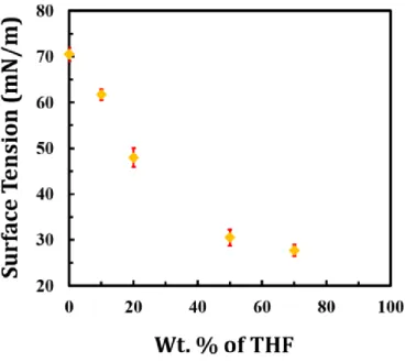
Total wt.= 0, 0.1, 0.19, 0.50, and 0.70) were made and their surface tension and their impact on wettability of surfaces (iCVD polymer coated and bare substrates) were studied. The surface tension values of the THF-water mixtures were measured through the pendant drop method.[32] Measurements were performed rapidly (less than 10 seconds) to minimize impact of air exposure on the THF-water droplets. The surface tension values were averaged from measurements of ten droplets for a given composition of THF in water. Variation of the surface tension with wt. % of THF dissolved in water is illustrated in Figure S1 in Supporting Information. The measured surface tension of DI water was within the acceptable range, 70.5±1.5 mN/m, and used for verification of surface tension data for other THF-water mixtures. As expected, the surface tension of the THF-water mixture decreases with an increase in the wt. % of THF in water.[31]
The wettability of bare and iCVD polymer coated substrates also displayed a dependence on the wt. % of THF in water. The wettability of a surface by a liquid can be enhanced by either reducing the liquid surface tension or increasing substrate surface energy. Contact angle measurements are a useful tool for probing interfacial interactions between solid and liquid. Wettability of a solid surface is characterized by the contact angle measured between the liquid drop and the surface. In a typical solid-liquid-vapor system (such as a sessile drop of liquid placed on a solid surrounded by air) the contact angle can also be used
9
to measure the work of adhesion.[33] Wetting of a surface by a particular liquid depends on the relative magnitude of the cohesive molecular forces that exist within the liquid and adhesive interaction between liquid and the solid. Strong adhesive forces between a liquid and solid result in a liquid drop spreading across the surface. Strong cohesive forces within the liquid prevent contact with the surface. Strong adhesion and weak cohesion result in a high degree of wetting, a hydrophilic condition with low measured contact angles. Conversely, weak adhesion and strong cohesion result in hydrophobic conditions with high measured contact angles and poor wetting.[34]
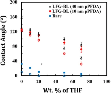
Figure 1 shows advancing and receding contact angles of THF-water mixture droplets on coated and bare substrates. It is evident that with an increase in the wt. % of THF in the mixture (higher χTHF ) both the advancing and receding contact angles of the THF-water droplets on all of the substrates decrease because of the adhesive interaction between the substrate and the liquid. Linker–free grafted bilayer pDVB/pPFDA polymer with ~ 40 nm thick pPFDA (LFG-BL (40 nm)) presents both a high advancing (157.8º ± 2.3º) and high receding (131.0º ± 8.0º) water contact angle. Addition of 70 wt. % THF in water ( χTHF = 0.70) results in lower advancing (85.1º ± 6.1º) and receding (48.5º ± 4.9º) THF-water contact angles on LFG-BL (40 nm). However, the coating does not become fully wetted due to the high density of fluorine-containing groups on the coatings. In contrast, bare substrates become wet spontaneously with the THF-water mixture.
The goniometer measurements on linker-free grafted bilayer pDVB/pPFDA with a smaller pPFDA top coat thickness of approximately 10 nm (LFG-BL (10 nm)) resulted in the advancing and receding water contact angles of 125.8º ±1.1º and 122.0º ±2.0º, respectively. Droplets of 70 wt. % THF in water solution exhibited advancing and receding contact angle of 71.8º ±8.2º and 32.0º ±5.3º on this samples, respectively. The reduction in the advancing and receding contact angles on LFG-BL (10 nm) when compared to LFG-BL (40 nm) arise due to the reduced surface coverage of fluorine-containing PFDA film in the bilayer
10
polymeric. A slight decrease in contact angle hysteresis (advancing contact angle minus receding contact angle) was also observed. Overall, the thicker LFG-BL (40 nm) coating shows better THF-water mixture repelling nature when compared to the thinner LFG-BL (10 nm) and suggests that the former coating is likely to perform better for reduction of THF hydrate adhesion strength.
2.2. THF Hydrate Formation and Strength of Adhesion to Surfaces
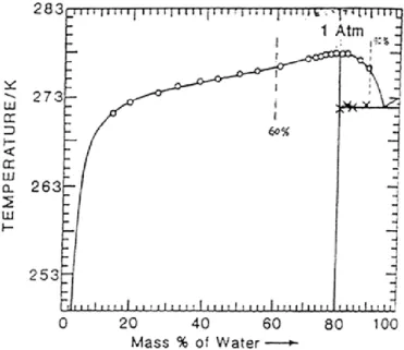
We next study the formation and accumulation of THF hydrates on coated surfaces with a systematic variation surface energies. Natural gas hydrates usually form at elevated pressures due to their low solubility in water. Mass transfer at the liquid-gas interface controls nucleation and crystal growth of these hydrates.[7, 8, 35] THF-water hydrate is often used as a model system for the study of hydrate formation because the mass transfer effects are eliminated, and because the necessity of high-pressure is also eliminated.[7] The THF-water phase diagram is a useful tool to study the formation of THF hydrates (Supporting Information, Figure S2). THF is miscible in water and forms a structure II hydrate with water at a composition of 1:17 molar ratio (~19 wt. % THF dissolved in water, χTHF = 0.19). This hydrate melts at a temperature of 4.4 ºC (277.4 K) at 1 atm.[2] According to the phase diagram, when the THF in water is less than ~19 wt. % ( χTHF < 0.19), the THF-water mixture converts to a mixture of ice and hydrates when cooled down to low temperature (≤ 271.0 K) at atmospheric pressure (denoted regime I). On the other hand, a THF-water mixture with more than ~19 wt. % THF ( χTHF > 0.19) will partially converts to hydrates with some unfrozen THF-rich supernatant solution when cooled to a low temperature (denoted regime II).[2]
Here, we study the formation of hydrates and/or ice and the strength of their adhesion to bare and polymer-coated substrates in both regimes. A custom-built adhesion testing apparatus housed inside a nitrogen-containing glove box was used for this purpose.[36] Various wt. % of THF dissolved in water ( χTHF = 0, 0.10, and 0.19 in regime I and χTHF = 0.19,
11
0.50, and 0.70 in regime II) were prepared and poured into glass cuvettes and were frozen on test substrates (bare and polymer-coated surfaces) for several hours at -15 ºC to ensure formation of hydrates and/or ice on substrates.[9] Care was taken to minimize air exposure of THF-water, and time elapsed between its preparation and pouring into cuvettes for strength of adhesion measurements in order to prevent THF evaporation.
The lateral force required to de-adhere frozen cuvettes was recorded and converted into a measure of the shear strength of ice/hydrate adhesion by dividing over the cuvette area. The measurements were performed on twenty samples of each type and subsequently averaged. Sample-to-sample variations in the measured adhesion strengths can be large due to the dominant role of local flaws in this failure test and variations in the nature of the ice/hydrate formed at the interface with the substrate.
2.2.1. Regime I: 0 ≤ 𝜒𝑇𝐻𝐹 ≤ 0.19
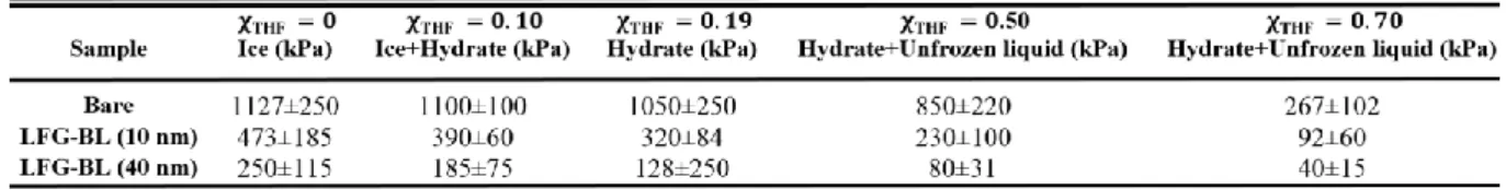
At a composition of 19 wt. % THF in water the mixture turns fully into hydrates when cooled down to low temperature at atmospheric pressure.[4, 23, 31, 35] The strength of the hydrate adhesion measured on bare substrates was 1050±250 kPa, whereas the corresponding value on LFG-BL (10 nm) and LFG-BL (40 nm) were measured to be 320±84 kPa and 128±250 kPa, respectively. This indicates that the polymer coating with the greater enrichment of fluorine-containing groups LFG-BL (40 nm) resulted in an approximately ten-fold reduction in the strength of hydrate adhesion when compared to bare substrates. The reduction in adhesion by LFG-BL (40 nm) was found to be superior to that of LFG-BL (10 nm), consistent with better THF-water repelling nature of the LFG-BL (40 nm) as shown in Figure 1. At compositions of χTHF < 0.19 cooling to low temperatures results in formation of both ice and hydrate. Based on the THF-water phase diagram using the lever rule,[2] a composition of χTHF ≊ 0.10 water turns into approximately 50 % ice and ~50 % hydrates when cooled to low temperatures. At this concentration of THF, the strength of the ice/hydrate mixture adhesion on bare substrates was measured to be 1100±100 kPa, whereas on LFG-BL (10 nm) and LFG-BL (40 nm) the
12
values were 390±60 kPa and 185±75 kPa, respectively. Again we find that the fluorinated polymer bilayer coating resulted in substantially lowered adhesion strength of ice/hydrate mixture (close to ten-fold reduction).
Comparing adhesion strength of ice/hydrate mixture with that of pure hydrate on a given substrate indicates that the addition of ice results in enhanced adhesion strength of the solid (ice and/or hydrate) to both bare and coated substrates. Finally, the cuvettes were filled with only water and the adhesion of pure ice was measured on the bare and polymer coated substrates. The strength of ice adhesion was 1127±250 kPa on bare substrates and 473±185 kPa and 250±115 kPa on the LFG-BL (10 nm) and the LFG-BL (40 nm) coated substrates, respectively. These values are summarized in Table 1.
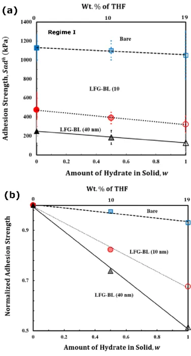
Figure 2a shows the measured strength of solid (ice and/or hydrate) adhesion plotted vs. the amount of hydrate in solid, w, (0-1) which can be related to χTHF (0-0.19) using the THF-water phase diagram.[2] A linear fit to the adhesion strength data for a given substrate (bare or polymer coated) leads to a relation that enables us to express the adhesion strength of ice/hydrate mixture as a function of the individual values of ice adhesion strength and hydrate adhesion strength: 𝑆 𝑎𝑑ℎ = [(1 − 𝑤) × 𝑆 ice 𝑎𝑑ℎ+ 𝑤 × 𝑆 hydrate 𝑎𝑑ℎ ] (1)
where 𝑆𝑎𝑑ℎ is the measured strength of crystal solid (ice/hydrate mixture) adhesion, 𝑆 ice𝑎𝑑ℎ is the strength of ice adhesion, and 𝑆 hydrate𝑎𝑑ℎ is the strength of hydrate adhesion. The linear fits through the data show excellent correlation and confirm the validity of the proposed relation (𝑅 bare2 = 0.97, 𝑅 LFG−BL (10 nm)2 = 0.99, and 𝑅 LFG−BL (40 nm)2 = 0.99).
This relation can be useful to obtain the adhesion strength of solid crystals formed from THF/water compositions with 0 < χTHF < 0.19 on substrates with given surface energy. The average values of the measured adhesion strength of hydrate and/or ice/hydrate mixture were also normalized using the average values of the pure ice adhesion strength measured for
13
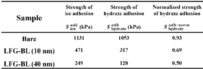
a given substrate, as shown in Figure 2b. The results indicate that the ratio of hydrate adhesion strength to ice adhesion strength is reduced from approximately 0.93 on bare substrates to ~ 0.67 and ~ 0.51 on LFG-BL (10 nm) and LFG-BL (40 nm) coated substrates, respectively. This indicates that the reduction in the adhesion strength of THF hydrate when compared to adhesion strength of ice is enhanced on surfaces with higher fluorine concentration. Similarly, through a linear fit to the normalized adhesion strength data, the normalized strength of crystal solid (ice/hydrate mixture) adhesion, 𝑆𝑎𝑑ℎ−𝑛𝑜𝑟𝑚, can be obtained using 𝑤 and the normalized strength of hydrate adhesion, 𝑆 hydrate𝑎𝑑ℎ−𝑛𝑜𝑟𝑚.
The values obtained from these linear fits for 𝑆 ice𝑎𝑑ℎ, 𝑆 hydrate𝑎𝑑ℎ , and 𝑆𝑎𝑑ℎ−𝑛𝑜𝑟𝑚 are presented in Table 2 for bare, LFG-BL (10 nm), and LFG-BL (40 nm) coated substrates.
2.2.2. Regime II: 𝜒𝑇𝐻𝐹 ≥ 0.19
When the concentration of THF in water exceeds 19 wt. %, upon freezing the THF-water mixture will partially convert to hydrates at low temperature (-15 ºC) with some residual unfrozen liquid. The composition of this supernatant unfrozen liquid depends on the THF wt. % in the mixture. The temperature was reduced to as low as -20 ºC and maintained for ~ 4h but the amount of unfrozen liquid observable with the naked eye did not change. This is in accord with the THF-water phase diagram[2] which suggests presence of two phases (hydrate and unfrozen supernatant liquid) at these temperatures at atmospheric pressure (freezing point of pure THF is -108.5°C at 1 atm). Mixtures of 50 and 70 wt. % THF in water ( 𝜒𝑇𝐻𝐹 = 0.50 𝑎𝑛𝑑 0.70) were prepared and poured into cuvettes for adhesion strength tests similar to the protocols explained earlier. Similar to the measurements in regime I, the strength of adhesion of the hydrate/unfrozen liquid samples to twenty samples of various bare and coated substrates were obtained to minimize statistical variations.
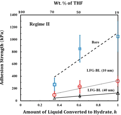
Figure 3 shows the adhesion strength values vs. the amount of liquid converted to hydrates, 0≤ h≤ 1. The amount of hydrate formed from a THF-water mixture was calculated from the
14
THF-water phase diagram using the lever rule. For a composition of 50 wt. % THF in water ( 𝜒𝑇𝐻𝐹 = 0.50) approximately 61 % of the liquid turns into hydrate (h ≊ 0.61). At this THF concentration, the strength of hydrate/unfrozen liquid adhesion on bare substrates was measured to be 850±220 kPa, whereas on LFG-BL (10 nm) and LFG-BL (40 nm) the strength of adhesion was reduced to 230±100 kPa and 80±31 kPa, respectively. An increase in the wt. % of THF in water to 𝜒𝑇𝐻𝐹 = 0.70 results in approximately 35 % hydrate formation (h ≊ 0.35). As expected this leads to a decrease in the adhesion strength of hydrate/unfrozen liquid on all substrates from 267±102 kPa on bare surface to 92±60 kPa on the LFG-BL (10 nm), and 40±15 kPa on LFG-BL (40 nm) coatings. These values are summarized in Table 1. Linear regression of the hydrates/unfrozen liquid adhesion strength data plotted vs. the amount of liquid converted to hydrates, h, approximately passes through the origin with the following relation:
𝑆 ℎ𝑦𝑑𝑟𝑎𝑡𝑒/𝑢𝑛𝑓𝑟𝑜𝑧𝑒𝑛 𝑙𝑖𝑞𝑢𝑖𝑑𝑎𝑑ℎ = ℎ × 𝑆 ℎ𝑦𝑑𝑟𝑎𝑡𝑒𝑎𝑑ℎ (2)
where 𝑆 ℎ𝑦𝑑𝑟𝑎𝑡𝑒/𝑢𝑛𝑓𝑟𝑜𝑧𝑒𝑛 𝑙𝑖𝑞𝑢𝑖𝑑𝑎𝑑ℎ is the adhesion strength of the hydrate/unfrozen liquid mixture which forms when the THF wt. % in water is 𝜒𝑇𝐻𝐹 > 0.19 and h is the fraction of the liquid that is converted to hydrates.
It has been shown that hydrophobic hydrate formers allow hydrate crystals to generally form only at the interface of the guest-water phase, whereas THF mixed with water allows hydrate crystals to form and grow anywhere within the confines of the solution.[4, 7, 35] The linear relation between the adhesion strength and ℎ confirms an overall uniform distribution of hydrates and unfrozen THF-water mixture within the cuvettes during the adhesion measurements. For a given THF wt. % in water on a given substrate ( χTHF ), h can be obtained from the THF-water phase diagram, and the strength of the hydrate that forms from that liquid below a critical temperature can be obtained from the above relation. In addition, it can be concluded that the compositions of the hydrates and the strength of their
15
adhesion to various substrates (bare and polymer coated) are comparable and independent of the wt. % of THF in water that form those hydrates at low temperature.
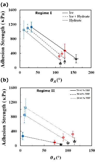
2.3. Relation between Surface Wettability and the Strength of Ice/Hydrate Adhesion As explained earlier, when 0 ≤ χTHF ≤ 0.19 freezing results in formation of both hydrate and ice (indicated as regime I) whereas for χTHF ≥ 0.19 it causes the formation of hydrate with some residual unfrozen liquid (denoted regime II). Figure 4 (a) shows the adhesion strength of ice/hydrate (in regime I) and (b) hydrate/unfrozen liquid (in regime II) plotted vs. the advancing contact angle of the liquid THF-water mixture, 𝜃𝐴, on both coated (LFG-BL (40 nm) and (LFG-BL (10 nm) and bare substrates. The average strength of ice/hydrate adhesion (in regime I) and hydrate/unfrozen liquid adhesion (in regime II) reduces linearly as the advancing contact angle of THF-water mixture increases due to improved wettability of surfaces.
It has been argued that the wettability and motion of liquid droplets on surfaces involve both shear and tensile contributions.[34] While the shear contribution is related to sliding and/or roll-off of liquid droplets from surfaces, the tensile force required to detach a liquid droplet from a solid surface depends on the receding contact angle.[36] This is related to the work of adhesion between a liquid droplet (e.g. the THF-water mixture of interest in this study) and the underlying substrate, and can be calculated from the Young-Dupré equation: [34]
𝑊𝑎𝑑ℎ = 𝛾𝐿𝑉(1 + cos 𝜃𝑅) (3)
where 𝑊𝑎𝑑ℎ is the work of adhesion between a liquid droplet (e.g. THF-water mixture) and underlying substrate; 𝛾𝐿𝑉 is the surface tension, between liquid (e.g. THF-water mixture) and air; and 𝜃𝑅 is the receding contact angle of THF-water liquid droplets on a substrate.
16
A high receding contact angle for a drop of THF-water mixture on a substrate, 𝜃𝑅, corresponds to low pull-off forces under tensile (normal) loading conditions. To reflect the importance of this ‘tensile hydrophobicity’, we present the strength of ice/hydrate adhesion data by plotting them vs. the work of adhesion between a liquid droplet (e.g. THF-water mixture) and a given substrate (bare and polymer coated) (Supporting Information, Figure S3 a and b). For 0 ≤ χTHF ≤ 0.19 (regime I), the ice/hydrate adhesion strength was plotted vs. the work of adhesion between a liquid droplet, which was used for the formation of ice/hydrate, and underlying substrate. The average strength of ice/hydrate adhesion linearly reduces with decreases in the work of adhesion (calculated from eq. 3). This linear reduction suggests that the adhesion strength of the solid ice/hydrate correlates well with the work of adhesion between a liquid THF-water droplet (used to form the ice/hydrate) and the underlying substrate in this regime.
In regime II, χTHF ≥ 0.19, the adhesion strength of the hydrate/unfrozen supernatant liquid was plotted vs. the work of adhesion between a ~19 wt. % THF in water droplet and underlying substrate (Supporting Information, Figure S3 b). These data suggest that liquid drops with a composition of 19 wt. % THF in water ( χTHF = 0.19) have to be used as a probe fluid to obtain the correct work of adhesion relevant to the strength of hydrates/unfrozen liquid adhesion on substrates.
Overall, good correlation between the measured hydrophobicity of THF-water droplets placed on the deposited polymer films and their measured hydrate-phobic behavior is observed. These results confirm that smooth fluoropolymer surfaces with both high advancing and receding contact angles for liquid THF-water mixtures are optimal for reducing the strength of ice/THF hydrate adhesion. The reduction in the strength of ice adhesion reported in this work is higher than those values reported elsewhere for soft fluorinated polymer coatings.[36, 37] Furthermore, the high modulus and stiffness of the cross-linked polymer
17
networks that are deposited by the iCVD process provide greatly enhanced mechanical resistance to wear and erosion processes that are characteristic of industrial applications. 2.4. Subcooling Effect
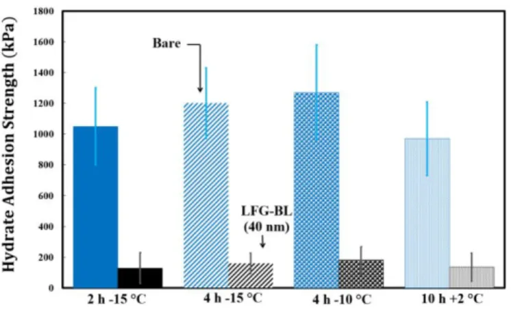
The combination of subcooling temperature and time is important in the formation of THF hydrates. When previously-formed hydrate particles are brought into contact with each other and/or with a desired test substrate, subcooling plays an important role in the adhesion strength that develops between two interacting parts.[23, 24, 26] It has been shown that the growth rate of hydrates increases as subcooling temperature and/or time increases.[17, 35] To investigate the impact of subcooling temperature and time on the hydrate adhesion strength, a solution with χTHF = 0.19 was prepared and used to study formation of THF hydrates on bare and polymer coated substrates (LFG-BL (40 nm)) under various solidification condition. Figure 5 shows the adhesion strength of the hydrate formed under different subcooling temperate and time on bare and LFG-BL (40 nm) coated substrates. Both the increase in cooling time from 2h to 4h and the cooling temperature from -15ºC to -10ºC did not cause noticeable change in the hydrate adhesion strength. To ensure the presence of only hydrates, they were intentionally allowed to nucleate above the melting point of ice (+2ºC) for a period of 10 h. The measurements were performed on bare and LFG-BL (40 nm) coated substrates and hydrate adhesion strength comparable to the previous values presented above in section 2.2.1 were obtained. The hydrate adhesion strength values on LFG-BL (40 nm) coated substrates normalized by the hydrate adhesion strength on bare substrates (Supporting Information, Figure S4). When represented in this form it shows that the substrate coating results in ten-fold reduction in hydrate adhesion strength independent of the thermal condition at which the hydrates form. Small variations in the measured strength of hydrate adhesion formed at different cooling temperature or time might be due to changes in the hydrate number.[38] Despite using the same wt. % THF in water for all the tests( χTHF = 0.19) some of the ice water cages might not be occupied with the guest molecule, THF. Once the hydrates
18
form and are deposited on the fluoropolymer bilayer films, their adhesion strengths are comparable regardless of their formation condition.
2.5. Durability of Coatings
One of the major concerns for developing effective hydrate-phobic coatings is achieving the necessary durability that is required for industrial applications. The surface properties of most polymer coatings degrade after undergoing repeated cycles of ice and/or hydrate formation and detachment. To investigate the durability of the coatings, we characterized the mechanical, surface, and hydrate-phobic properties of the coatings after two cycles of hydrate formation and detachment. To this end, substrates that were used for the formation of THF hydrates (using ~19 wt. % THF in water) were re-used for another set of hydrate formation and adhesion strength measurements.
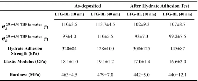
The hydrate adhesion strength on re-used LFG-BL (10 nm) and LFG-BL (40 nm) substrates were found to be 308±125 kPa and 145±87 kPa, respectively, which are within the same range of values obtained on as-deposited coatings (320±84 kPa for LFG-BL (10 nm) and 128±100 kPa for LFG-BL (40 nm), respectively). Advancing and receding contact angles of THF water droplets with χTHF = 0.19 were also re-measured after one hydrate adhesion/de-adhesion cycle on polymer coatings. The measured values were again within the same range of those obtained from measurements on as-deposited samples, as shown in Table 3. Elastic modulus and hardness measurements were performed on as-deposited coatings, and, after one cycle of hydrate adhesion tests and comparable values were obtained (see Experimental Section).
In addition, scanning electron microscopy with energy dispersive X-ray spectrometer, SEM-EDS (JEOL 6010LA) was applied to verify the wettability and mechanical property results. A ‘+‘ crossmark was intentionally created on the sample prior to SEM-EDS to ensure EDS mapping with minimal drift in images, which can happen due to possible charge accumulation. SEM-EDS micrograph and maps of distribution of elements on as-deposited
19
coatings and after one hydrate adhesion/de-adhesion cycle indicates that the film is uniformly rich in fluorine and carbon over large areas (Supporting Information, Figure S5). These data indicate that the hydrate-phobic coatings developed in this study remain functional even after freezing/hydrate deposition and de-adhesion cycle. In future tests the performance of these iCVD polymer coatings will be studied under extended cycles of hydrate formation and detachment and their durability evaluated after long-term contact with aqueous media and atmospheres with high humidity.[39]
3. Conclusion
In conclusion, substrates coated with bilayer polymer films consisting of a high cross-link density network toppe with a 40 nm layer of fluorine rich polymer showed up to ten-fold reduction in the average strength of hydrate adhesion. Experimental measurements of adhesion strength of ice/hydrate mixtures were well correlated using a relationship based on the adhesion strength of pure ice and pure hydrate. Thus, by measuring only the later two pure component values, the adhesion value for any arbitrary mixture can be predicted. The measured adhesion strengths of ice, hydrate, and ice/hydrate mixtures were found to correlate well with the work of adhesion between liquid droplets used in their formation (either water or THF-water mixture) and underlying substrate. We showed that a solution of with a composition of 19 wt. % THF in water has to be used as a probe liquid for the evaluation of the adhesion strength of hydrates. The subcooling temperature and time of exposure were found to have no statistically significant impact on the adhesion strengh of hydrates. This indicates that once the hydrates form and are deposited on the surfaces, their adhesion strengths are comparable regardless of their formation condition. The coatings developed remained robustly hydrate-phobic after one cycle of formation and detachment of hydrates and have future potential for coating inside oil and gas pipelines for deep-sea operations. 4. Experimental Section
20
iCVD coatings: in-situ grafting and iCVD polymerizations were carried out in a custom-built
cylindrical reactor (diameter 24.6 cm and height 3.8 cm), supporting an array of 14 parallel chromoalloy filaments (Goodfellow) suspended 2 cm from the stage.[11, 13] The reactor was covered with a quartz top (2.5 cm thick) that allows real-time thickness monitoring by reflecting a 633 nm He-Ne laser source (JDS Uniphase) off the substrate/polymer and recording the interference signal intensity as a function of time. The reactor was pumped down by a mechanical Fomblin pump (Leybold, Trivac) and the pressure was monitored with a MKS capacitive gauge. The liquid monomers (1H, 1H, 2H, 2H-perfluorodecyl acrylate, PFDA, 97% Aldrich) and (divinylbenzene, DVB, 80% Aldrich) and the initiator (tert-butyl peroxide, TBPO, 98% Aldrich) were used as received without further purification. TBPO was kept at room temperature (Tf = 25ºC) and was delivered into the reactor through a mass flow
controller (1479 MFC, MKS Instruments) at a constant flow rate of 3 sccm during grafting, and 3 sccm and 1 sccm in DVB and PFDA during polymerization, respectively. Methyl radicals were formed through heating the filaments at Tf = 310ºC during grafting using a DC
power supply (Sorensen), whereas initiator radicals (TBO) were created by breaking only the labile peroxide bond of the TBPO at filament temperature of Tf=250ºC during polymerization.
PFDA and DVB were vaporized in glass jars that were heated to 80ºC and 60ºC, respectively and then introduced to the reactor through needle valves at constant flow rates of 0.1 and 1 sccm, respectively. The substrate temperature was kept at Ts = 20ºC during grafting and 30ºC
during polymerization (within ±1ºC) using a recirculating chiller/heater (NESLAB RTE-7). All of the temperatures were measured by K-type thermocouples (Omega Engineering). The working pressure was maintained at 800 mTorr during grafting and 650 mTorr and 300 mTorr in DVB and PFDA polymerization, respectively, using a throttle valve (MKS Instruments). Prior to in-situ grafting, silicon wafers (Wafer World Inc.) were first cleaned by sonication in acetone and isopropanol each for 5 minutes, followed by rinsing in DI water (>16 MOhm-cm).
21
The surfaces were then treated with oxygen plasma for 10 minutes for further cleaning and for creating surface hydroxyl groups prior to transfer into iCVD reactor.
water surface tension and contact angle measurements: Surface tension of
THF-water and contact angles were measured using a goniometer equipped with an automated dispenser (Model 500, ramé-hart). The surface tensions of THF-water mixtures were obtained through pendant drop method.[32] Measurements were performed rapidly to minimize impact of air exposure on THF-water droplets. The surface tension values were averaged from measurements of ten droplets for a given wt. % of THF in water. Advancing and receding contact angles were measured with the sessile drop method by depositing a THF-water droplet of 2-3 μL on the surface, then increasing the volume by 0.15 μL increments until advancement in the liquid meniscus was observed and then decreasing by the same rate until receding motion was seen. Advancing contact angles were considered as the maximum angles observed during the droplet growth, while receding contact angles were measured in correspondence of the drop profile just before the interface receded. Each contact angle value was averaged from measurements of ten droplets of a given THF-water mixture distributed across the sample.
Strength of ice/hydrate adhesion measurements: The strength of crystal solids (ice
and/or hydrate) adhesion was measured using a custom-built ice adhesion set up whose details are described elsewhere.[36, 40] The samples were cut into 1.5 cm × 1.5 cm pieces and clamped to a base plate. Then, glass cuvettes with a 1 cm × 1 cm cross section ~90% filled with THF-water mixture (0, 10, 19, 50, and 70 wt. % THF in THF-water) were inverted on them and clamped. Care was taken to remove any possible liquid residue on the substrate around the cuvettes. The entire plate was cooled at a rate of 2°C per second to desired temperature on a Peltier plate (TECA Corporation, model LHP-800CP) in a low-humidity nitrogen atmosphere (humidity < 5%) and was maintained at this temperature for at desired time to ensure formation of crystal solids (ice and/or hydrates) within the cuvettes. The probe of a force
22
transducer (Imada, model ZP-44) was used to apply a shear force to the cuvettes, and the maximum force required to fracture the crystal solid-substrate interface was recorded. The probe was located about 1.3 mm above the substrate surface to minimize torque on the ice sample. This distance was maintained the same for all samples with the same substrate type. The force measurement tests were performed on twenty samples of each type to minimize statistical variations. The maximum measured forces at the crystal solid-substrate break point were converted to a measure of the shear strength of solid (ice and/or hydrate) adhesion by dividing over the known cross-section area of the ice-substrate interface (1 cm2).
Elastic modulus and hardness measurements: A Nanovea mechanical tester (M1
P-Nano/AFM) was used during the nanoindentation test to obtain elastic modulus and harness of the polymer coatings. The indenter-microscope calibration was performed using a copper sample with a maximum load of 20 mN and indenter approach speed of 30 µm/min. Depth and compliance calibration was performed on a fused silica sample with a Young’s modulus of 72 GPa and Poisson’s ratio of 0.17. A conical diamond indenter tip (Young’s modulus = 1140 GPa and Poisson’s ratio = 0.07) with a radius of R=10 μm was used during all indentations. All of the polymer films used in the nanoindentation experiments were more than 1 μm thick. This was achieved by increasing the thickness of pDVB, while keeping the pPFDA thickness in the same range (10 or 40 nm thick). A maximum indentation depth of 25-150 nm was used to eliminate the possibility of substrate effects which complicate the subsequent analysis. In addition, exploratory tests were performed to ensure that the normal load did not experience a sudden change by a slight increase in the maximum penetration depth indicating that any underlying substrate effect was very minimal. A 4 × 4 grid was used during the indentation of the polymers, with 10 μm separation in both directions between indentations. The ASTM E2546 (ISO 14577) procedure was used by the software to obtain elastic modulus and hardness of the polymers for 16 indentations per sample. Maximum load, load rate, and the creep time were changed to evaluate the time response to loading of the
23
polymers. Finally, a maximum load of 0.40 mN with 0.8 mN/min rate and creep time of 5 seconds were applied throughout the indentation measurements.[15] This ensured appropriate deformation of the polymer networks during loading/unloading cycles and enabled a linear fit to the load-penetration curves during unloading. The Poisson’s ratio for all of the polymers was assumed to be the same and equal to 0.5.[41] A contact load of 0.05 mN was used during the nanoindentation measurements and the recording of the data were stopped once the normal load reached the contact load.
SEM-EDS imaging: Polymer-coated substrates were sputter-coated with 5 nm of gold
(Denton Desk V), and images were obtained by SEM (JEOL 6010LA) with an acceleration voltage of 15 kV. A high acceleration voltage was used to allow mapping without charge accumulation and drift of the images during the mapping. The black and white SEM image is intentionally out of clear focus to optimize the EDS analysis. The black and white images are computer-colored with assigned color schemes for specific elements. These images acquired on as-deposited coatings and after one cycle of hydrate formation, adhesion, and de-adhesion. Supporting Information
Supporting Information is available from the Wiley Online Library or from the author. Acknowledgements
The authors gratefully acknowledge support from the Chevron-MIT Energy Initiative program.
Received: ((will be filled in by the editorial staff)) Revised: ((will be filled in by the editorial staff)) Published online: ((will be filled in by the editorial staff))
24
[1] P. T. Beurskens, G. A. Jeffrey, J. Chem. Phys. 1964, 40, 906; S. Gao, Energy & Fuels 2008, 22, 3150.
[2] Y. A. Dyadin, I. V. Bondaryuk, L. S. Aladko, Journal of Structural Chemistry 1995,
36, 995.
[3] P. Bollavaram, S. Devarakonda, M. S. Selim, E. D. Sloan, in Gas Hydrates:
Challenges for the Future, Vol. 912 (Eds: G. D. Holder, P. R. Bishnoi), 2000, 533.
[4] P. W. Wilson, D. Lester, A. D. J. Haymet, Chemical Engineering Science 2005, 60, 2937.
[5] A. F. Heneghan, P. W. Wilson, G. M. Wang, A. D. J. Haymet, J. Chem. Phys. 2001,
115, 7599.
[6] A. K. Sum, C. A. Koh, E. D. Sloan, Ind. Eng. Chem. Res. 2009, 48, 7457; B. C. Gbaruko, J. C. Igwe, P. N. Gbaruko, R. C. Nwokeoma, J. Pet. Sci. Eng. 2007, 56, 192.
[7] S. Devarakonda, A. Groysman, A. S. Myerson, J. Cryst. Growth 1999, 204, 525. [8] C. A. Koh, R. E. Westacott, W. Zhang, K. Hirachand, J. L. Creek, A. K. Soper, Fluid
Phase Equilib. 2002, 194, 143.
[9] J. D. Smith, A. J. Meuler, H. L. Bralower, R. Venkatesan, S. Subramanian, R. E. Cohen, G. H. McKinley, K. K. Varanasi, Physical Chemistry Chemical Physics 2012, 14, 6013.
[10] A. M. Coclite, R. M. Howden, D. C. Borrelli, C. D. Petruczok, R. Yang, J. L. Yague, A. Ugur, N. Chen, S. Lee, W. J. Jo, A. D. Liu, X. X. Wang, K. K. Gleason, Advanced
Materials 2013, 25, 5392.
[11] A. M. Coclite, Y. J. Shi, K. K. Gleason, Adv. Mater. 2012, 24, 4534.
[12] G. Ozaydin-Ince, A. M. Coclite, K. K. Gleason, Reports on Progress in Physics 2012,
75.
[13] A. M. Coclite, Y. J. Shi, K. K. Gleason, Adv. Funct. Mater. 2012, 22, 2167. [14] J. L. Yague, K. K. Gleason, Macromolecules 2013, 46, 6548.
[15] H. Sojoudi, G. H. McKinley, K. K. Gleason, Materials Horizons 2014, DOI: 10.1039/c4mh00162a.
[16] S. Technology, Vol. 2014, 2014.
[17] Y. Sabase, K. Nagashima, Journal of Physical Chemistry B 2009, 113, 15304.
[18] K. L. Pinder, Can. J. Chem. Eng. 1965, 43, 271; S. R. Gough, D. W. Davidson,
Canadian Journal of Chemistry 1971, 49, 2691.
[19] T. Iida, H. Mori, T. Mochizuki, Y. H. Mori, Chemical Engineering Science 2001, 56, 4747.
[20] H. Pahlavanzadeh, A. Kamran-Pirzaman, A. H. Mohammadi, Fluid Phase Equilib. 2012, 320, 32; R. Signer, H. Arm, H. Daeniker, Helvetica Chimica Acta 1969, 52, 2347. [21] E. D. Sloan, C. A. Koh, Clathrate Hydrates of Natural Gases, 2007.
[22] R. Ohmura, T. Shigetomi, Y. H. Mori, J. Cryst. Growth 1999, 196, 164.
[23] C. J. Taylor, L. E. Dieker, K. T. Miller, C. A. Koh, E. D. Sloan, J. Colloid Interface
Sci. 2007, 306, 255.
[24] L. E. Dieker, Z. M. Aman, N. C. George, A. K. Sum, E. D. Sloan, C. A. Koh, Energy
& Fuels 2009, 23, 5966; S. O. Yang, D. M. Kleehammer, Z. X. Huo, E. D. Sloan, K. T. Miller, J. Colloid Interface Sci. 2004, 277, 335.
[25] Z. M. Aman, E. P. Brown, E. D. Sloan, A. K. Sum, C. A. Koh, Physical Chemistry
Chemical Physics 2011, 13, 19796.
[26] G. Aspenes, L. E. Dieker, Z. M. Aman, S. Hoiland, A. K. Sum, C. A. Koh, E. D. Sloan,
J. Colloid Interface Sci. 2010, 343, 529.
[27] J. H. Song, A. Couzis, J. W. Lee, Langmuir 2010, 26, 9187; J. H. Song, A. Couzis, J. W. Lee, Langmuir 2010, 26, 18119.
[28] G. Ozaydin-Ince, K. K. Gleason, J. Vac. Sci. Technol. A 2009, 27, 1135. [29] R. Yang, T. Buonassisi, K. K. Gleason, Adv. Mater. 2013, 25, 2078.
25
[30] C. D. Petruczok, R. Yang, K. K. Gleason, Macromolecules 2013, 46, 1832. [31] D. D. Purkayastha, V. Madhurima, Journal of Molecular Liquids 2013, 187, 54. [32] G. W. Smith, L. V. Sorg, Journal of Physical Chemistry 1941, 45, 671.
[33] J. Drelich, K. L. Mittal, J. S. Laskowski, Apparent and Microscopic Contact Angles, Taylor & Francis, Science 2000.
[34] E. J. De Souza, L. C. Gao, T. J. McCarthy, E. Arzt, A. J. Crosby, Langmuir 2008, 24, 1391; L. C. Gao, T. J. McCarthy, Langmuir 2008, 24, 9183; L. C. Gao, T. J. McCarthy,
Langmuir 2009, 25, 14105.
[35] M. Muro, M. Harada, T. Hasegawa, T. Okada, Journal of Physical Chemistry C 2012,
116, 13296.
[36] A. J. Meuler, J. D. Smith, K. K. Varanasi, J. M. Mabry, G. H. McKinley, R. E. Cohen,
Acs Applied Materials & Interfaces, 2, 3100.
[37] P. Kim, T. S. Wong, J. Alvarenga, M. J. Kreder, W. E. Adorno-Martinez, J. Aizenberg,
ACS Nano 2012, 6, 6569.
[38] D. Corak, T. Barth, S. Hoiland, T. Skodvin, R. Larsen, T. Skjetne, Desalination 2011,
278, 268.
[39] R. Menini, Z. Ghalmi, M. Farzaneh, Cold Reg. Sci. Tech. 2011, 65, 65; L. B. Boinovich, A. M. Emelyanenko, V. K. Ivanov, A. S. Pashinin, Acs Applied Materials &
Interfaces 2013, 5, 2549.
[40] S. B. Subramanyam, K. Rykaczewski, K. K. Varanasi, Langmuir 2013, 29, 13414. [41] J. J. Xu, A. Asatekin, K. K. Gleason, Adv. Mater. 2012, 24, 3692.
26
Figure 1. THF-water mixture advancing and receding contact angle on bare, linker-free grafted bilayer pDVB/pPFDA with an approximately 40 nm thick pPFDA (LFG-BL (40 nm)), and linker-free grafted bilayer pDVB/pPFDA with an approximately 10 nm thick pPFDA (LFG-BL (10 nm)) substrates. Both advancing, 𝜃𝐴 (filled symbols), and receding, 𝜃𝑅 (hollow symbols) contact angles decrease due to the reduction in the surface tension of the THF-water mixture as wt. % of the THF in the mixture increases (0 ≤ 𝜒𝑇𝐻𝐹 ≤ 0.70).
27
Figure 2. Adhesion strength (a) and normalized adhesion strength (b) of the ice/hydrates on linker-free grafted bilayer pDVB/pPFDA with an approximately 40 nm thick pPFDA (LFG-BL (40 nm)), linker-free grafted bilayer pDVB/pPFDA with an approximately 10 nm thick pPFDA (LFG-BL (10 nm)), and bare substrates. Hydrates have lower adhesion strength when compared to ice on all substrates. The adhesion strength of ice/hydrates mixture can be expressed as a function of the ice adhesion strength and the hydrate adhesion strength. This relation is useful in predicting the adhesion strength when composition of THF 𝜒𝑇𝐻𝐹 ≤ 0.19 dissolved in water freezes on a given substrate (Regime I).
28
Figure 3. Adhesion strength of hydrates/unfrozen THF-water mixture on linker-free grafted bilayer pDVB/pPFDA with an approximately 40 nm thick pPFDA (LFG-BL (40 nm)), linker-free grafted bilayer pDVB/pPFDA with an approximately 10 nm thick pPFDA (LFG-BL (10 nm)), and bare substrates. When the composition of THF in water is 𝜒𝑇𝐻𝐹 ≥ 0.19, the THF-water mixture partially freezes to form hydrates (Regime II). The composition of unfrozen supernatant THF-water mixture can be estimated from the THF-water phase diagram using the lever rule. A linear fit through the hydrate adhesion strength and the hydrate/unfrozen liquid adhesion strength passes close to origin in the plot. This suggests an overall uniform distribution of hydrates and unfrozen liquid within the cuvettes during the adhesion measurements.
29
Figure 4. Adhesion strength of ice/hydrate in regime I (a) and hydrate/unfrozen liquid in regime II (b) vs. advancing contact angle, 𝜃𝐴, of THF-water droplets on linker-free grafted bilayer pDVB/pPFDA with an approximately 40 nm thick pPFDA (LFG-BL (40 nm)-black symbols), linker-free grafted bilayer pDVB/pPFDA with an approximately 10 nm thick pPFDA (LFG-BL (10 nm)-red symbols), and bare substrates (blue symbols). Composition of THF in water 0 ≤ 𝜒𝑇𝐻𝐹 < 0.19 causes formation of both hydrates and ice as indicated by regime I in (a), whereas composition of THF in water 𝜒𝑇𝐻𝐹 > 0.19 results in fomration of hydrates with some unfrozen liquid represented as regime II in (b). Polymer coatings reduce the wettability of surfaces by THF-water mixture (increase in 𝜃𝐴) and therefore lower the adhesion strength of ice/hydrate in regime I and hydrate/unfrozen liquid in regime II.
30
Figure 5. Effects of subcooling temperature and time on the adhesion strength of hydrates formed on coated and bare substrates from a THF-water mixture with 𝜒𝑇𝐻𝐹 = 0.19 . Adhesion strength of hydrates formed on bare and linker-free grafted bilayer pDVB/pPFDA with an approximately 40 nm thick pPFDA (LFG-BL (40 nm)) coated substrates under different subcooling time and temperature. Once the hydrates form, their adhesion strengths are comparable regardless of their formation conditions. Slight difference in the adhesion strength can be attributed to the possible differences in the nucleation and growth of the hydrates. To ensure the presence of only THF hydrates, the samples were allowed to solidify above melting point of ice (+2ºC) within 10 h.
31
Table 1. Values measured for the strength of ice, ice/hydrate, and hydrate/unfrozen liquid on bare, linker-free grafted bilayer pDVB/PPFDA with an approximately 10 nm pPFDA (LFG-BL (10 nm)), and linker-free grafted bilayer pDVB/PPFDA with an approximately 40 nm pPFDA (LFG-BL (40 nm)) coated substrates. In regime I (0 ≤ χTHF ≤ 0.19), an increase in the amount of hydrate in the solid results in a decrease in the stregnth of solid (ice/hydrate) adhesion. In regime II ( χTHF ≥ 0.19), increasing the wt.% of THF does not change the stoichiometric composition of the hydrate that forms but increases the amount of unfrozen liquid. This reduces the total strength of adhesion against each substrate (bare and coate).
32
Table 2. Values obtained from linear regression of the measured values for the strength of ice adhesion, 𝑆 ice𝑎𝑑ℎ, the stregth of hydrate adhesion, 𝑆 hydrate𝑎𝑑ℎ , and the normalized hydrate adhesion strength, 𝑆𝑎𝑑ℎ−𝑛𝑜𝑟𝑚 for bare, linker-free grafted bilayer pDVB/PPFDA with an approximately 10 nm pPFDA (LFG-BL (10 nm)), and linker-free grafted bilayer pDVB/PPFDA with an approximately 40 nm pPFDA (LFG-BL (40 nm)) coated substrates.
33
Table 3. Mechanical, surface, and hydrate-phobic properties of the linker-free grafted bilayer pDVB/PPFDA with an approximately 10 nm pPFDA (LFG-BL (10 nm)) and linker-free grafted bilayer pDVB/PPFDA with an approximately 40 nm pPFDA (LFG-BL (40 nm)) coated substrates were characterized on as-deposited coatings and after a compltere hydrate adhesion test (hydrate formation and detachment). These data indicate that developed hydrate-phobic coatings are durable.
34 Supporting Information for
Designing Durable Vapor Deposited Surfaces for Reduced Hydrate Adhesion
Hossein Sojoudi, Matthew R. Walsh, Karen K. Gleason,* and Gareth H. McKinley*
Dr. Hossein Sojoudi, Prof. Karen K. Gleason,
Department of Chemical Engineering, Massachusetts Institute of Technology, 77 Massachusetts Avenue, Cambridge, MA, 02139, United States
E-mail: [email protected]
Dr. Hossein Sojoudi, Prof. Gareth H. McKinley
Department of Mechanical Engineering, Massachusetts Institute of Technology, 77 Massachusetts Avenue, Cambridge, MA, 02139, United States
E-mail: [email protected]
Dr. Matthew R. Walsh
Chevron Energy Technology Company, Flow Assurance Technology 1200 Smith St, Houston, TX, 77018
Supporting material includes: Figures S1 to S2
35 Supporting Figures
Figure S1. Surface tension of THF-water mixture, 𝛾𝐿𝑉, for various composition of THF 0 ≤ χTHF ≤ 0.70. The surface tension of DI water was 70.5±1.5 mN/m which was within the acceptable range and used for verification of the surface tension data for other THF-water mixtures. As expected, the surface tension of the THF-water mixture decreases with an increase in the THF in water composition.
36
Figure S2. THF-water phase diagram at 1 atmosphere. Reprinted with permission from Dyadin et al.[2]
37
Figure S3. (a) Adhesion strength of ice/hydrates, 𝑆𝑎𝑑ℎ, as a function of the work of adhesion of the THF-water mixture 𝑊𝑎𝑑ℎ = 𝛾
𝐿𝑉(1 + cos 𝜃𝑅) on bare and coated substrates. The data shows that the mesaured adhesion strength of the solid (ice and/or hydrate) formed on the substrates (bare and coated) correlates well with the work of adhesion between liquid drops of THF-water mixture, used to form the ice/hydrate, and the substrates when composition of THF in water is 0 ≤ χTHF ≤ 0.19 (regime I). In this regime, a THF composition of χTHF = 0 results in formation of ice (w=0), a THF composition of χTHF = 10 casues 50 % ice and 50% hydrate formation (w=0.5), and a THF composition of χTHF = 0.19 results in only THF hydrate formation (w=1). (b) Adhesion strength of hydrate/unfrozen THF-water mixture as a function of the work of adhesion between liquid drops of 19 wt. % THF in water (χTHF = 0.19) and the substrates (bare and coated). These data show that a THF in water mixture with χTHF = 0.19 has to be used as a probe fluid to obtain the work of adhesion and predict the strength of hydrate/unfrozen THF-water adhesion (regime II). In this regime, a composition of χTHF = 0.50 and χTHF = 0.70 results in conversation of 61 % and 35 % of the THF-water mixture to THF hydrate, respectively (h= 0.61 and h=0.35, respectively).
38
Figure S4. Normalized adhesion strength of hydrates formed on bare and linker-free grafted bilayer pDVB/pPFDA with an approximately 40 nm thick pPFDA (LFG-BL (40 nm)) coated substrates under different subcooling time and temperature. When represented in this form it shows that the substrate coating results in ten-fold reduction in hydrate adhesion strength independent of the thermal condition at which the hydrates form.
39
Figure S5. (a) SEM-EDS micrograph and maps of distribution of elements on the as-deposited linker-free grafted bilayer pDVB/pPFDA with pPFDA thickness of approximately 10 nm deposited on the silicon substrate (LFG-BL (10 nm)). The ‘+’ mark is used as a fiducial reference to ensure that there is minimal drift in the images. The secondary electron (SE) image with Si, C, and F mapping on as-deposited sample is shown in (b). (c) Fluorine mapping on as-deposyed and (d) after once cylce of hydrate formation/adhesion and de-adhesion test. Compariso of F mapping in (c) and (d) reveals that fluorine species are present and uniformly distributed in the bilayer film after hydrate formation and de-adhesion tests indicative of the robustness of the coatings.