Publisher’s version / Version de l'éditeur:
Vous avez des questions? Nous pouvons vous aider. Pour communiquer directement avec un auteur, consultez la Questions? Contact the NRC Publications Archive team at
[email protected]. If you wish to email the authors directly, please see the first page of the publication for their contact information.
https://publications-cnrc.canada.ca/fra/droits
L’accès à ce site Web et l’utilisation de son contenu sont assujettis aux conditions présentées dans le site LISEZ CES CONDITIONS ATTENTIVEMENT AVANT D’UTILISER CE SITE WEB.
ASCE/SFPE Specialty Conference of Designing Structures for Fire 2003 [Proceedings], pp. 1-11, 2003-10-01
READ THESE TERMS AND CONDITIONS CAREFULLY BEFORE USING THIS WEBSITE.
https://nrc-publications.canada.ca/eng/copyright
NRC Publications Archive Record / Notice des Archives des publications du CNRC :
https://nrc-publications.canada.ca/eng/view/object/?id=a388c831-f618-49a8-8a42-f54c8448a541 https://publications-cnrc.canada.ca/fra/voir/objet/?id=a388c831-f618-49a8-8a42-f54c8448a541
NRC Publications Archive
Archives des publications du CNRC
This publication could be one of several versions: author’s original, accepted manuscript or the publisher’s version. / La version de cette publication peut être l’une des suivantes : la version prépublication de l’auteur, la version acceptée du manuscrit ou la version de l’éditeur.
Access and use of this website and the material on it are subject to the Terms and Conditions set forth at
Fire resistance design guidelines for high strength concrete columns
Fire resistance design guidelines for high strength concrete columns
Kodur, V.K.R.
NRCC-46116
A version of this document is published in / Une version de ce document se trouve dans : ASCE/SFPE Specialty Conference of Designing Structures for Fire and JFPE, Baltimore, MD.,
October 2003, pp. 1-11
Fire Resistance Design Guidelines for High Strength Concrete Columns
V.K.R. Kodur
Institute for Research in Construction, National Research Council, Canada
ABSTRACT
An overview of the research program, aimed at developing fire resistance design guidelines for high strength concrete (HSC) columns, is outlined. A comparison is made of the fire resistance performance of HSC column with that of normal strength concrete column. The various factors that influence the structural behaviour of high strength concrete columns under fire conditions are discussed. Design guidelines are presented for mitigating spalling and enhancing fire endurance of HSC columns.
Keywords: fire resistance, high strength concrete, design guidelines, reinforced concrete
columns, spalling
INTRODUCTION
In recent years, the construction industry has shown significant interest in the use of high strength concrete (HSC). This is due to the improvements in structural performance, such as high strength and durability, compared to traditional normal strength concrete (NSC). HSC, which was widely used in applications such as bridges, offshore structures and infrastructure projects, has been extended to building columns. Often, HSC columns form the main load bearing component of a building envelope and hence, the provision of appropriate fire safety measures for these columns is one of the major safety requirements in building design. The basis for this requirement can be attributed to the fact that, when other measures for containing the fire fail, structural integrity is the last line of defence.
Generally, concrete structural members (mainly NSC) exhibit good performance under fire situations. However, results from a number of studies [1,2,3] have shown that there are well-defined differences between the properties of HSC and NSC at high temperatures. Further, concern has developed regarding the occurrence of explosive spalling when HSC is subjected to rapid heating, as in the case of a fire [4,5].
Building codes, such as the National Building Code of Canada (NBCC) [6], generally specify fire resistance requirements for structural members. In North America, concrete structures are to be designed in accordance with the ACI standard [7] in USA and the CSA A23.3-M94 standard [8] in Canada. The recent edition of CSA standard contains detailed specifications on the design of HSC structural members; however, there are no guidelines for the fire resistance design of HSC structural members either in CSA standard [8] or the ACI standards [7,9].
Studies are in progress at the National Research Council of Canada (NRCC), in partnership with the concrete industry and international research organisations, to develop fire resistance design guidelines for the use of HSC in buildings and for possible incorporation in codes and standards [10,11,12]. The main objective of this research is to understand the behaviour of HSC columns and quantify the influence of various factors on the fire performance of HSC columns. As part of these studies both experimental and numerical studies were carried out on full-scale reinforced concrete columns. Based on the results from these studies preliminary guidelines have been developed for mitigating spalling and enhancing the fire endurance of HSC columns. These guidelines are presented in this paper.
FIIRE RESISTANCE STUDIES ON HSC Experimental Studies
The experimental program consisted of conducting fire resistance tests on a number of full-scale reinforced concrete columns. The test variables included column dimensions, concrete strength, type of aggregate in the concrete, tie configuration, addition of fiber reinforcement, type of fiber, load intensity and eccentricity of loading. Both NSC and HSC columns were considered in the study. All columns were of 3810 mm length and were designed according to CSA specifications [8]. The 28 day compressive strength of concrete was varied from about 34 MPa (typical for NSC) to about 110 MPa (typical for HSC), with most columns being in the range of 80-100 MPa. Type-K Chromel-alumel thermocouples, 0.91 mm thick, were installed at mid-height in the columns for measuring concrete temperatures at different locations in the cross section.
The column tests were carried out in a furnace especially built for testing loaded columns. The test furnace is designed to reproduce conditions such as temperature, structural loads, and heat transfer that a member might be exposed to during a fire. During the fire resistance test, the columns were exposed, under a load, to a heat controlled in such a way that the average temperature in the furnace follows, as closely as possible, the ASTM E119-2000 [13] standard temperature-time curve. The furnace, concrete and steel temperatures, as well as the axial deformations and rotations, were recorded until failure of the column.
During the tests, special attention was paid to make visual observations and to record spalling, as well as crack propagation in the columns. Also, after the completion of fire tests, post-test observations were made to analyse the failure pattern, extent and nature of spalling and condition of rebars and ties. The extent of spalling varied in different columns and was dependent on a number of factors.
Full results from experiments, including the furnace, concrete and steel temperatures, as well as the axial deformations of the column specimens recorded during the tests, are given in References [3,11,12,14]. Also, details from observations, including cracking pattern and spalling progression, are given in various papers [3,11,12,14] and some of these observations are used in quantifying the influence of various factors in the following sections. Typical results from two
fire resistance tests are presented in the following section to illustrate the comparative performance of NSC and HSC columns under fire conditions.
Behaviour of HSC columns
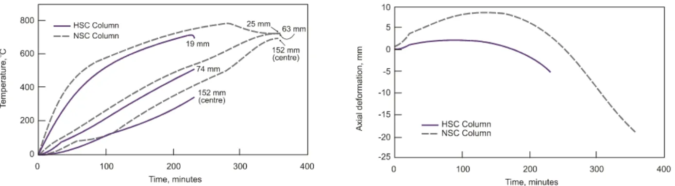
Typical results from fire-resistance tests involving NSC and HSC columns are shown in Figures 1 and 2. Except for the concrete strength, the NSC and HSC columns had similar characteristics and were subjected to comparable load levels. The columns were of square cross section (305 mm x 305 mm) and 3810 mm long with the 28 day compressive strength of the NSC column being 34 MPa as opposed to 83 MPa for the HSC column. The variation of cross-sectional temperatures for NSC and HSC columns is shown in Figure 1 as a function of exposure time. These temperatures, measured during the fire tests, are shown for various depths from the surface along the centreline and at mid-height of the column. It can be seen from Figure 1 that the temperatures in the HSC column are generally lower than the corresponding temperatures in the NSC column throughout the fire exposure. This variation can be attributed in part to the variation in thermal and mechanical properties of the two concretes and to the higher compactness (lower porosity) of HSC. The low porosity of HSC affects the rate of increase of temperature in HSC until the cracks widen and spalling of the concrete occurs. Large cracks occurred in the HSC column only after approximately 3 hours of fire exposure.
Figure 1 Temperature distribution at various Figure 2 Axial deformation for HSC and depths in NSC and HSC columns NSC columns
The variation of axial deformation with time is compared for NSC and HSC columns in Figure 2. It can be seen from the figure that the behaviour of the HSC column is different from that of the NSC column. Both the NSC and HSC columns expand until the reinforcement yields and then contract leading to failure. The initial deformation of the column is mainly due to the thermal expansion of both concrete and steel. In the case of the HSC column, the deformation is significantly lower than that of the NSC column. This can be attributed partly to the lower thermal expansion of HSC and the slower rise of temperature in the HSC column during the initial stages due to the high compactness of HSC. When the steel reinforcement in the column gradually yields because of increasing temperatures, the column contracts.
When the steel yields, the concrete carries a progressively increasing portion of the load. The strength of the concrete also decreases with time and, ultimately, when the column can no longer support the load, failure occurs. In this stage, the behaviour of column is dependent on the strength of the concrete. There is significant contraction in the NSC column leading to gradual ductile failure. The contraction in the HSC column is much lower. This can be attributed to the fact that HSC becomes brittle at elevated temperatures and the strain attained at any stress level is lower than that attained in NSC for any given temperature. This is especially applicable for the descending portion of the stress-strain curve of HSC at elevated temperatures.
Based on the observations during and after fire resistance tests, while there was no spalling in the NSC column, there was spalling at the corners towards later stages of fire, prior to failure occurred in the HSC column. Spalling, which results in the loss of concrete during a fire, exposes deeper layers of concrete to fire temperatures, thereby increasing the rate of transmission of heat to the inner layers of the structure, including the reinforcement. The rebars in HSC columns were fully exposed to fire during the later stages of fire. This spalling is due to the low permeability in HSC [1,10] and has also been observed in previous studies on typical HSC structural members under laboratory and real fire conditions [1,2,3]. Figure 3 illustrates spalling in NSC and HSC columns after fire resistance tests and it can be seen that spalling in HSC column is higher than that for NSC column. However, it should be noted that the spalling was not significant in this HSC column, and this is mainly due to the provision of improved tie configuration (further explained in later section) that helps minimise spalling (14).
In these tests, the time to reach failure is defined as the fire resistance of the column. For the NSC column, the fire resistance is approximately 366 minutes while, for the HSC column, it is approximately 225 minutes. The decreased fire resistance for the HSC column, as compared to the NSC column, can be attributed to faster degradation of thermal and mechanical properties of HSC.
Numerical Studies
The main objectives of the experimental studies were to generate fire resistance data for immediate use by the construction industry, and to provide information for the development of general methods for calculating the fire resistance of HSC columns. Mathematical models were developed for predicting the fire behaviour of HSC columns [15.16]. The steps, associated with the development of the models, involved the calculation of the fire temperatures and the temperatures, deformations and strength of the concrete-steel composite assembly. A simplified approach was used to account for spalling under fire conditions.
The models can take into account the influence of the various parameters that determine the fire performance of HSC columns and can trace the response of an HSC column from the initial pre-loading stage to collapse, due to fire. The validity of the model has been established by comparing the results from the models to test data [15,16]. The model is being used to carry out parametric studies to generate data on the fire resistance of HSC columns. The results of the
preliminary parametric studies indicate that the fire resistance and the extent of spalling in HSC columns is a function of a number of parameters including its size, the concrete strength, the load intensity, tie configuration, type of aggregate and type of fire intensity.
(a) NSC Column (b) HSC Column
Figure 3 Comparison of Spalling in NSC and HSC Columns after Fire Resistance tests [3]
FACTORS GOVERNING FIRE PERFORMANCE
Data from the studies carried out at NRCC, as well as a number of organizations world-wide, show that fire performance of HSC, in general, and spalling in particular, is complex and is affected by a number of factors. Based on the analysis of model predictions, test data and the visual observations made during and after the fire tests, some of the factors that influence the fire endurance of HSC columns are briefly discussed below.
Concrete Strength
Results from a number of fire resistance tests show that high fire endurance (three hours or more) can be obtained for HSC columns even under full service loads. However a comparison of the fire endurance of HSC columns with that of NSC columns [11, 12] indicate that the HSC columns have the lower fire endurance of the two. However, HSC columns must be reinforced with increased levels of confinement reinforcement (as prescribed in CSA-A23.3 [8]) over that used in NSC columns if the same fire endurance ratings are to be achieved by both types of columns. The spalling performance of an NSC column is compared to an HSC column in Figure 3 as observed from full-scale fire tests on loaded columns [12]. It can be seen that the spalling is quite significant in the HSC columns.
While it is hard to specify the exact strength range, based on the available information, concrete strengths higher than 70 MPa are more susceptible to spalling and may result in lower fire resistance.
Concrete Moisture Content
The moisture content, expressed in terms of relative humidity (RH), influences the extent of spalling. Higher RH levels lead to greater spalling. Fire-resistance tests on full-scale HSC columns have shown that significant spalling occurs when the RH is higher than 80%. The time required to attain an acceptable RH level (below 75%) in HSC structural members is longer than that required for NSC structural members because of the low permeability of HSC. In some cases, such as in offshore structures, RH levels can remain high throughout the life of the structure and should therefore be accounted for in the design.
Concrete Density
The effect of concrete density was studied by means of fire tests on normal-density (made with normal-weight aggregate) and lightweight (made with lightweight aggregate) HSC blocks [17]. The extent of spalling was found to be much greater when lightweight aggregate is used. This is mainly because the lightweight aggregate contains more free moisture, which creates higher vapour pressure under fire exposures.
Fire Intensity
The spalling of HSC is much more severe in fires characterized by fast heating rates or high fire intensities [4,5]. Hydrocarbon fires pose a severe threat in this regard. When HSC is to be used in facilities where hydrocarbon fuels are present, such as offshore drilling structures and highway tunnels, the probable occurrence of spalling in the presence of fire should be considered in the design.
A review of the literature shows that the risk of explosive thermal spalling increases with specimen size. This is due to the fact that specimen size is directly related to heat and moisture transport through the structure, as well as the capacity of larger structures to store more energy. Therefore, careful consideration must be given to the size of specimens when evaluating the spalling problem; fire tests are often conducted on small-scale specimens, which can give misleading results. However, when spalling mitigation measures (such as the one given in the following section) are incorporated, the risk of explosive spalling decreases and fire resistance increases with the size of the members. Also, similar cover thickness to reinforcement, as in the case for NSC columns, based on structural (corrosion) considerations should be provided for HSC columns.
Lateral Reinforcement
Results from fire resistance studies clearly show that the layout of ties and confinement of columns have an influence on the fire performance of HSC columns. Higher fire endurance in HSC columns can be achieved by providing improved tie configuration (provision of bent ties at
135° back into the core of the column and increased lateral reinforcement) and with closer tie
spacing (at 0.75 times that required for NSC columns). Figure 4 shows a conventional and modified tie configuration for HSC column. The provision of cross ties also improves fire endurance [10,14]. These provisions also minimise the extent of spalling in HSC columns.
Figures 5 show photographs of the column specimens, with conventional and improved tie configuration, after the fire resistance tests. The extent of spalling in columns, with bent ties configuration, was relatively less compared to that in columns without bent tie configuration. Columns containing only 90º ties would typically lose a significant portion of the columns section upon failure. Columns using 135º ties would exhibit the classic pyramid compression failure section with the failed section being confined locally to one or two tie spacing.
Fibre Reinforcement
Studies show that the addition of polypropylene fibers minimizes spalling in HSC members under fire conditions [6]. One of the most accepted theories on this is that by melting at a
relatively low temperature of 170°C, the polypropylene fibres create "channels" for the steam
pressure within the concrete to escape, thus preventing the small "explosions" that cause spalling. The amount of polypropylene fibres needed to minimize spalling is about 0.1 to 0.15% (by volume) [5,12,17]. Addition of steel fibres enhances tensile strength and reduces spalling [12,17].
Conventional Tie Configuration Modified Tie Configuration
Figure 5 Comparison of Spalling in HSC Columns after Fire Resistance tests [11] Load Intensity and Type
The type of load and its intensity have significant influence on spalling and the resulting fire resistance. The fire endurance of a column increases with a decreasing load. Higher load intensity leads to lower fire resistance, since the loss of strength with a rise in temperature is greater for HSC than for NSC. A loaded HSC structural member is susceptible to higher spalling than an unloaded member. This is specially true in columns with conventional tie configuration and subjected to loads greater than service loads. This occurs because a loaded structural member is subjected to stresses due to load in addition to the pore pressure generated by steam.
Further, the extent of spalling is higher if the load is of an eccentric (or bending) type since this will induce additional tensile stresses.
Type of Aggregate
Of the two commonly used aggregates, carbonate aggregate (predominantly limestone) provides higher fire resistance and better spalling resistance in concrete than does siliceous aggregate (predominantly quartz). This is mainly because carbonate aggregate has a substantially higher heat capacity (specific heat), which is beneficial in preventing spalling. This increase in specific heat is likely caused by the dissociation of the dolomite in the carbonate concrete. In general the fire endurance of HSC columns made with carbonate aggregate concrete is 10% higher than HSC columns made with siliceous aggregate concrete [10,11,12].
GUIDELINES FOR ENHANCING FIRE PERFORMANCE
High-strength concrete is a high-performing material that offers a number of advantages. In recent years significant research has been undertaken to study the fire behaviour of HSC columns and to quantify the factors influencing their spalling and fire endurance. However, to-date there are no specific guidelines in codes and standards for the fire resistance design of HSC structural members.
By adopting appropriate measures, spalling in HSC can be minimised and the fire endurance can be enhanced even for concrete strength as high as 110 MPa. Based on these detailed studies at NRCC and elsewhere, the following are some of the preliminary guidelines that can be implemented for enhancing fire performance:
• The size of structural members has an influence on fire endurance and the provisions in
current standards specify minimum cross-sectional dimensions for NSC columns. The recommended minimum dimensions for achieving fire endurance ratings in HSC columns (both square and circular) are:
1 hour 12"
1-1/2 hour 14"
2 hour 16"
3 hours or more 20"
These dimensions are relatively higher than those required for NSC columns.
• Fire endurance and the extent of spalling is influenced by the tie configuration adopted for
the column. Installation of bent ties (when the ties are bent at 135o into the concrete core)
helps to minimise spalling and increases fire endurance (Figure 4). Provision of cross ties also improves fire resistance.
• Addition of polypropylene fibres, about 0.1 to 0.15% by volume, to the mix reduces spalling.
• Addition of steel fibres enhances tensile strength and reduces spalling [12,17].
• Use of carbonate aggregate, instead of siliceous aggregate, reduces spalling and enhances fire
• The spalling of HSC is much more severe in fires characterized by fast heating rates or high fire intensities. When HSC is to be used in facilities where hydrocarbon fuels are present, such as offshore drilling structures and highway tunnels, the probable occurrence of spalling should be considered in the design. Addition of polypropylene fibres, about 0.1 to 0.15% by volume, to the concrete mix significantly reduces spalling.
• Provision of sufficient concrete cover thickness to reinforcement as specified in standards
based on structural (corrosion) considerations.
SUMMARY
High strength concrete is a high-performing material and offers a number of benefits over normal strength concrete. However, there is a concern on the occurrence of spalling and lower fire endurance of HSC (as compared to NSC). The type of aggregate, concrete strength, concrete density, load intensity, fire intensity and tie configuration have an influence on the fire performance (both spalling and fire endurance) of HSC columns. By adopting design guidelines, such as the addition of fibres and an improved tie configuration, spalling in HSC members can be minimized to a significant extent and fire endurance can be enhanced. The polypropylene fibers are much more effective in minimising spalling in HSC under hydrocarbon fires.
REFERENCES
1. Phan, L.T. "Fire Performance of High-Strength Concrete: A Report of the State-of-the-Art", National Institute of Standards and Technology, Gaithersburg, MD, pp. 105, 1996.
2. Diederichs, U.; Jumppanen, U.M., Schneider, U. "High Temperature Properties and Spalling
Behaviour of HSC", Proceedings of 4th Weimar Workshop on HPC, HAB Weimar, Germany,
pp. 219-235, 1995.
3. Kodur, V.R., Sultan, M.A. "Structural behaviour of high strength concrete columns exposed to fire" Proceedings: International Symposium on High Performance and Reactive Powder Concrete, Vol. 4, 217-232, Sherbrooke, Quebec, 1998.
4. Danielsen, Ulf. "Marine Concrete Structures Exposed to Hydrocarbon Fires", Report, SINTEF – The Norwegian Fire Research Institute, pp. 56-76, 1997.
5. Bilodeau, A., Malhotra, V.M. and Hoff, G.C. "Hydrocarbon Fire Resistance of High Strength Normal Weight and Light Weight Concrete Incorporating Polypropylene Fibres", International Symposium on High Performance and Reactive Powder Concrete, Sherbrooke, QC, pp. 271-296, 1998.
6. National Research Council of Canada, National Building Code of Canada, Ottawa, ON, 1995. 7. ACI Committee 318, "Building Code Requirements for Reinforced Concrete" (ACI 318-95),
American Concrete Institute, Detroit, 1995.
8. Canadian Standards Association, Code for the Design of Concrete Structures for Buildings. CAN3-A23.3-M94, Rexdale, ON, 1994.
9. ACI Committee 216, "Standard Method for Determining Fire Resistance of Concrete and Masonry Construction Assemblies", American Concrete Institute, Detroit, 1997.
10. Kodur, V.K.R. "Spalling in HSC Exposed to Fire: Concerns, Causes, Critical parameters and Cures", Proceedings, ASCE Structures Congress, Philadelphia, PA, 2000.
11. Kodur, V.K.R. and McGrath, R., Performance of High Strength Concrete Columns Under Severe Fire Conditions. Proceedings Third International Conference on Concrete Under Severe Conditions, Vancouver, BC, Canada, pp. 254-268, 2001.
12. Kodur V.K.R.; Cheng F.P.; Wang T.C. "Effect of strength and fiber reinforcement on the fire resistance of high strength concrete columns", ASCE Journal of Structural Engineering, 129(2), pp. 253-259, 2003.
13. American Society for Testing and Materials, Standard Methods of Fire Endurance Tests of Building Construction and Materials. ASTM E119-00, Philadelphia, PA, 2000.
14. Kodur, V.R7.; McGrath, R.C. "Fire endurance of high strength concrete columns" Fire Technology – Special Issue, Vol. 39: No. 1, 2003
15. Kodur, V.R.; Wang, T.C.; Cheng, F.P.; Sultan, M.A. "A Model for evaluating the fire resistance of high performance concrete columns" Proceedings (in press) 7th International Association of Fire Safety Science Symposium (Worcester, MA., U.S.A.), pp. 1-13, 2002. 16. Kodur, V. R.; Wang T.C.; Cheng, F.P. "Predicting the fire resistance behaviour of high
strength concrete columns" (in press), Cement and Concrete Composites Journal, pp. 22, 2003
17. Kodur, V.R. "Fibre-Reinforced Concrete for Enhancing the Structural Fire Resistance of Columns" Fibre- Structural Applications of Fibre-Reinforced Concrete, ACI SP-182, pp. 215-234, 1999.
![Figure 3 Comparison of Spalling in NSC and HSC Columns after Fire Resistance tests [3]](https://thumb-eu.123doks.com/thumbv2/123doknet/14193606.478573/7.918.112.795.235.720/figure-comparison-spalling-nsc-hsc-columns-resistance-tests.webp)
![Figure 5 Comparison of Spalling in HSC Columns after Fire Resistance tests [11]](https://thumb-eu.123doks.com/thumbv2/123doknet/14193606.478573/10.918.122.807.335.817/figure-comparison-spalling-hsc-columns-resistance-tests.webp)
