Publisher’s version / Version de l'éditeur:
ASTM Special Technical Publication, 361, pp. 192-211, 1965-05-01
READ THESE TERMS AND CONDITIONS CAREFULLY BEFORE USING THIS WEBSITE. https://nrc-publications.canada.ca/eng/copyright
Vous avez des questions? Nous pouvons vous aider. Pour communiquer directement avec un auteur, consultez la première page de la revue dans laquelle son article a été publié afin de trouver ses coordonnées. Si vous n’arrivez pas à les repérer, communiquez avec nous à [email protected].
Questions? Contact the NRC Publications Archive team at
[email protected]. If you wish to email the authors directly, please see the first page of the publication for their contact information.
NRC Publications Archive
Archives des publications du CNRC
This publication could be one of several versions: author’s original, accepted manuscript or the publisher’s version. / La version de cette publication peut être l’une des suivantes : la version prépublication de l’auteur, la version acceptée du manuscrit ou la version de l’éditeur.
For the publisher’s version, please access the DOI link below./ Pour consulter la version de l’éditeur, utilisez le lien DOI ci-dessous.
https://doi.org/10.1520/STP29995S
Access and use of this website and the material on it are subject to the Terms and Conditions set forth at
Pore pressures within soil specimens in triaxial compression
Crawford, C. B.
https://publications-cnrc.canada.ca/fra/droits
L’accès à ce site Web et l’utilisation de son contenu sont assujettis aux conditions présentées dans le site LISEZ CES CONDITIONS ATTENTIVEMENT AVANT D’UTILISER CE SITE WEB.
NRC Publications Record / Notice d'Archives des publications de CNRC:
https://nrc-publications.canada.ca/eng/view/object/?id=1b60da57-bedc-4ab2-9ab0-495f9932271d https://publications-cnrc.canada.ca/fra/voir/objet/?id=1b60da57-bedc-4ab2-9ab0-495f9932271dL'INTERIEUR U N E COMPRESSION 1 8 i n t 6 r i e u r de s p pendant l a conso dans l e c a s d ' e s s a i s permettant de m e s f h r i e u r e du sions effective
rluthorizcd Rcprint lrom thc Copyrigl~tcd Lnborntory Shear Testing of Soils
Sbccinl I'rcl,,ricol Pirblicnlir~~c 3 4 1
- A ~ ~ ~ V L E D
1 II"11>111~Zmcrican Socicty lor ,,..,.,!.,. XI by the
Testing and hIaterials
PORE PIiESSEIiES W I T H I N SOIL S P E C I M E S S I N T R I A X I A L COi\llPRESSION
BY C.UZL B. CK-LWFORD,' Psnl. hllemb. ASTM
SYNOPSIS
Pore pressure nleasurements at the base and within undisturbecl specilnens oi a sensitive clay during coilsolidatio~l and shear indicate that ineinbraile leakage is not serious for orclinary tests. A technique for measuring pressures ~vithin the speciinen is describecl. I11 the soil tested, greater pore pressures were developed at the lower end of the specinlen than in the center and this \vas attributed to end restraint. Because failure occurs near the bottom of the specimens, the pressure illeasured at the base plate is considerecl to be satis-
a1 ure. factory ior the computatioil of effective stresses at f 'I
T h e effective stresses in a saturated THE SOIL
soil speciinen during shear tests in the ~ h , tests ,ere lllade on specilllens laboratory are colll~utecl subtracting trilllllled frolll a n unclisturbecl block the nleasured pore water pressure from salllple of ~~d~ ,-lay which had been the stresses. the refined obtained a t a depth of 33 f t froin a sillall equipnlent now available it is possible tunnel ill the city of
ottawa.
~h~ soil to nleasure total stresses with reasonable has a llatural water colltellt of about 58accuracy. Pore pressure observations per cent, a liquid lilllit Of 53 per cent, and interpretation are less reliable for and a plastic lilllit Of 25 per ~h~ a t least two reasons: First, the pore pore water colltaills about 2 per liter pressure inay vary throughout the speci- of salt, alld the sensitivity is about j0.
men, and the point a t which it is meas- A series of triasial colllpression tests ured may not be representative of the all adjacent block of soil frolll conditions in the shearing zone. Second, this tunnel have beell described (I)." pore pressures nlay be incorrectly at-
tributed to the shearing action when they R'IE~IBRXNE LE.-\K.-\GE are in fact due to leakage froill the cell peculiarities in triasial test results or to a secondary consolidation effect. have often been attributed to leakage of This Paper describes tests ''lade at water through the rubber membrane. the Division of Building Research of the 1, so,e cases where the ,,lelllbrane is Xational Research Council to assess the dalllaged during illstallation or where reliability of norillal pore pressure ob- proper are not made a t the a servations during triaxial loading of substantial leakage lllay be revealed undisturbed specinlens of clay. by routine observations, but for ordi-
1 I-Iead, Soil >Iech;uiics Sectio11, Divisioti of -
Building Research, Nntioiinl Iteseal.cl1 Cou~icil, Tlle 12oldf:lce nulnbers in ~nrerltheses refer
Ottawa, Canada. to tlle list of references appe~icled t o this paper.
nary short-term tests, leakage through the membrane itself is not thought to be serious. This has been the writer's esperience and it agrees with the views of Casagrande and Hirschfeld (2).
Soine simple checks have been made which tend to confirm that ineinbrane leakage is normally small. Several thin rubber ineinbranes (Ranlses type, 0.005 cin thick) were subjected to osmotic
applied to the end caps under the mem- brane. Doubling the inenlbrane had no apparent effect.
A further assessment of membrane leakage was made by consolidating a specimen for four days with a cell pres- sure of 4.5 kg/cm2 and a back pressure on the pore water of 0.5 kg/cin2 and then closing the drainage and nleasuring the pressure a t the base plate for an pressure by filling them with salt soltl- additional day. T h e pore pressure a t the tion and imnlersing them in distilled base of this specimen (96-4-19, Table 1) water. Even a t a salt concentration of 150 increased from 0.5 to 0.8 kg/cm2 in 8 g per liter the leakage through a mem- hr and then remained approximately brane was only about 0.1 g per day. A constant overnight. Considering that wet cup vapor permeability test, such p a r t of the increase is due to a secondary
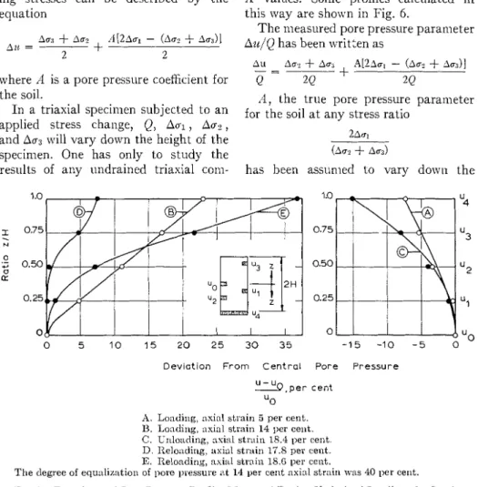
TABLE 1-TEST RESULTS.
Natural Effective
Specimen
($;%\
WaterC$,"g:-
L ~ ~ ~Watcr Ex- , f Change Difference, Differencepressure, T ~lir ~ pelled, cm3 ~ , in m t , g c r n ~ per hr, cm3 kg/crn'
as is applied to building materials, caused a flow through a similar area of mem- brane of only about 0.2 g per day. Leak- age under triaxial test conditions would probably be much smaller than in these special tests.
A few tests have been made in which the triaxial equipment has been as- sembled in the routine manner but with a lucite cylinder in place of the soil specimen. These have included single and double inembranes with a layer of vaseline between, and the end caps have been used perfectly clean or sineared with grease. I n all these tests the rate of leakage was less than 0.2 g per day a t cell pressures of 4 kg/cm2. Minimull1 leakage was obtained when grease was
consolidation effect, the membrane leakage does not appear to be significant in this case.
This specimen was then axially loaded to 0.9 k g / c m V n 8 lnin and the strain was held constant a t 0.14 per cent for 5
hr. During this time the axial stress had to be reduced to 0.48 kg/cm2 to prevent further axial strain, while the pore pres- sure increased froin 1.12 to 1.29 kg/cm2. An identical speciinen (96-4-20) per- formed similarly. Previous work (1)
showed a simple relationship between pore pressure and axial strain a t con- stant axial stress, but these present observations indicate that the pore pressure will increase even though axial strain for the entire specimen is held
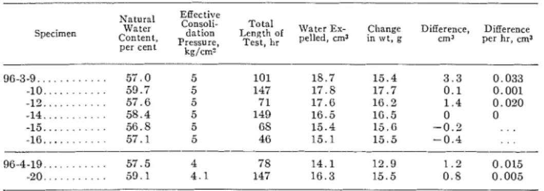
All tests were carried out in a pr::- cision triaxial cell with rotating bushing as described by Andresen aild Sinlolls
(3). T h e undisturbecl clay specimens, measuring 8 cm in height and 10 sq clll in area, were enclosecl in a single rubber membrane. Observations of rate of consolidation showed no appreciable difference whether or not filter-paper side drains were used, so thcy were not used in the tests reported here.
Poye Pressz~re h'eedles:
A number of variations were tried before a satisfactory technique was de- veloped for measuring pore pressures FIG. 1-Test Specimen with Needles Installed
Sho\ving No-Elow Indicators. within the specimen. This rvas achieved Tap -24 UNF
l o r i l ' x
i"
Brass Tube Fitting w i t h Inset!Tu '0' R ~ n o D r i l l $"'
--
.
j/; I 3 v i Back Side i ~ i l t h Etch hlar k Heavyi'' f t c h on Back I MATER I AL: Acrylic Plaslic Thread <-24 UNF IAr~nealedl C u t for:" '0' RingFIG. 2-Pore Pressure Null Indicator.
constant. This is attributed to structural by inserting into the soil medical hypo- collapse under the all-round eflective derinic needles (0.12 cin OD). T h e pore stresses: a secondary consolidation effect. pressure systenl Ivas prepared by drawing T h e axial strain under constant stress, de-aired water through it. T h e water in which was previously observed, inay the needle was then quick-frozen with result from this breakdo\vn of structure dry ice to prevent the entry of soil dur- rather than cause it. ing insertion. Two needles were installed
in each specimen, one extending along the axis to the middle of the speciillen froill the top cap and one extending horizontally to the center of the speci- men, 2 cm above the bottoin as shown in Fig. 1.
Efforts were illacle to seal the hole through the nlembrane using liquid lates, but the easiest and inost reliable seal \vas obtained using a n ordinary clear rubber celllent called "Kleen Stik."
in which a slug of inercury could be in- serted illto the pore pressure line lead- ing from the cell to the pump in order t o indicate flov.7 (Fig. 2). I t could b e inounted with a ininiillu~n of pressure line and coilnectioils between the mercury slug and the cell. During flush- ing of the pore pressure system the slug of mercury rests in a recess in front of the screw piston. When t h e assembly is completed the device is tilted and the
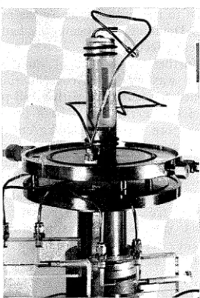
FIG. 3-Relationship of Volume Change and Pore Pressure to Time After Beginning of Drainage.
Owing to their relatively sillall sphere of influence, the pore pressure needles require a much more rigid system than is necessary to measure pressures a t the base plate. The ordinary U-tube no- flow indicator and associated connections and copper lines did not seeill to perforiu adequately when used with the needles. Response to pressure changes was slower than desired. I n spite of great care, unexplained illoveinents occurred in the mercury colunlns even when valves were closed and pressures were constant.
A simple device was therefore built,
0 2 I " 0 "7
--.
0 Y - 2-
W R 3 cn cn 3 % a W R 0 4 " Z - w 0 5 5 I U 0 5s
,
0 1 0 -1) W 05
I 5 I u W I 3 2 0 0 > 2 5piston is given a slight turn to force the nlercury to the center of the horizontal capillary. When pressures are generated a t the needle they are coillpensatecl by a manual pressure system leading t o the opposite end of the mercury. A
test set-up showing the needles \vith two of the no-flow indicators is illustrated in Fig. 1. 1 0 - 2 l o - ' 10 l o 2 l o 3 1 0 T I M E , M I N U T E S 0-.- I I S P E C I M E N S Y M B O L S 9 6 - 3 - 12 • -
+
x - " 0 " RING - - - PRESSURES NO. 2 - . , -+ - D R A I N -4
A V - L O C A T I O N OF N E E D L E S I N S P E C I M E N I I I I TEST RESULTSOf the several tests made with internal pore pressure measurements, six were clone in a n identical illailner with a single membrane, no side drains, and with pore pressure needles installed as
sho~vn in Fig. 3. These sis tests were free of serious leaks; the pore pressure ecluipr~~ent functioned satisfactorily, and the results were similar in each case. The water expelled into the buret during consolidation is compared in Table 1 with the change in weight during the test.
Several factors operate to cause dis- agreement between the observed voluine change and weight change during a test. As inentioiled previously, leakage
special precautions were taken, every joint and valve is a potential leak which, due to evaporation, may not be ap- parent. I n nlore recent tests the "Klinger" valves have been replaced by "circle-seal" valves, and this seems to have improved the results. These observations indicate the order of pos- sible inaccuracies in the measurements. Two of the tests in which the observa- tions are rnost complete have been
4 I I I I I 4 \ I N C R E A S E S T R A I N R A T E T O 2 . 5 %/HOUR S P E C I M E N 9 6 - 3 - 1 2
r
0 I 2 3 0 I 2 3 S T R A I N , %FIG. 4-Variation of Pore Pressure and Stress with Strain.
through the ineinbrane itself is not thought to be especially serious. I n two cases (specimens 9 and 12), some leakage around the end caps may have occurred. T h e absorption of water during the time taken to dismantle the apparatus in- creases the weight measured a t the end of test and decreases the computed change in weight. Therefore, the differ- ence between the volume and weight nleasureinents nlay be a little less than indicated in Table 1. Negative differ- ences must be due to leakage fro111 the volume nleasuring system. Although
selected to illustrate the test results. I n each case the cell pressure and the pres- sure in the pore pressure system were advanced siillultaneo~isly to 6 kg/cm2. Then the drain was opened but a back pressure of 1 kg/cm2 was maintained during coilsolidatioil to mininlize the effect of air in the system. T h e response of the pore pressure through the needles, after the drainage valve was opened to the base plate, is shown in Fig. 3, to- gether with the per cent volunle change as indicated by the expelled pore water. These observations are in line with
expectations and indicate that the pore pressure devices are operating satisfac- torily.
Follo~ving consolidation, the speci- inens were axially strained without drainage a t about
%
per cent per hr, while pore pressures were measured a t the needles and a t the base plate. Speci- inen 12 was strained for 24 hr, but when specimen 14 had reached nearly 1 per cent axial strain, the rate was increased to about 2% per cent per hr. The meas-ured vertical stress and pore pressures for the two tests are show11 in Fig. 4. T h e performance of specinlen 96-3-12 is generally representative of all of the test results, except that the pore pres- sure response to axial loading was slightly inore than for other tests. At a strain of 0.2 per cent, approxinlately one half of the illtiinate deviator stress was acting on the specimen, and pore pressure parameter /I, which is the ratio of pore pressure to deviator stress, was about 0.9 according to the base plate measure- ment (4). I n lnost tests strained a t 0.5 per cent per hr, the value of A a t half failure load was about 0.5 to 0.6, and in tests strained a t faster rates it was even less (5). T h e most important ob- servation is that a t a particular strain the pore pressures in the lower quarter of the specimen are fairly uniform, but higher than pore pressures near the center. At lo1v strains the difference is of greater significance than a t failure.
Speciinen 96-3-14 was representative of other tests until the rate of strain was increased froin 0.5 to 2.5 per cent per hr. T h e increased rate of strain appeared to reduce the rate of pore pressure increase and caused a noticeable increase in shearing resistance. The pore pressure gradient froin center to base plate was also increased by the more rapid loading.
T h e necessity of assessing shearing resistance in terms of effective stresses
has einphasizecl the need for reliable measurements and a better understand- ing of pore pressure developinent during testing. A special "Pore Pressure and Suction in Soil Conference" was held in London in 1960. Later in the same year the "Research Coilfereilce on Shear Strength of Cohesive Soils" spoilsored by the American Society for Civil Engi- neers featured many references to pore pressure variatioils and difficulties of measurement.
Bishop et a1 (6) noted that "pore pressure gradients may arise owing to nonuniformity of stress during the shear stage due to end restraint and a tendency to narrow zone failure which appears to be characteristic of soine samples." Henkel (7) coilfirlned the occurrence of "localizecl thin failure zones" in un- disturbed specimens, and he recom- mended slower rates of testing than for reinolded material. Marsal and Resines (8) shared the concern for errors due to friction a t the end plates. Shockley and Ahlvin (9) provided evidence of signifi- cant nonuniformity through a triaxial specinlen which could have a great influeilce on pore pressures.
Whitmail (lo) reported extensive stud- ies on undisturbed Bostoll clay and noted a tendency for end pore pressures to lag behind center pore pressures a t the faster rates of strain. This cor- related with higher water contents near the ends of the speciinen after the test. Bishop et a1 (6) in their closing discussion reported the pore pressure a t the base of conlpacted speciineils to be greater than a t mid-height. This was attributed t o the influence of end restraint. Gibbs e t a1 (11) described test results on compacted clay in which pore pressures measured in the center and a t the ends were identi- cal. These variations in observed pore pressures illustrate the uncertainties associated with any rigorous interpre- tation of their significance.
eclually confusing. They show that even a t the relatively slow rate of strain (0.5 per cent per hr) the pore pressure in the center of the speciinen lags behind the pore pressure a t the base by as much as 0.5 kg/cln' but once the masimtml deviator stress is reached the pressures are aliuost equalized. Previously pub- lished tests (1) on soil fro111 an adjacent block sainple showed, however, that the soil froin the failure plane is always substantially drier than that a t the ends. This does not correlate with the pore pressure n~easurements, although it should be noted that the water content observations mere made on specimens that had been strained well past failure when pore Fressure gradients appear to be insignificant. In addition, the top pore pressure needle was located a t the geometric center of the specimen, but the failure plane invariably passed through the lower half of the specimen. A inore conlplete discussion of failure planes in a sinlilar soil has been presented (12).
I t seeins reasonable, therefore, to assuine that the pore pressure on the failure plane and that a t the base plate are alnlost equal. I t follotvs fro111 Bishop's explanation that the pore pressures are induced prinlarily by localized stresses due to end restraint, and the reduction in ell'ective stress causes the failure plane to develop near the base. This is con- sistent with the fact t h a t the porous base plate offers inore restraint than does the acrylic plastic top cap.
seriously alfect pore pressure measure- ments.
2. In sensitive undisturbed Leda clay, pore pressures can develop under con- stant stress or even when average stress is decreasing. This is attributed to a secondary consolidation effect in which the collapsing soil structure transfers some of the applied stress to the pore \va ter
.
3. Hypoderinic needles inserted in the test specilllens appear to provide satis- factory pore pressure pick-ups provided a sinall volume pore pressure systenl with few opportunities for leaks is used. 4. Under the initial slow axial loading the test specimen develops higher pore pressures a t its lower end than a t the geometric center. After failure the pore pressures tend to equalize.
5. Increasing the rate of strain during a test reduces the pore pressure slightly and causes increased shearing resistance. 6. The higher pore pressure a t the base is attributed to disturbance caused by end restraint, and the resulting decrease in effective stresses are thought to be the reason for the fact that failures occur near the base.
7. Pore pressures measured a t the base plate are thought to represent satisfactorily the pressures on the failure plane, but owing to the variety of experiences reported in the literature, further research on this problem is necessary.
C O ~ C L U S I O ~ S T h e interest and careful assistance of D. C. MacMillan in carrying out the On the basis of these tests the follow- tests are gratefully acknowledged. The ing conclusions are drawn: paper is published with the approval of
1. I n carefully prepared short-term the Director of the Division of Building triaxial tests, membrane leakage does not Research, National Research Council.
(1) C. B. Cralvforcl, "The Influence of Strain (2) A. Casagrande and R. C. Hirschfeld, on Shearing Resistance of Sensitive Clay," "Stress-Delormatio~~ and Strength Char-
Proceeditzgs, Am. Soc. Testing Mats., Vol. acteristics of a Clay Compacted to a Con- 61, 1961, pp. 1250-1276. stant Dry Unit Weight," Proceedings, Am.
Soc. Civil Engrs., Research Conference on Shear Strength of Cohesive Soils, Boulder, Colo., 1960, pp. 359-417.
(3) A. Andresen and N. E. Simons, "Korwegian Triasial Equipment ant1 Technlcjue," I'ro-
ceediwgs, Am. Soc. Civil Engrs., Research
Conference on Shear Strength of Cohesive Soils, Bouldcr, Colo., 1960, pp. 695-709. (4) A. W. Skempton, "The Pore Pressure Co-
efficients A ancl B," Gkotecl~nique, Vol. 4, No. 4, 1954, pp. 113-147.
(5) C. B. Cra\rford, "The Influence of Rate of Strain on Effective Stresses in Sensitive Clay," Soils, A S T I I I S T P 254, Am. Soc.
Testing Mats., 1959, pp. 36-61.
(6) A. W. Bishop, I. Alpan, G E. Blight, ancl 13. Donald, "Factors Controlling the Strength of Partly Saturatctl Cohesive Soils," Proceedings, Am. Soc. Civil Engrs., Research Conference on Shear Strength of Cohesive Soils, Boulder, Colo., 1960, pp. 503-532.
(7) D . J. Henkel, "The Shear Strength of Saturated Remoulded Clays," Proceedings, Am. Soc. Civil Engrs., Research Confer- ence on Shear Strength of Cohesive Soils, Boulder, Colo., 1960, pp. 533-545.
(8) R. J. i\.Iarsal and J. S. Resines, "Pore Pres- sure and Volumetric Measurements in Tri- axial Compression Tests," Proceedilzgs, Am. Soc. Civil Engrs. Research Conference on Shear Strength of Cohesive Soils, Boulder Colo., 1960, pp. 965-983.
(9) W. G. Shockley and R. G. Ahlvin, "Kon- uniform Conclitions in Triaxial Test Speci- mens," Proceedi~zgs, Am. Soc. Civil Engrs Research Conference on Shear Strength ol Cohesive Soils, Boulder, Colo., 1960, p p 341-357.
(10) R. V. Whitman, "Some Considerations and Data Regarding the Shear Strength of Claps," Proceeditzgs, Am. Soc. Civil Engrs. Research Conference on Shear Strength of Cohesive Soils, Boulder, Colo., 1960, pp. 581-614.
(11) H. J. Gibbs, J. W. Hill, W. G. Holtz, and F. C. Walker, "Shear Strength of Cohesive Soils," Proceeditzgs, Am. Soc. Civil Engrs. Research Conference on Shear Strength of Cohesive Soils, Boulder, Colo., 1960, pp. 33-162.
(12) C. B. Cralvford, "Cohesion in an Undis- turbecl Sensitive Clay," Gkotecl~nigt~e, Vol. 13, No. 2, June, 1963, pp. 132-146.
DISCUSSION
G. E. B ~ r G ~ ~ l - T h r e e of the papers in this s 4 have concerned them-
selves wholly or in part with problems arising froin the presence of nonuniforin pore pressures within a triaxial speci- nlen during testing. This is therefore a n opportune time to present some addi- tional data on this subject.
Profiles of Pore P~essztre:
Mr. Crawford has drawn attention to the number of different and apparently conflicting observations on pore pressure profiles published in the proceedings of the 1960 conference a t Boulder. I t was reported by various workers that the University of the \Vitwatersraud, Johannes burg, South Africa.
C. B. Crawford, "I'ore Pressures Iliitllin Soil Specinlens in Triasial Comgression" (see 1). 192). N. E. Simons, "The Influence of Labora- tory Stress Path on Trinxial Test Results" (see
13. 370).
" G. E. Blight, "The Effect of Nonuniform Pore Pressures on Laboratory k1ensurernents of the Shear Strength of Soils" (see p. 173).
pore pressure a t the midheight of a speciinen could be greater or less than that a t the ends, and explanations of how this came about were far fro111 complete.
A partial explanation of the shape of the pore pressure profile set up in a triaxial test can be obtained froin elastic theory. The effects of frictional end restraint on the stresses in a cylinder of elastic material loaded axially between rough rigid platens were first investigated by Fi1on.j His results, in a simplified form, have been summarized in Fig. 5 .
The stresses shown in Fig. 5 represent the average stresses over the diameter of a cylinder a t various distances from inidheight. I t will be noted that a t the nlidheight of the cylinder the average stresses approximate to the applied stresses, namely,
L. N. G. Pilon, "On the Elastic Equilihriul~l of Circular Cyliuders Under Certain Prncticnl Systems of Load," Phil. T r a n s a c t i o ~ ~ s , Royal Society, Vol. 198 (A), 1902, pi). 147-323.
FIG. 5-Stresses in After Filon). Rigid Platens 1 .o 0.8 0.6 0.4 0.2 0 0.2 OA M e a s u r e d Pore Pressure P a r a m e t e r & Q 0.6 0.8 1.0. -0.6 -Q4 -0.2 0 +0.2 4.4 *0.6 4 8 1 0 +1.2 M e a s u r e d P o r e P r e s s u r e P a r a m e t e r & 0
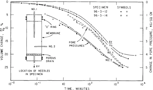
FIG. 6-Theoretical Pore Pressure Profiles Calculated From the Stress Profiles Given in Fig. 4. -0.2 0 0.2 0.4 0.6 0.8 1.0 1.2 1.4
Stress in Cylinder 0 Applhed Stress Q
a Cylinder of Elastic Material Axially Loaded Between Rough
1
I
UL =
Q
however, these stresses are considerablyu2 = u3 = 0 higher than the applied stresses.
Changes in pore water pressure in a At the restrained ends of the cylinder, body of saturated soil subjected t o shear-
/
ing stresses can be described by the ecluation
where il is a pore pressure coetlicient for the soil.
In a triaxial specinlen subjected to an applied stress change, Q, Aal
,
Au?,
and Aua will vary down the height of the specimen. One has only to study the results of any ~undrained triaxial com-A values. Sonle profiles calculated in this way are shown in Fig. 6.
The measured pore pressure parameter Azq'Q has been written as
A , the true pore pressure parameter for the soil a t any stress ratio
has been assunled to vary d o ~ v u the
Deviation F r o m C e n t r a l Pore P r e s s u r e ! I ! b , p e r cent
" 0
:I. Loading, :~xial strain 5 per cent.
I3. Loading, axial strain 14 1,er cent.
C. Unloading, axial strain 18.4 ller cent. D. Iteloi~dirlg, axial stn~in 17.S per cent. E. Itelonding, axial strain lS.G per cent.
The degree of equu1iz:ltion of pore yressure nt 14 per cent asin1 strain mas 40 per cent.
FIG. 7-Esperimental Pore Pressure Profiles Measured During Undrained Loading ol a Specimen of Saturated Clay.
pression test,' (such as shown in Fig. 9), to realize that the parameter A depends a great deal on the stress ratio
Hence A, too, will vary down the height of the triaxial specimen. If the stresses shown in Fig. 5 are assumed to apply, and if a stlitable variation of the parameter A is assumed, pore pressure profiles can be calculated for different
height of the specimen in accordance with the equations
The subscripts E and C refer respec- tively to the ends and inidheight of the specimen; H is half the specimen height; and z is measured from inidheight to- ward the ends of the specimen.
Three conclusions can be drawn froin Fig. 6:
1. Various coinbinations of true pore pressure values ./iE and ilc can lead to
profiles of pore pressure in which the inidheight value is either greater than, less than, or equal to the values a t the ends.6
2. T h e pore pressure parameter ineas- ured a t the ends of a triaxial specinlen does not correspond to the true pore pressure parameter A for the soil. The pore pressure parameter measured a t
various stages during the undrained loading and unloading of a saturated reinolded clay specimen. I t is apparent that inost of the types of profiles pre- dicted in Fig. 6 can in fact occur. Dur- ing loading the pore pressure a t mid- height was initially greater than that a t the base (Profile A ) . At a later stage the ~ r o f i l e was reversed (Profile Bl.
Unloading again caused a reversal of profile (Profile C). On reloading the profiles reverted to a type similar to Profile B.
Locating ubrlcated Latex DISC 8
Peg Pollshed Platen
0 2 4 6 8 10 1 2 14 16 18 2 0 a Axial Strain, p e r cent.
U 15
T h e degree of equalization of ]>ore pressure in 110th tests a t 10 per cent axial strain was 33 per cent.
k
-
Convent ional Plat ens
I
L u b r i c a t e d Platens
I I
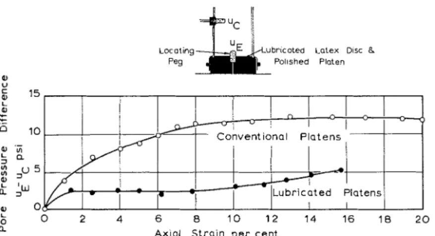
FIG. 8-A Comparison Between t h e Maximum Pore Pressure Diiference Measured in Triaxial Tests Using Conventional End Platens and Lubricated E n d Platens.
inidheight in a rapid test is much closer to the true value.
s
3. Although the pore pressures meas- ured in a very slow test will result in accurate ineasurement of shear strength
',
~ a r a m e t e r s in terms of effective stress, the corresponding values of the pore pressure parameter A may not be ac- curate.
Fig. 7 shows a series of experimental pore pressure profiles measured a t
G I t is not suggested that the values of AE , S c , and a used in Fig. 5 are all values likely t o occur in pnictice. T h e values used are possible but were selected mainly t o illustrate extrelne types of possible pore pressure profiles.
Special Measures to Elinzilsate the Effects of Etld Restraint:
I t appears that if end restraint due to friction could be eliminated from the triaxial test, the lot of the soil testing engineer would be much improved. Unfortunately, measures which reduce the effects of end restraint usually result in very difficult experimental techniques. Two techniques which have been used with varying success will now be de- scribed:
T h e Use of Lubricated E n d Platerls-
The triaxial specimen is loaded between platens having snlooth polished parallel
faces. Each end of the specimen bears used to measure pore pressures or to against a disk of thin rubber membrane permit drainage in a drained test. \vhich in turn is separated froin the Fig. 8 shows the results of pore pres- platen by a layer of silicone grease.' sure measurements on two specimens of The specimen is located by a peg in the a coillpacted clay loaded a t identical
0 2 4 6 8 1 0 12
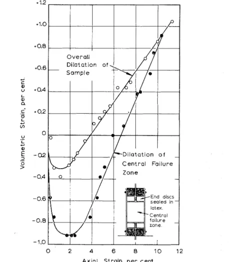
A x i a l Strain, p e r cent.
Volumetric strains occurred in .the central failure zone in a special test in which the central zone was isolated from the remainder of the specimen.
FIG. 9-A Comparison of Over-1\11 Volumetric Strains in a Conventional Drained Triasial Test. center of each platen. If these pegs are rates between lubricated and conven- made of porous material, they can be tional rough platens. Until an axial strain of 10 per cent was reached, the :The coefficient of friction between latex and lubricated platens caused a large reduc- polished brass lubricated with silicone grease is tion in the pore pressure 0.018. Between latex and lubricated polished
appeared to increase. Tests on remolded soils have not been as successful as tests on coillpacted soils, although a signifi- cant reduction in pore pressure difference has been achieved. Reductions in maxi- mum pore pressure difference brought about in this way allow the use of re- duced testing tiines for undrained tests. Testing times for drained tests would not be affected.
I s o l a t i o ~ ~ of the Celztral F a i l ~ t r s Zolze-
Reference to Fig. 5 shows that if the central two thirds of a triaxial specinlen could be isolated froin the end sections, and if illeasurements could be made only on this central portion, far inore uniform stress conditions would apply. Isolation of the failure zone can ge ichieved bv sealing the end one-sixth portions of a specinlen in self-vulcanizing latex and then enclosing the central two thirds together with the sealed end portions in a membrane in the usual way. I n un- drained tests pore pressures can be measured a t a probe a t inidheight or a t the base through a hole drilled in one of the end disks and then filled with a fine saturated sand. Drainage can take place through holes in the end disks or via filter paper strips passing between the outer nlenlbrane and the sealed end disks. Fig. 9 compares measurements of over-all voluilletric strain in a conven- tional drained test with voluilletric strains taking place in the central two thirds of a specimen with sealed disks a t its ends. The soil was a heavily over- consolidated saturated clay. The rate of dilatation of the central portion was almost twice that of the speciinen as a whole. This is of importance when ap- plying a dilatation correction to failure stresses in drained tests.s Although the central failure zone of the specimen tested in the conventional way was dilating, the end zones must have been conlpressing
"A
. W. Bishop, Correspondence, Giolech- q~iqile, Vol. 11, 1950, pp. 113-116.
or a t least were dilating a t a very much slower rate. These observations are siinilar to those made by Shockley and A h l v i n v n large-scale triaxial tests on dry sand.
1. The shape of the pore pressure profile set up in a rapid triasial test depends on the pore pressure parameter
.it for the soil and its variation with prin-
cipal stress ratio. True values of param- eter il cannot be obtained fro111 base measurenlents in a conventional triaxial test.
2. Eliinination of the eflects of end restraint allows shorter testing tinles to be used in undrained triaxial tests and should give truer measurements of the pore pressure parameter il.
3. The rate of dilatation illeasured in a conventional drained triaxial test may be considerably less than the rate of dilatation of the failure zone.
R. E . O ~ s o ~ ~ O - - T h i s discussion is divided into two parts covering pore water pressure measurements with nee- dles and membrane leakage.
Pore Tlrater Pressure ~Measz~re~ner~ts with ~l~eedles:
The author used needles successfully in the illeasurenlent of pore water pres- sures in specimens of sensitive Leda clay. I t appears that the high permeability and sensitive brittle structure of such clays make them ideally suited for such measurements. Needles would appear to be ideal for use with in~pervious clays too, b u t the following difficulties are encountered :
1. The insertion of the probe and the V. G. Shockley a n d R.. G. Ahlvin, "Xon- Uniform Co~lditioils in Triasial Test Specimens,"
P ~ o c e c d i n g s , Am. Soc. Civil Engrs., R.esearch
Conference on Shear Strength of Cohesive Soils, 1960.
lo Associate professor of civil engineering, D e p t . of Civil Engineering. University of I l - linois, Urbana, Ill.
rigidity of the probe during the shearing stage lnay disturb the specinlens and alter the pore water pressures. The problenl appears to be particularly severe when tests are perforined on highly sensitive but not brittle clays, because these clays have a very small resistance to disturbance.
2. If the speciinen fails a t strains above a few per cent, it appears that relative displacements between the tip of the needle and the soil iuay induce 5ignificant changes in the ineasured pore ir ater pressure.
3. T h e sinall contact area betm eel1 the needle and the soil inay pose serious ; roblems if the ambient temperature changes. If the teinperature increases, [he fluid in the measuring systein ex- pands. Since espansion is inhibited a t the nleasuring end of the pore Fressure line by the null indicator, the water inust flow into the specimen. For rela- tively iinpervious clays, the resistance of the clay to the flow causes increased apparent pore water pressures. T h e resulting error is a function of the rate of change of temperature and of the contact area between the sensing element and the soil. As an exaiuple of this problem, a sl~ecimen of dispersed sodiuin illite was consolidated to 80 psi, and the cell pressure and pore vvater rressure were siinultaneously increased by 40 psi and held constant for three days. Then the back-pressure valve was turned off and nleasureinents of pore water pressure and ambient temperature were obtained for ten days (Fig. 10). These pore vvater pressures were measured through a 1.5- in.-diameter porous stone. T h e use of a pore pressure needle would have resulted in inuch greater changes in apparent pore water pressure because of the smaller contact area between the probe and the specimen.
Mernbrmtze Leakage:
T h e author attempted to measure
leakage of cell fluid through thin rubber men~branes and concluded that mem- brane leakage was not a serious problem for short-term triaxial tests. H e noted that doubling the membrane had no apparent effect on the rate of leakage
T h e writer has obtained measure- inents of leakage through 0.002-in.-thick coinnlercial nleinbranes by using a 1.5- in.-diameter by 3.00-in.-high Norton P2120 porous stone in place of the soil s ~ e c i i n e n in a triaxial device and meas- uring the apparent volunle changes under constant cell pressure. T h e nlembranes were bound to the base pedestal using rubber bands and to the top cap using two rubber O-rings. Measurements were taken for periods up to six nlonths to ensure representative leakage rates. T h e following are typical observations: 1. Using a single inenlbrane with dis- tilled water on both sides and with the same amount of dissolved gas in the water on both sides, the leakage rate varied from 0.002 ml/day a t a cell pressure of 10 psi to 0.008 inl/day a t
75 psi.
2. With distilled water in the cell,
1-X CaCl? in the stone, and a cell pres- sure of 20 psi, the leakage rate was 0.090 nll/day for a single inembrane and 0.026 nll/day for two membranes sepa- rated by a thin layer of silicone high- vacuuin grease.
3. Using a single membrane and 1-ilr NaCl in the stone, the leakage rate varied from 0.032 ml/day a t a cell pressure of
5
psi to 0.050 ml/day a t 80 psi.
4. For comparison, direct nitrogen leakage through two inembranes a t a
cell pressure of 100 psi was 720 ml/day with no grease and 500 inl/day with the nlenlbranes separated by a thin layer of silicone high-vacuum grease. For nitro- gen in solution in water, the leakage rate was of the order of 50 ml/day.
I t appears that inenlbrane leakage can be reduced to about 0.002 ml/day if two meinbranes separated b y silicone
high-vacuum grease are used, provided that the concentration of dissolved gas and dissolved salt is the same in the cell fluid as in the pore fluid of the specimen and provided that cell pressures less than 120 psi are used. If lower leakage rates are desired, it appears that inercury should be used as the cell fluid. These conclusio~s are in substantial agreement with those expressed by the author.
WERNER E. SCEIA~ID"-T~~ careful experiments and research on the pore pressure variation within triaxial speci- inens by Crawford are rather interesting. His paper, as well as the one by G. E.
Blight, appears to be one of the inore significant clevelopnlents of this sym- ~ o s i u i n for the proper assessment of the shearing strength of clay soils.
Fronl 1957 to 1959 we measured pore pressures in a series of triaxial cell iests at various locations inside a test speci- men. The measurenlents were carried out by using con~n~ercially available pneu- matic relays that were inodified for pore pressure measurement. They established automatically a no-flow counter pressure equilibrium and indicated the pressure required to prevent flow on an ordinary bourdon gage. Since these relays were small and cheap, a number of them could be used siniultaneously. Thus a set of twelve such relays were arranged to measure pore pressures a t three different radial distances and a t four different heights of a triaxial test specimen 8 in. in diameter and 20 in. high. T h e results obtained" were rather interesting:
1. The pore pressures measured varied from point to point in a siinilar inanner as reported by Crawford and Blight.
2. Pore pressures varied not only from
point to point but also with time and with the time rate of loading.
3. Pore pressures were also a function of the strain.
4. The pore pressures were always measurecl with a certain time lag ob- servable by the fact, for example, that a n instantaneous increase i11 the cell pressure Q u a recluired a certain time before the pore pressure apparatus in- dicated a corresponding increase in Azl. This time lag was only partially a func- tion of the over-all coinpliance of the measuring system.
As a consecluence of all this we con- sidered i t quite tenuous to assume, as is usually clone, that the value of the pore pressure Z L , wherever, whenever, and by
whatever means observed (usually at the porous stone end of a specimen) is- eo ipso-the correct value for the proper detern~ination of the shear strength parameters of a clay soil.
The probleins and questions raised b y our observations were so serious that, in our opinion, they drew the reliability of the pore pressure approach into serious doubt. I t would have been easier perhaps to suppress our lnisgivings and calm our conscience by assigning all the inexpli- cable variations and discrepancies to the variation of Skempton's pore pressure coefficient A . Skempton in 1954lWerived a relationship between the pore pressure change Azl and the accompanying changes in total stress as:
According to Skempton B = 1.0 for saturated soils. If this formula was valid in our case the coefficient /I would have had to vary from point to point within the test specimen and also from instant 11 Associate l~rofessor of clvil engineering, to instant during the test, because with School of Engineering and Apl~lied Science,
Princeton Universitv. I'rinceton. N. 3. A u ~ = 0 for a saturated clay, Eq (1)
12 W. E. ~ c l u n i d , Y. I<latisl,er, ant1 C ~ I . F. reduces to AZL = L I A u ~ or A = A ~ L / A u ,
.
IIrhitmore, "Rheologicnl Sbenr nnd C:onsollda- ---
tion Behavior of C1:~y So~ls," Prooress R e p o ~ t to l3 A. W. S l i e l u ~ t o l ~ , "The Pore Pressure Co-
tlce Ofice of iVaual Research, Princeton, Decem- efficients A and B," Geotechniqz~e, Vol. IV, No.
Thus the pore pressure coefficient 11 is nothing but the pore pressure measured as a fraction of the applied stress A r 1 , and since All usually varies not only with stress but also with strain and time and, as we have observed, also with the loca- tion in the test specimen, it really can- not be considered more than a conveilient function that may vary arbitrarily in such a fashion as to match the esperi- nlentally observed pore pressures ZL with the applied stress. A function that varies in such a fashion is deceptive because it permits to establish a n apparent relation between any two arbitrary variables- however related or unrelated these may be. More than anything else, therefore, this pore pressure coefficient to us ap- peared as one of those "fudge factors" that are always necessary to reconcile inadequate theories with experimental data.
Several attempts to get around our dilemma, such as averaging in various con~binations, were unsatisfactory, and we fillally decided to investigate whether there were alternate methods of assess- ing shear strength-if possible without having to measure pore pressures. We soon found that the requirement of knowing the pore pressure resulted from uncritically accepting the i\iIohr-Coulomb failure hypothesis for clays, and that this was not a t all the one and only possible hypothesis available. Among several others there were a t least two, namely the Tresca and the von Mises hypotheses, that were promising. I n the course of our investigations we became inore and inore convinced that the undue emphasis on pore pressure measurements was not a t all advancing shear strength research but actually was stultifying it.
T o avoid any misunderstanding, we find it necessary to clarify one point: We do not claim that pore pressures do not exist (as we are sometimes accused), nor do we clainl that they are worthless
under any and all circumstances. Field values of pore pressures nlay be invalu- able for assessing the degree of consolida- tion of a clay layer and from that esti- mating the resulting shear strength.
What we do clainl is that the efforts necessary to assess the shear strength of clay soils on the basis of the effective stress principle with pore pressure meas- urements in the laboratory are not com- nlensurate with the accuracy, the re- liability, and the usefulness that results, considering all the assunlptions and un- certainties that are inherent to this method. These conclusions were reached as a consequence of the relatively great variability of the pore pressures that were observed within a test specimen throughout the loading process. I t is therefore a great satisfaction that other researchers like Crawford and Blight report similar experiences in pore pres- sure measurements as we have observed. Perhaps our arguments will now find a more open-minded audience.
I n our search for a fresh approach to the shear strength problem we found that soil engineers had inherited inany habits of thought and action or had accepted thein without critical analysis. I t is refreshing to observe how inore and more people now are suggesting to rethink the problem from the very beginning.
We are gratified to see A'Iessrs. Roscoe, Schofield, and Thurairajah state, as we have done earlier,12 that the extended von IiIises or Tresca failure criteria are nlore relevant than Mohr-Coulomb. We only wish to add here that they are also less c~unbersome in their application to practical design problems.
Mr. Crawford states that pore pressure measurements taken a t various points within a soil specimen are confusing. We agree. With that much evidence to the contrary it is difficult, however, to accept his hypothesis that it seems reasonable
to assuine that the pore pressures on the failure plane and those a t the base plate are almost equal. This appears to be a typical argument to brush the incon- sistencies under the rug: Why get con- fused? Let us nleasure pore pressure a t the base and assunle that all is well. h'obody can get confused that way.
Unfortunately, in the research field of shear strength of clay soils we find a seeillingly unalterable, generally accepted dognla about the validity of the Mohr- Coulomb hypothesis. Actually this hy- pothesis, as it is applied, is a strangely construed mixture of experimental ob- , servations, assumptions, and speculation. We believe one of the most urgent re- cluirements to clear up the probleill would be to separate fact from fiction.
A detailed discussion of a illore prom- ising shear strength theory would be beyond the scope of this d i s ~ u s s i o n . ~ ~ J ~ We may, however, just sununarize some points that are essential:
1. Clays in general are visco-elastic- plastic materials and their load-deforma- tion behavior is time-dependent. The theory that satisfactorily perinits to describe this behavior, therefore, must be a rheological one.
2. Mie nlust recognize that the shear strength of a clay soil is also a rheological cluantity, that is, that it is not a unique value but it runs through a spectrum of values depending on the rate of loading.
3. The von Mises or Tresca failure conditions are independent of any nor- mal stress and therefore do not require any pore pressure measurement, nor do they require the artificial separation of shear strength into a cohesion and a friction component. These conlponents in any event always have to be reconl- 1" W. E . Schmid, "New Colicel~ts of Slienring Strength for Clay Soils," I'art 1 , Sols-Soils,
Vol. 1 , 1 , Paris, 1962, 1313. 31-42.
'"V. E . Schniicl, "New Concepts of Shearing Strength for Clay Soils," P:lrt 11, Sols-Soils,
Vol. 1 , 2, Paris, 1962, pp. 19-26.
bined in the solution of practical prob- l ems.
4. We ~ l l ~ i s t recognize the fact that, when a given soil changes fro111 one effective stress to another effective stress, it really changes into a different en- gineering material.
5. The shear strength can be expressed in analogy to the old Mohr-Coulomb hypothesis by using the concept of the intrinsic stress such that s =
pi
tan4* = ( ( ~ i
+
(T - ZL) tan 4* wherepi
isthe intrinsic stress and exists between the soil grains in the absence of any pore pressure or exterior stress.lG
Finally we wish to commend the care- ful experimental work by Mr. Crawford. Only those who have ever measured pore pressures in the laboratory can appreciate the diligence required to produce results as Mr. Crawford has done.
CARL 13. CRAWFORD (az~fhor's clo- sure)- Until recently some of the unusual features of triaxial test results were assumed to be caused by meinbrane leakage. Professor Olson's estensive test results are therefore a welconle cor- roboration of the writer's observation that leakage through the rubber mein- brane is not a serious problenl for ordinary tests. Leakage due to inlproper seals can, of course, be very serious.
Professor Olson's study of gas diffu- sion is also of special interest. Gas diffusion can be just as serious through plastic hose as through the membrane, and it should not be used in the pore pressure system without checking this property. A siinple test of plastic hose is to fill a short length with de-aired water, seal both ends, and observe it for a few days. Usually air voids will begin to appear within a few hours.
l G W. E. Schlnid arid S. Kitngo, "Slieur Strength of Clays and Safety Factors as n Func- tion of Time," Proceedings, Sisth Inter~lational Conference ISSLIFE.
Now that pore pressure variation within triaxial specilllens is a well established phenomei~on, it is probable that much research will be devoted to it, and the problems with the use of probes, as cited by Professor Olson, will require continuing attention. T h e problem of inserting a needle into the undisturbed sensitive Leda clay is probably not nearly so serious as it is in inost re- inolded soils, because the tiny hole re- quired is made very easily with a drill (slightly sinaller than the needle), and this appears to have little effect on the relatively strong undisturbed specimen. T h e limited nuinber of tests with needles showed no tendency to lower strengths. T h e second and third probleins noted are difficult to assess and will require further study. I n the tests described in the paper the cell pressure and the pore pressure systeins were increased simul- taneously and after standing a t equilib- rium for a short time the drainage mas opened, giving results such as those shown in Fig. 3. Attempts to follow the pore pressure change resulting from increments of ambient pressure mere generally unsatisfactory due to plugging
of the needle. This suggests an outward f l o ~ ~ which could not be overcome. T h e method can only be evaluated, therefore, by judging the perforn~ailce during consolidation and shear. Obviously inl- provements in the technique are re- quired, but the measurements made a t present do not appear to be unreasona- ble.
Teinperature influences on ineasured pore water pressure nlust be of considera- ble iinportance as indicated by Professor Olson and other contributors to the conference. This is another factor in testing that must have more attention in the future, especially for long-term tests during which substantial temperature changes occur.
Professor Olson recognizes the need
for internal pore pressure ineasureinents in order to reduce testing times. T h e writer has tried to indicate in discussion of Dr. Blight's paper17 that the pore pressure variations in a sensitive clay are due largely to time-dependent struc- tural collapse, and if the test is to represent undrained shear, it may be iinpossible t o achieve pore pressure equalization with the base plate a t prac- tical rates of shear. Nevertheless the base nleasureinents cluoted in the paper are considered to be satisfactory because the shear plane is so near to the base.
Dr. Blight has produced valuable in- formation regarding the pore pressure and dilatancy variation within triaxial specinlens and has de~nonstrated the influence of end restraint on pore pres- sures. His Fig. 5, however, appears to be an oversiinplification, since the average stress, 0 1 , over the diameter a t the base of a cylinder inust equal the applied stress, Q. T h e vertical stress a t the edge of the base inay be greater than the applied stress.
Soine confusion may result froin Dr. Blight's reference to the variation in parameter A a t various levels in the specimen. Paraineter A is a reflection of the dilatancy characteristics of the soil and should be the saine a t equal levels of stress and strain for a uniforin soil. T h a t it varies is due to the inequalities of stress and strain a t any particular time during the test, and it is suggested that i t is inore correct to einphasize this fact.
Professor Schnlid doubts that it is reasonable to assume that pore pres- sures on the failure plane are allnost eclual to those measured a t the base plate. This was deliberately stated with caution in the conclusions because of the inany uncertain influences, even though Fig. 3 shows it to be true for typical tests. T h e purpose of the study was to
evaluate this very cluestion, and the results may be interpreted in a variety 3 f ways depending on the reader's point of view.
Professor Sch~nicl finds most of the co111111011 shear strength concepts ap- plied to soils to be unacceptable. T h e writer's only response to this is t h a t the alternatives are, a t the moment, less acceptable. T h e problenls of stress, strain, and pore pressure variatioils do not disappear with the rejection of i\/lohr-Coulomb or by abandoning the
triaaial shear device, although both of these possibilities merit study. I t is probably true that most research ~vorkers relied too heavily on base nleasurenlents of pore pressure during the time of the London Conference in 1957, when the effective stress concepts mere first cle- veloping on a practical basis. But this situation mas corrected quickly, arld by 1960 inany references could be found to the possible errors in accepting base measurements, and this is now a subject of intensive study.