Publisher’s version / Version de l'éditeur:
Vous avez des questions? Nous pouvons vous aider. Pour communiquer directement avec un auteur, consultez la première page de la revue dans laquelle son article a été publié afin de trouver ses coordonnées. Si vous n’arrivez pas à les repérer, communiquez avec nous à [email protected].
Questions? Contact the NRC Publications Archive team at
[email protected]. If you wish to email the authors directly, please see the first page of the publication for their contact information.
https://publications-cnrc.canada.ca/fra/droits
L’accès à ce site Web et l’utilisation de son contenu sont assujettis aux conditions présentées dans le site LISEZ CES CONDITIONS ATTENTIVEMENT AVANT D’UTILISER CE SITE WEB.
Internal Report (National Research Council of Canada. Division of Building
Research), 1983-10
READ THESE TERMS AND CONDITIONS CAREFULLY BEFORE USING THIS WEBSITE.
https://nrc-publications.canada.ca/eng/copyright
NRC Publications Archive Record / Notice des Archives des publications du CNRC :
https://nrc-publications.canada.ca/eng/view/object/?id=928891ba-4f4b-4467-88d6-465ec7098618 https://publications-cnrc.canada.ca/fra/voir/objet/?id=928891ba-4f4b-4467-88d6-465ec7098618
NRC Publications Archive
Archives des publications du CNRC
For the publisher’s version, please access the DOI link below./ Pour consulter la version de l’éditeur, utilisez le lien DOI ci-dessous.
https://doi.org/10.4224/40001323
Access and use of this website and the material on it are subject to the Terms and Conditions set forth at
Fire tests on reinforced concrete columns: specimen no. 4
FIRE TESTS ON REINFORCED CONCRETE COLUMNS, SPECIMEN NO.
4
by
T.T.
Lie and T.D. Lin
National Research Conseil national T:
:
27
)
#
Council Canada de recherches CanadaDBR
Internal Report 481 Private copy for:NATIONAL RESEARCH COUNCIL OF CANADA DIVISION OF BUILDING RESEARCH
OBR INTERNAL REPORT NO. 481
FIRE TESTS ON REINFORCED CONCRETE COLUMNS, SPECIMEN NO. 4 by T.T. Lie and T.D. Lin
Checked by: T. 2 . Harmathy Approved by: L . W . Gold Date: October 1983
Prepared for: Records Purposes
ABSTRACT
Results of a fire test on a reinforced concrete column are given. The test is one of a series of twelve tests carried out in the first phase of a joint study on the fire performance of concrete columns by the National Research Council of Canada and the Portland Cement Association. The column was made with siliceous aggregate; section size was 305 x 305 mm (12 x 12 in.). The purpose of the test was to study the influence of load on the fire resistance of the column.
FIRE TESTS ON REINFORCED CONCRETE COLUMNS SPECIMEN NO. 4
T.T. Lie and T.D. Lin
Tests were carried out on a series of reinforced concrete columns as part of a study to develop methods for determining the fire
resistance of such columns. The study was a cooperative effort between the National Research Council of Canada and the Portland Cement
Association. In the first phase of the study, 12 columns were tested. The columns were designed and manufactured by PCA in Skokie, Illinois, and tested in the NRCC laboratories in Ottawa. The specimens, method of testing and test results are described in successive reports.
This report deals with specimen No. 4, which was tested to investigate the influence of load on the fire resistance of the column.
TEST SPECIMEN
The specimen consisted of a square tied reinforced concrete column. Details on the specimen and its fabrication are given below.
Section size: 305 x 305 mm (12 x 12 in.) Height: 3810 mm (12 ft 6 in.)
Materials
Cement: Type I, a general purpose cement for the construction of reinforced concrete structures.
Aggregate: Siliceous sand and gravel from Eau Claire, Wisconsin. The maxiwm size of the aggregate was 19 mm (314 in.). The gradation
curve is shown in Fig. 1. Petrographic information on the aggregate, obtained according to ASTM ~295-79l, is given in Table
1.
The physical properties of the aggregate are given in Table 2 .Steel Reinforcement: Deformed 25M (No. 8) longitudinal
reinforcing bars and 10 M (No. 3) ties, meeting the requirements of ASTM Designation ~615-602. The yield strength of the 25M bars was 443.7 MPa (64.3 ksi) and that of the 10M bars, 426.5 MF'a (61.8 ksi).
Concrete Mix: The concrete mix was designed to produce a 34.5 MPa (5000 psi) strength non-airentrained concrete.
A
watercement ratio of 0.6 was used. The slump was 84 mm (3.29 in.). Batch quantities are given in Table 3 and measured properties of the concrete in Table 4.F a b r i c a t i o n Casting
The column was c a s t i n a s p e c i a l l y designed form. A t t h e s t a r t of t h e c a s t i n g t h e f r o n t s i d e of t h e form was l e f t open f o r d e p o s i t i n g f r e s h concrete. The c o n c r e t e was mixed i n a 0.17 m 3 (6 f t 3 ) t i l t i n g drum mixer. Shovels and scoops were used t o d e p o s i t c o n c r e t e i n t h e form. A small i n t e r n a l v i b r a t o r was a p p l i e d t o c o n s o l i d a t e t h e concrete.
As
c a s t i n g progressed upwards, t h e window p i e c e s were s u c c e s s i v e l y closed and t i g h t l y bolted t o t h e form t o avoid p o s s i b l e moisture l e a k s . L i f t i n g hooks were embedded on o p p o s i t e s i d e s of t h e t e s t specimen a t 800 mm (2 f t7i
in.) from t h e t o p of t h e column. Ac y l i n d r i c a l humidity w e l l 3 w i t h a diameter of 4 mm (5132 i n . ) was positioned a t mid-height of t h e column f o r measuring t h e r e l a t i v e humidity a t mid-depth.
Reinforcing cage
The r e i n f o r c i n g cage was assembled by welding each end of f o u r l o n g i t u d i n a l main r e i n f o r c i n g b a r s t o a s t e e l end p l a t e . The b a r s were cut t o 3800 imn (12 f t 51 in.) and machined a t both ends, f o r a l e n g t h of 19 mm (314 in.) t o a diameter of 19 mm (314 i n . ) . Fig. 2 shows d e t a i l s of t h e f i n i s h e d bars. The dimensions of t h e end p l a t e s were 533 x 533 x 25 mm (21 x 21 x 1 in.). I n each c o r n e r of t h e p l a t e ,
20.6 mm (13116 i n . ) h o l e s were d r i l l e d t o accommodate t h e l o n g i t u d i n a l bars. The c e n t e r s of t h e h o l e s were spaced 92.1 mm (3 518 in.) from the c e n t e r l i n e s of t h e p l a t e s . I n t h i s way a column was obtained w i t h a s e c t i o n of 305 x 305 mm (12 x 12 in.) and a cover of 47.6 mm
( 1 718 i n . ) t o t h e main r e i n f o r c i n g b a r s and 38.1 mm ( 1 112 i n . ) t o t h e s t i r r u p s . The main b a r s and s t i r r u p s were t i e d t o g e t h e r t o complete the s t e e l cage which, i n c l u d i n g t h e s t e e l p l a t e s , was 3810 mm
(12 f t 6 i n . ) long. Welding
The p r o v i s i o n s of AWS Designation ~ 1 2 . 1 - 7 5 4 were followed f o r welding p l a t e s and bars. These members were preheated w i t h a propane t o r c h t o 288°C (550°F), t o prevent b r i t t l e f a i l u r e during welding. The s i d e f i l l e t weld was done around b a r s on t h e i n n e r f a c e of t h e bottom p l a t e . McKay E10018-D2 and DYTRON-579 welding rods were used. Both types of welding rods have t e n s i l e s t r e n g t h of 834.9 MPa (121 000 p s i ) . Mild-steel welding rods were used t o f i l l up the 6 mm (114 in.) deep h o l e s on t h e o u t e r f a c e s of t h e p l a t e . The rough s u r f a c e s of t h e welded j o i n t s on t h e o u t e r f a c e of t h e p l a t e were ground t o a smooth
f i n i s h . The welding of t h e t o p s t e e l p l a t e was done a f t e r t h e c a s t i n g of t h e columns. Before p o s i t i o n i n g t h e t o p p l a t e , a 6 mm (114 i n . ) l a y e r of mortar was s p r e a d o v e r t h e t o p of t h e column t o e n s u r e good contact between s t e e l p l a t e and concrete. The mortar was made of one p a r t cement and t h r e e p a r t s s i l i c e o u s sand. Using t h e same procedure a s f o r t h e bottom p l a t e , t h e t o p p l a t e was welded on t h e o u t e r s i d e t o t h e b a r s and smoothed.
Curing,
The concrete was cured under damp b u r l a p f o r 7 days a t 21 t o 24°C (70 t o 75'F). The form was t h e n s t r i p p e d , and t h e column conditioned
i n an atmosphere c o n t r o l l e d a t 21 t o 24'12 (70 t o 75'F) and 30 t o 40% r e l a t i v e humidity. The column was removed from t h e k i l n p e r i o d i c a l l y t o cool a t 23'C (73'F) so t h a t t h e r e l a t i v e humidity could be measured. Moisture c o n t e n t i n t h e column during t h e d r y i n g period i s given
below.
Days a f t e r R e l a t i v e humidity c a s t i n g c e n t e r of column ( % )
8 3 9 5
287 8 7
A t 287 days a f t e r c a s t i n g , t h e contemplated moisture c o n d i t i o n was reached, and t h e column was wrapped i n p l a s t i c t o prevent change i n moisture content.
Butt-welded chromel-alumel thermocouples with a t h i c k n e s s of 0.912 mm (0.0359 i n . ) were used t o make thermocouple frames f o r
measuring c o n c r e t e temperatures a t d i f f e r e n t l o c a t i o n s i n v a r i o u s c r o s s s e c t i o n s of t h e columns. Each frame c o n s i s t e d of a number of thermc- couples t i e d t o s t e e l rods t h a t were f i r m l y secured t o t h e main
r e i n f o r c i n g bars. Temperatures were measured a t t h r e e l e v e l s : a t one- q u a r t e r h e i g h t , a t mid-height and a t three-quarters h e i g h t of t h e column. A t mid-height t h e temperatures were measured along t h e whole l e n g t h of a c e n t e r l i n e and a diagonal of t h e s e c t i o n ; a t t h e o t h e r two l e v e l s t h e temperatures were measured only along h a l f of t h e c e n t e r l i n e and h a l f of t h e diagonal of t h e s e c t i o n . The l o c a t i o n of t h e
thermocouples i n t h e c o n c r e t e and t h e i r numbering a r e shown i n Figs. 3
and 4.
I n a d d i t i o n , a number of thermocouples were mounted on t h e
r e i n f o r c i n g s t e e l b a r s and t i e s . The l o c a t i o n s of t h e thermocouples on the s t e e l a r e shown i n Fig. 5 and i n more d e t a i l i n Fig. 6.
A l l thermocouples were i n s t a l l e d i n such a way t h a t t h e w i r e
followed a n isotherm over a d i s t a n c e of a t l e a s t 12.7 m a (112 i n . ) from t h e junction.
T e s t Apparatus
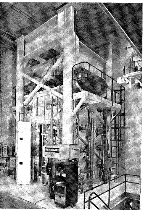
The t e s t was c a r r i e d out by exposing t h e column t o h e a t i n a f u r n a c e s p e c i a l l y b u i l t f o r t h e t e s t i n g of loaded columns and w a l l s . The t e s t furnace was designed s o t h a t i t could produce t h e c o n d i t i o n s
t o which a member might be exposed during a f i r e , such a s f i r e temperatures, s t r u c t u r a l l o a d s , and heat t r a n s f e r . It c o n s i s t s of a s t e e l framework supported by f o u r s t e e l columns w i t h t h e f u r n a c e
chamber i n s i d e t h e framework (Fig. 7 ) . The c h a r a c t e r i s t i c s and
i n s t r u m e n t a t i o n of t h e f u r n a c e a r e d e s c r i b e d i n d e t a i l i n r e f e r e n c e 5. Only a b r i e f d e s c r i p t i o n of t h e furnace and t h e main components w i l l be given here.
Loading Device
Three h y d r a u l i c j a c k s produce f o r c e s along t h e t h r e e p r i n c i p a l axes. The jack a c t i n g a l o n g t h e a x i s of t h e t e s t column i s l o c a t e d a t t h e bottom of t h e furnace chamber. The p l a t e on t o p of t h i s jack can be used a s a p l a t f o r m t o which t h e column can be a t t a c h e d .
Furnace Chamber
The furnace chamber has a f l o o r 2642 mm (8 f t 8 i n . ) on each s i d e and i s 3048 mm (10 f t ) high. It i s made of i n s u l a t i n g m a t e r i a l s t h a t w i l l produce a high h e a t t r a n s f e r t o t h e specimen. There a r e 32
propane g a s burners i n t h e f u r n a c e chamber, arranged i n e i g h t columns, containing f o u r burners each. The t o t a l c a p a c i t y of t h e burners
i s
4700 kW (16 m i l l i o n Btufh). Each burner can be a d j u s t e d i n d i v i d u a l l y , allowing a high temperature uniformity i n t h e furnace chamber. The p r e s s u r e i n t h e f u r n a c e chamber i s a l s o a d j u s t a b l e . It was s e t somewhat lower than atmospheric pressure.
Instrumentation
The furnace temperatures were measured w i t h t h e a i d of e i g h t chromel-alumel thermocouples. The j u n c t i o n of each thermocouple was l o c a t e d a t a d i s t a n c e of 305 mm ( 1 f t ) from t h e t e s t specimen a t v a r i o u s h e i g h t s . There were two thermocouples placed o p p o s i t e each o t h e r every 610 mm (2 f t ) along t h e h e i g h t of t h e f u r n a c e chamber. The l o c a t i o n of t h e i r j u n c t i o n s and t h e i r numbering a r e shown i n Fig. 8. Thermocouples No. 4 and 6 were l o c a t e d a t a h e i g h t of 610 mm (2 f t ) from t h e f l o o r , Nos. 2 and 8 a t 1220 mm (4 f t ) , Nos. 3 and 5 a t 1830 mm ( 6 i t ) and Nos. 1 and 7 a t 2440 rn (8 f t ) . The temperatures measured by t h e thermocouples a r e averaged a u t o m a t i c a l l y and t h e average temperature used a s t h e c r i t e r i o n f o r c o n t r o l l i n g t h e furnace temperature.
The l o a d s were c o n t r o l l e d and measured with t h e a i d of p r e s s u r e transducers. The accuracy of c o n t r o l l i n g and measuring l o a d s were approximately 5% a t lower load l e v e l s and b e t t e r a t h i g h e r loads.
The a x i a l s t r a i n of t h e t e s t specimen was determined by measuring t h e displacement of t h e jack t h a t s u p p o r t s t h e column. The
displacement was measured w i t h t h e a i d of t r a n s d u c e r s w i t h an accuracy of 0.002 mm.
Test Conditions and Procedure
The column was i n s t a l l e d i n t h e f u r n a c e by b o l t i n g i t s end p l a t e s t o a loading head a t t h e t o p and a h y d r a u l i c jack a t t h e bottom. Eight
19 mm (3/4 in.) b o l t s , spaced r e g u l a r l y around t h e column 63.5 mm (21 i n . ) from t h e s i d e s , were used a t each end. On t h e day of t h e
t e s t , t h e moisture c o n d i t i o n i n t h e c e n t e r of t h e column was measured with a Monfore gauge3. The r e l a t i v e humidity p r i o r t o t h e s t a r t of t h e t e s t was 63%. The ambient temperature a t t h e s t a r t of t h e t e s t was 21°C (70°F).
The column was c a s t J u l y 20, 1977 and t e s t e d March 19, 1980. It
was s u b j e c t e d t o a load of 711 IcN (160 k i p s ) a p p l i e d about one hour p r i o r t o t h e t e s t . The c y l i n d e r s t r e n g t h s of t h e c o n c r e t e on t h e t e s t d a t e , measured on t h r e e c y l i n d e r s , were r e s p e c t i v e l y 35.9 MPa
(5199 p s i ) , 34.5 MPa (4996 p s i ) and 35.8 MPa (5190 p s i ) .
During t h e t e s t t h e column was exposed t o h e a t i n g c o n t r o l l e d s o t h a t t h e average temperature i n t h e f u r n a c e followed a s c l o s e l y a s p o s s i b l e t h e A S T M - E ~ ~ ~ ~ o r U L C - S ~ O ~ ~ standard temperature-time curve. This curve can be approximately described by t h e following e q ~ a t i o n : ~
where T f = temperature i n O C , and T = t i m e i n h where T f = temperature i n O F , and T = time i n h
During t h e t e s t , t h e temperatures i n t h e f u r n a c e and i n t h e column were measured a t t h e v a r i o u s l o c a t i o n s d e s c r i b e d e a r l i e r . The a x i a l deformation of t h e column was a l s o measured. The column was considered t o have f a i l e d , and t h e t e s t was terminated, when t h e h y d r a u l i c j a c k , which has a maximum speed of 76 mmfmin (3 in./min), could no longer maintain t h e a p p l i e d load.
TEST RESULTS
Ilaaured Temperatures and D e f o r ~ t i o a
The temperatures of t h e s t e e l f o r v a r i o u s times a r e given i n Table 5. The temperatures measured i n t h e c o n c r e t e s e c t i o n s a r e given i n Tables 6A t o 6D.
The average furnace temperature i s given i n Table 7 and t h e measured a x i a l deformation of t h e column f o r v a r i o u s times during t h e t e s t ts given i n Table 8.
Observationr
The observations made during t h e test a f t e r v a r i o u s exposure times a r e given below.
45 min: A v e r t i c a l crack, 100 t o 125 mm (4 t o 5 i n . ) long. appeared on t h e e a s t f a c e of t h e column, about 450 mm (18 in.) from t h e bottom of t h e furnace.
60 min: Long h a i r l i n e v e r t i c a l c r a c k s t h a t followed t h e main
r e i n f o r c i n g s t e e l l o c a t e d i n t h e s o u t h e a s t c o r n e r were s e e n on both s o u t h and e a s t s u r f a c e s of t h e column. Fig. 9 shows the general l o c a t i o n of t h e s e cracks.
180 min: The c r a c k s on t h e e a s t f a c e were 300 mm ( 1 2 i n . ) long and 3 t o 6
mm
(118 t o 114 i n . ) wide.The column f a i l e d a t 3 h 40 min. It was caused by crushing of t h e c o n c r e t e and buckling of t h e main r e i n f o r c i n g bars.
Fig. 10 shows a schematic view of t h e column a t t h e end of t h e t e s t . Fig. 11 s h w s a p a r t of t h e column i n t h e f u r n a c e chamber a f t e r t h e t e s t . The c o n c r e t e has been removed t o show t h e r e i n f o r c i n g bars.
Using t h e method d e s c r i b e d i n r e f e r e n c e 9, t h e temperatures of t h e main r e i n f o r c i n g s t e e l , and t h e temperatures a t v a r i o u s depths i n t h e
concrete s e c t i o n s were c a l c u l a t e d . For t h e r e i n f o r c i n g s t e e l t h e temperature a t t h e c e n t e r was chosen a s r e p r e s e n t a t i v e of t h e average temperature of the s t e e l . Fig. 12 shows two average temperatures obtained from measurements on two r e i n f o r c i n g b a r s d u r i n g t h e t e s t . These measurements were made with thermocouples No. 3 and 9 l o c a t e d on
one b a r o p p o s i t e each o t h e r w i t h r e s p e c t t o t h e c e n t e r of t h e bar, and with thermocouples No. 4 and 10, l o c a t e d on another b a r , a l s o o p p o s i t e each o t h e r (Fig. 6). The temperatures measured on t h e s t e e l by t h e i n d i v i d u a l thermocouples a r e shown i n Fig. 13. The d i f f e r e n c e i n temperature between two o p p o s i t e p o i n t s of a bar i s r e l a t i v e l y small.
I n Fig. 14, t h e temperatures shown a r e measured along a c e n t e r l i n e i n t h e c o n c r e t e s e c t i o n a t mid-height a t v a r i o u s depths. The curves show a f a i r l y good agreement between measured and c a l c u l a t e d
temperatures.
Fig. 15 shows a comparison between t h e c a l c u l a t e d a x i a l
deformation and t h a t measured during exposure t o f i r e . The c a l c u l a t e d f a i l u r e time was 215 minutes, s l i g h t l y lower than t h e measured f a i l u r e time of 220 minutes.
1. Standard P r a c t i c e f o r Petrographic Examination of Aggregates f o r Concrete (1979). ASTM C295-79, American S o c i e t y f o r T e s t i n g and M a t e r i a l s , P h i l a d e l p h i a , PA.
' 2 . Standard S p e c i f i c a t i o n f o r Deformed and P l a i n B u l l e t - S t e e l Bars f o r Concrete Reinforcement (1980). ASTM A615-80, American S o c i e t y f o r Testing and M a t e r i a l s , P h i l a d e l p h i a , PA.
3. Monfore, G.E. (1962). A Small P r o b e q y p e Gauge f o r Measuring R e l a t i v e Humidity. J o u r n a l of t h e PCA Research and Development L a b o r a t o r i e s , Vol. 5, No. 2.
4. Reinforcing S t e e l Welding Code (1975). AWS-D12.1-75, American Welding S o c i e t y , Manlius. NY.
5. L i e , T.T. (1980). New F a c i l i t y t o Determine F i r e Resistance of Columns, Canadian J o u r n a l of C i v i l Engineering, Vol. 7 , No. 3.
6.
Standard Methods of F i r e T e s t s of Building Construction andM a t e r i a l s (1979). ANSI/ASTM E119-79, American S o c i e t y f o r T e s t i n g and M a t e r i a l s , P h i l a d e l p h i a , PA.
7. Standard Methods of F i r e Endurance T e s t s of Building C o n s t r u c t i o n and M a t e r i a l s (1980). ULC-S101-Ml980, Underwriters' L a b o r a t o r i e s of Canada, Scarborough, Ontario.
8. Lie, T.T. and Harmathy, T.Z. (1972). A Numerical Procedure t o C a l c u l a t e t h e Temperature of P r o t e c t e d S t e e l Columns Exposed t o F i r e . F i r e Study No. 28, D i v i s i o n of Building Research, National Research Council of Canada. Ottawa, Ontario, NRCC 12535.
9. Lie, T.T., Allen, D.E., Lin, T.D. and Abrams, M.S. F i r e R e s i s t a n c e of Reinforced Concrete Columns, D i v i s i o n of Building Research, National Research Council of Canada, Ottawa. To be published.
TABLE 1 PETROGRAPHY OF SAND AND GRAVEL USED AS AGGREGATE
Composition of S i e v e F r a c t i o n , P e r c e n t on S i e v e of S i z e I n d i c a t e d Percent
Component Passing
19 mm 12.5 mm 9.5 mm 6mm No. No. No. No. No. No. No. through
4 8 16 30 50 100 200 No. 200 G r a n i t e 37.9 32.9 25.5 31.3 27.0 27.6 12.3 7.4 1.9 4.4 0.6
-
Q u a r t z i t e 21.6 29.2 34.8 24.6 24.5 20.0 12.3 12.6 10.9 3.1 2.2--
Quartz 6.3 3.1 4.9 4.8 5.5 18.8 52.2 62.0 73.1 79.5 74.2 92.0 Sandstone-Quartz Congloraerate 1.9 0.8 3.1 5.1 5.5 8.3-
-
--
--
--
--
Rhyolite-Dacite 13.9 6.2 2.2 5.1 7.2 4.1 0.8 2.6 1.6 0.8 0.9--
F e l d s p a r-
-
-
-
-
-
1.3 5.0 6.6 5.0 10.8 4.0 D i o r i t e 1.9 1.4 3.1 1.8 1.2-
--
--
--
-
-
Graywacke b 1.3 9.5 5.8 5.4 4.3 6.5 2.3 1.5 0.3--
0.6--
Gneiss-Schist 2.5 5.1 10.5 9.3 7.5 4.1 6.4 1.8 0.9 1.1 0.6-
B a s a l t 1.9 4.5 4.0 3.9 6.9 3.2 2.6 2.4 0.7-
0.3--
Mist. Igneous Rocks and Opaque Minerals-
0.3 0.9 0.6 0.6 1.5 2.1 1.2 2.0 5.3 7.0 2.0P a r t i c l e Shape 19 t o 6 rms (%) No. 4 t o No. 16 ( % I No. 30 t o No. 200 (%) Subrounded t o rounded
Subrounded t o suhangular Angular
a " ~ r a n s t o n e . " made up of j a s p e r and hematite, i s i n c l u d e d i n t h e c h e r t c l a s s i f i c a t i o n . . .
' ~ n c l u d e s &tagraywake.
%he miscellaneous igneous r o c k s were s e v e r e l y a l t e r e d and p o s i t i v e i d e n t i f i c a t i o n was impossible. The opaque m i n e r a l s occurred i n t h e No. 50 and s m a l l e r s i e v e s i z e s and were l a r g e l y magnetite.
TABLE 2 PHYSICAL PROPERTIES OF AGGREGATE
Specific gravity of sand 2.63
Specific gravity of gravel 2.57
Moisture content of sand, % 4.0
Moisture content of gravel, %
1.0
Saturated surface dry unit weight
of gravel kg/m3 1678
Fineness modulus of fine aggregate 2.96
Fineness modulus of coarse aggregate 1.73
TABLE 3 BATCH QUANTITIES
Item Quantity (kg/m3) Cement 307.3 Coarse aggregate 1054.3 Sand 871.5 Water 153.7
TABLE 4 PROPERTIES OF CONCRETE
Property Quantity
-
Air content
Density
Compressive strength at
TABLE 5 MEASURED STEEL TEMPERATURES Temperature ( O C ) Measured a t Thermocouple No: Time b i n ) 1 2 3 4 5 6 7 8 9 10 *Measurement not r e l i a b l e
TABLE 6A CONCRETE TEMPERATURES MEASURED WITH THERMOCOUPLES I N FRAME A T e m p e r a t u r e ( OC) Measured a t Thermocouple No: Time (min) 1 1 12 1 3 14 15 16 17 1 8 19 20 21 22 23 24
n
71 21 21 21 21 21 21 21 2 1 21 21 2 1 21 2 1 5 107 71 46 32 24 24 21 21 2 1 27 4 1*
9 1 5 1 10 168 116 77 46 27 24 2 1 2 1 29 66 107 158 263 164 1 5 274 185 124 85 3 8 24 24 24 52 118 179 271 426 277 20 349 249 163 121 63 27 24 32 99 152 265 380 523 363 25 432 318 216 141 102 34 27 46 107 191 333 453 590 425 30 466 346 235 149 102 57 32 57 110 241 392 512 649 485 3 5 518 399 282 191 104 66 3 8 66 115 288 446 561 695 532 40 541 421 304 213 104 6 8 52 79 127 329 494 611 737 571 45 579 463 346 246 116 77 6 0 8 8 1 4 3 366 533 649 761 599 50 596 482 363 263 121 8 5 68 102 163 399 568 6 8 t 789 632 55 643 521 399 291 135 96 79 110 185 427 607 723 828 667 60 663 546 427 310 141 118 88 1 1 8 204 454 639 744 834 679 70 691 579 463 349 171 124 116 132 243 496 683 774 855 708 8 0 716 610 493 377 193 129 127 1 4 3 282 532 718 801 877 736 9 0 738 635 518 399 218 141 132 163 316 566 747 826 895 759 100 757 660 538 418 235 154 135 185 349 593 772 848 913 7 8 3 110 779 682 563 438 257 171 143 210 382 627 797 872 934 8 0 8 120 799 702 585 460 277 188 149 232 410 652 820 889 948 8 2 8 130 816 721 613 488 307 210 166 254 441 677 839*
*
846 140 829 735 638 516 335 232 191 279 468 696 856*
958 859 1 5 0 846 746 660 541 366 263 221 304 496 718 869*
962 874 160 866 760 688 568 399 291 246 332 521 735 883*
*
889 170 879 777 704 5 9 3 427 316 274 357 546 752*
*
*
902 180*
793 724 618 449 341 299 382 571 768*
*
*
914 190*
8 1 3 743 641 474 366 321 407 599 788*
*
*
923 200 8 9 3*
760 663 499 391 346 429 621 802*
x x*
210 899*
779 682 524 413 374 454 634 813*
*
*
*
220 907*
793 699 546 441 404 477 668*
x x x*
*Measurement n o t reliableTABLE 6B CONCRETE TEMPERATURES MEASURED WITH THERMOCOUPLES I N FRAME B T e m p e r a t u r e (OC) Measured a t Thermocouple No: Time (min) 25 26 27 28 29 30 31 32 3 3 34 35 36 37 3 8 1 9 0 923
*
766 674 512 384 334 419 598 787 909*
*
*
200 x*
782 693 533 407 357 447 622 802*
x*
*
210*
*
798 711 553 431 381 478 646 816*
*
*
*
220*
*
811 725 573 452 405 516 668 822*
x x*
*Measurement n o t r e l i a b l eTABLE 6C CONCRETE TEMPERATURES MEASURED WITH THERMOCOUPLES I N FRAME C T e m p e r a t u r e (OC) Measured a t Thermocouple No: Time (min) 39 40 41 42 43 44 45 46 47 48 49 5 0 51 52 0 21 21 21 21 5 6 8 53 3 3 2 1 10 217 142 92 5 1 1 5 296 248 136 9 6 20 425 324 194 117 25 482 381 242 150 30 529 422 275 1 6 3 35 563 454 304 187 40 596 487 336 222 4 5 619 511 363 248 50 653 538 387 272 5 5 691 574 415 296 60 700 591 438 317 7 0 727 622 475 353 8 0 752 649 505 381 9 0 774 673 530 404 100 797 696 553 426 110 8 2 1 722 579 451 120 833 747 606 478 1 3 0
*
769 634 508 140*
788 660 536 150*
827 683 562 160*
827 706 589 170*
844 728 614 180*
860 748 637 190*
874 767 659 200*
887 783 679 210*
8 9 3 794 698 220*
x*
713 *Mcnwuremant not r e l i a b l eTABLE 6D CONCRETE TGMPERATURES MEASURED WITH THERMOCOUPLES
IN
FRAME DTemperature (OC) Measured at Thermocouple No: Time (mid 53 54 55 46 57 58 59 60 61 62 63 64 65 66 0 21 21 21 21 21 21 21 21 21 21 21 21 21 21 5 35 21 21 21 21 21 21 21 21 21 21 38 66 85 10 141 99 46 24 21 21 21 21 21 21 49 93 160 232 15 246 168 88 89 21 21 21 21 21 77 149 238 363 468 20 352 252 135 102 38 21 21 21 71 116 235 341 482 588 25 418 310 185 116 74 21 21 27 96 138 302 418 560 666 30 474 368 224 141 93 38 21 41 99 191 368 485 627 707 35 518 410 266 171 93 49 21 49 102 241 421 538 668 741 40 557 449 299 204 96 57 32 54 107 288 471 588 716
*
45 585 482 332 238 102 66 43 68 124 329 516 629 740*
50 616 510 357 266 107 74 52 79 135 360 346 663 766*
55 646 538 385 282 118 79 66 91 168 357 585 702 807*
60 663 557 404 302 135 91 71 102 185 341 621 727 816*
70 691 593 446 343 160 107 93 113 224 327 663 757 835*
80 718 624 482 377 185 121 116 129 266 357 702 788 857*
90 741 649 510 407 213 129 116 143 307 377 724 810 871*
100 766 677 538 435 241 146 121 160 338 407 746 829 882*
110 788 704 566 466 266 166 124 185 368 466 768 854*
*
120 807 729 593 491 293 191 141 213 399 524 788 871*
x 130*
752 621 516 321 218 163 238 435 524 788 885*
*
140*
768 643 538 352 241 191 266 463 524*
902*
*
150*
782 666 563 377 268 218 291 491*
*
913*
*
160*
802 685 588 402 293 246 316 518 538*
927*
)r 170*
818 704 607 429 321 274 343 538 557*
932*
*
180*
838 721 632 454 346 296 368 566 568*
941*
*
190*
849 741 652 479 368 318 396 588 585*
*
*
ic 200*
862 757 674 488 396 343 416 613 593*
*
*
x 210*
*
774 691 524 416 371 438 632 610*
*
*
A 220*
x*
699 543 441 390 460 632 621*
*
x*
TABLE 7 AVERAGE FLJRNACE TEMPERATURE
Average
Time
Temperature
(Min)
("C)
TABLE
8MEASURED AXIAL DEFORMATION OF COLUMN
Time
Deformation Time Deformation
(Mid
(mm)
(Mid
(mm) -- -- -0
0
90
6.7
5
0.4
105
7.4
10
1.1
120
7.6
15
1.6
135
7.6
20
2.7
150
7.0
2
5
3.O
165
5.9
30
3.2
180
4.4
40
3.7
195
2.2
50
4.5
210
-1.7*
60
4.9
220
-3.9*
75
5.9
*Negative sign indicates contraction of column
past initial startlng position
m m
m m
m m
S T A N D A R D S I Z E O F S Q U A R E M E S H S I E V E F I G U R E 1
P L A T E
P L A T E
F I G U R E
2
M A I N R E I N F O R C I N G B A R S
TIC
F R A M E A 7 S E C T I O N A - ATIC
F R A M E B, O N F R O N T - S E C T I O N B-I_B T / C F R A M E DE!
?
S E C T I O N C - C 3 0 5 mrnr
1
TIC
F R A M E F I G U R E 3 L A Y O U T O F T H E R M O C O U P L E F R A M E STIC
FRAME 16 15 14 13 12 11 A 30 29 28 27 26 25 B 44 43 42 41 40 39 C 58 57 56 55 5 4 5 3 D F I G U R E 4 L O C A T I O N A N D N U M B E R S O F T H E R M O C O U P L E S I N A S E C T I O N48 m m CLEAR COVER
TO
M A I N REINFORCING BARTIC
4,5
6, lo4
25 M BARM 5
m m ~ ' T / c 1, 2, 3, 9335
m m533
x
533
x
25
m mTHICK STEEL PLATE 7
F I G U R E 5
F I G U R E 6
FIGURE 7
T O P V I E W C O L U M N 5 , 6 F U R N A C E 3 , ~ C H A M B E R D O O R ( E A S T S I D E ) F I G U R E 8 L O C A T I O N A N D N U M B E R S OF T H E R M O C O U P L E S I N C O L U M N F U R N A C E C H A M B E R
W F U R N A C E C R A C K F O R M E D F U R N A C E I
$
O F E A S T S U R F A C E F I G U R E 9 G E N E R A L L O C A T I O N O F C R A C K S A F T E R 6 0 m i n T E S T T I M EF I G U R E 10
S C H E M A T I C V I E W OF C O L U M N A T E N D O F TEST
FIGURE 11
-
C A L C U L A T E D . U-
w-
c= 3 +- 5 0 0-
4 c= LL az
Y C-
0 / 0 1 0 0 2 0 0 3 0 0 T I M E , rnin F I G U R E 12 C A L C U L A T E D A N D M E A S U R E D A V E R A G E T E M P E R A T U R E S O F M A I N R E I N F O R C I N G B A R S 1 0 0 0 1 " ' ' 1 ' ' 3 ' T H E R M O C O U P L E 0 1 0 0 2 0 0 3 0 0 T I M E , rnin F I G U R E 13 T E M P E R A T U R E S M E A S U R E D O N M A I N R E I N F O R C I N G B A R S-