Publisher’s version / Version de l'éditeur:
Technical Translation (National Research Council of Canada), 1971
READ THESE TERMS AND CONDITIONS CAREFULLY BEFORE USING THIS WEBSITE.
https://nrc-publications.canada.ca/eng/copyright
Vous avez des questions? Nous pouvons vous aider. Pour communiquer directement avec un auteur, consultez la première page de la revue dans laquelle son article a été publié afin de trouver ses coordonnées. Si vous n’arrivez pas à les repérer, communiquez avec nous à PublicationsArchive-ArchivesPublications@nrc-cnrc.gc.ca.
Questions? Contact the NRC Publications Archive team at
PublicationsArchive-ArchivesPublications@nrc-cnrc.gc.ca. If you wish to email the authors directly, please see the first page of the publication for their contact information.
For the publisher’s version, please access the DOI link below./ Pour consulter la version de l’éditeur, utilisez le lien DOI ci-dessous.
https://doi.org/10.4224/20331451
Access and use of this website and the material on it are subject to the Terms and Conditions set forth at
Effect of Air Currents in Moisture Migration and Condensation in Wood
Frame Structures
Torp, A.; Graee, T.
https://publications-cnrc.canada.ca/fra/droits
L’accès à ce site Web et l’utilisation de son contenu sont assujettis aux conditions présentées dans le site
LISEZ CES CONDITIONS ATTENTIVEMENT AVANT D’UTILISER CE SITE WEB.
NRC Publications Record / Notice d'Archives des publications de CNRC: https://nrc-publications.canada.ca/eng/view/object/?id=6db6f8c7-19b7-4f24-9ff5-25783a4d3fff https://publications-cnrc.canada.ca/fra/voir/objet/?id=6db6f8c7-19b7-4f24-9ff5-25783a4d3fff
THE EFFECT OF AIR CURRENTS IN MOISTURE MIGRATION
AND CONDENSATION IN WOOD FRAME STRUCTURES
L:
セNOt
/
1i).2-
4-NRC .JtTT -1478
NATIONAL RESEARCH COUNCIL OF CANADA
TECHNICAL TRANSLATION 1478
BY
A. TORP AND T. GRAEE
FROM
BYGG, 9 (1): 1 - 10. 1961
TRANSLATED BY
H. R. HAYES
THIS IS THE ONE HUNDRED AND NINETY· EIGHTH OF THE SERIES OF TRANSLATIONS PREPARED FOR THE DIVISION OF BUILDING RESEARCH
OTTAWA 1971
NRC TT -1478
Frame construction represents the major イセウゥ、・ョエゥ。ャ construction method in Canada and the Divition of Building Research maintains an ゥョエ・イ・セエ
in research work in other countries relating to moisture transportation and accuMulation inside wood frame walls and floors s ep ar-a ting d Lf'f'e r-en t environmental conditions.
The studies reported in this translation add further to the kncwLedge of moi s tu r-e mI z r-ation in
residential buf Ldf ng structures and to the development of practical solutions.
The Division is grateful to Mr. lLf;. Hayes of the Translations Section, National Research
Council, for translating this paper and Mr. G.B. Kuester of this Division who checked the translation.
Ottawa
Augu st 1971
N.B. Eutcheon, Direc tor.
Title:
TECHNICAL TRANSLATION
1478
The effect of air currents in moisture migration and condensation in wood frame structures
Hlオヲエウエイセュョゥョァ・イウ betydning for fUktighetsvandring
og kondensasjon i bindingsverkskonstruksjoner)
Authors: A. Torp and T. Graee
Reference: bケァァセ 9(1): 1-10, 1961
Translator: H. R. Hayes, Translations Section, National
..
A. Introduction
Moisture migration in building structures can occur in three different ways:
1. As water vapour by diffusion.
2. In liquid form in the capillaries and pores of the materials.
3.
In the form of vapour with air currents.Very extensive work has been devoted to elucidating the effects
of moisture migration by diffusion and capillary suction. Moisture
migration with air currents has aroused comparatively little interest. A series of observations under practical conditions has shown that our present knowledge of moisture migration patterns does not provide a satisfactory basis for theoretical calculations of
con-densation migration in every single case. Sometimes considerably
less moisture accumulation is observed than is indicated by calcu-lations, at other times the opposite is true.
In order to clarify this problem, the Norwegian Agricultural College has built a climate laboratory where moisture migration
can be investigated in a full-scale structure. In conjunction with
the climate laboratory, the Norwegian Building Research Institute has its own experimental house for the investigation of moisture
conditions in the structures of dwelling houses. The investigations
carried out by the climate laboratory are directed mainly at
clar-ifying problems relating to damp rooms. The climate laboratory
consists essentially of a cooling room built inside another room (Figure 1).
The temperature and atmospheric pressure of both rooms are controlled; in addition, the humidity of the surrounding room is
controlled. The effect of a variation in one of these factors can
be studied in the wall and floor panels of the cooling r00m.
Mois-ture conditions in the exterior wall panels can be studied with the
the inside. The climate laboratory is financed by the Norwegian Agricultural Scientific Research Council.
B. Pressure Conditions in the House
The aim of the first part of the investigations is to obtain a more precise knowledge of how moisture is affected by a difference
in atmospheric pressure on a structure. Under practical conditions,
a pressure drop can occur from the warm to the cold side or from the
cold to the warm side. The magnitude and direction of the pressure
drop depend on a number of factors, such as wind, internal and ex-ternal temperature conditions, ventilation and heating systems, etc.
Wind. The effect of wind on pressure conditions around the
house is comparatively well known from wind-tunnel tests (Flachsbart
1930 and 1932, Irminger and Npkkentved 1930 and 1936). Generally
speaking, on the side of the house facing the wind there is a pos-itive external pressure, whereas on the sheltered side the pressure
is negative (Figure 2). Leakages through cracks in the building
will affect the pressure conditions to the extent that in most cases the pressure within the building is below the barometric
pressure. Strong wind can cause a considerable drop in pressure.
A wind speed of 2m/sec will result in a maximum positive pressure of approximately 0.25 mm (water gauge); the corresponding figures for wind of 4m/sec and lam/sec are approximately 1 mm and 6 mm (water gauge), respectively.
Temperature. If the temperature of a house differs from that
of the outside air, the atmospheric pressure on the structures will
also differ. This is explained by the fact that warm air is lighter
than cold air. Figure 3 shows a schematic representation of the
pressure conditions in a room which is warm in relation to the
surrounding air. In the upper portion of the room, the pressure
will be positive, in the lower portion, negative. With a temperature
difference of 300C between the internal and external air, in a room
of normal height there will be a positive pressure in the upper part of approximately 0.15 (water gauge), and a corresponding negative
through stairway, the pressure difference can be considerable. Under the aforementioned temperature conditions, in a room
approx-imately 5 m high, where the neutral pressure level lies along the
floor, as is often the case on account
0:
doors, etc., the positivepressure below the ceiling may be approximatley 0.6 mm (water gauge). Ventilation conditions also influence the atmospheric pressure
within the building in relation to the outside air. Extraction of
the ventilation air causes the pressure within the building to fall below atmospheric, while the intake of air has the opposite effect. With the intake of preheated air and the evacuation of ventilation air, the pressure conditions will depend on how the capacities of the systems are adjusted in relation to each other.
Heating systems with an outlet to a chimney will have virtually
the same effect as a ventilation system. A system which requires
large quantities of air for 」ッュ「オウエゥッョセ open fires, for example,
results in larger negative pressures than, say, an oil burner
system, which consumes small quantities of air. Central heating,
electrical heating, etc., will not 。ヲヲ・」セ the pressure conditions
in individual rooms.
The Norwegian Building Research iョウセゥエオエ・ has carried out basic
research on the volume of air passing through building materials
and structures (Gpanum, Svendsen and Tveit). The relevant figures
per m2 per hour per mm (water guage) are as follows: for cellulose
felt 5.7 mS, for wood fibreboard 0.54 m3, for weather protection
felt 0.004 mS• The passage of air through full scale structures
has also been investigated, and for stud walls of approximately the same type as those investigated in the climate laboratory the
approximate figure is 0.05 m3 per m2 per hour per mm (water gauge).
The amount of air passing through walls with penetrating floor joists is approximately ten times as great.
C. The Effect of Pressure Conditions on Moisture Migration
Tests were carried out to determine the effect of pressure differences on moisture migration and condensation in felt samples
and full scale structures. The tests were carred out in the period
1. Testing of felt samples
Investigations were carried out to determine whether a positive or negative pressure on the moist side has an effect on the
ac-cumulation of moisture in the structure. The tests were carried
out with boxes of the type described in Norwegian Standard 830. For experimental technical reasons, crystalline CaCl z was used
instead of saturated CaClz solution. The experimental layout is
shown in Figure 4. The area of the felt samples was 200 cm2 •
In three of the boxes a 0.5 mm hole was made. The opening was,
therefore, approximately 1/IOO,OOOth of the area of the felt sample,
or 0.1 cm2 per m2 •
A weather protection felt with a diffusion resistance of 9 m2
h.mm Hg/g was used for the tests.
The average weight increase of the boxes in mg per hour for various pressure differences is shown in Figure 5.
The temperature during the test periods was +150C, and the
relative humidity of the surrounding air approximately 85%.
The tests show that for dense felt pressure differences affect
the accumulation of moisture to a small extent only. Even with
such a large pressure drop as
±4
mm (water gauge) the accumulationof moisture is affected less than ±10%. The passage of air through
the pores of weather protection felt has, therefore, no appreciable effect on the moisture conditions in bUilding structures.
The effect of a 0.5 mm diameter hole on the accumulation of moisture was studied both with and without a pressure drop across
the felt. As shown in Figure 5, the accumulation of moisture is
practically the same for felt with and without puncturing when there
is no pressure drop across the felt. The holes which may form &n
a layer of felt on account of nails, etc., will therefore have no
appreciable effect on the passage of moisture so long as there &s
no pressure drop across the felt. A similar test carried out with
boxes covered with sheet metal shows the same tendency.
With a negative pressure on the moist side, the punctured boxes
without openings. The air flow from the dry to the moist side,
despite a pressure drop of
4
mm (water gauge), was not sUfficientlylarge to prevent moisture accumulation in the boxes.
With a positive pressure on the moist side, the punctured boxes manifest a very marked weight gain increment, approximately 20% per mm (water gauge), despite the fact that vapour diffusion through the felt presumably is less in this period as a consequence
of the higher relative humidity in the punctured boxes. 'l'hL;
sig-nifies that unintentional openings in the form of nail holes, joints in the felt, etc., can result in a considerable increase in the
accumulation of moisture when the pressure on the warm side is positive.
2. Investigations with full-scale wall structures
The investigations were conducted in the wall and floor panels
of the cooling room (Figure 1). The temperature was +150C and the
relative humidity
85%
on the warm side of the structures; on thecold side the corresponding figures were セQUPc and 80 -
85%,
re-spectively. These temperatures and moisture conditions were constant
throughout the whole test period. In the first part of the test
period, the negative pressure on the warm side was on the average
approximateZy 0.4 mm (water ァ。オァ・Iセ while in the latter part of
the period the positive pressure in the heated space was on the
average approximateZy 0.5 mm (water gauge). The duration of the
periods was 171 and 140 days, respectively. The effect of positive
and negative pressures was studied for the following felt combin-ations:
Type 1. Weather protection felt against heated
space. Damp-proof felt against cold space.
Type 2. Weather protection felt against heated
space. Weather protection felt against cold
space.
Type
3.
Damp-proof felt against heated space. WeatherThere were four panels of each type, and two of these had a
completely open slit 10 cm wide at the top with ventilation on
the cold side. Figure
6
shows how test panels with and withoutventilation were assembled. At the conclusion of each test period,
the felt and insulating material of each individual panel with its
moisture content were weighed. It was then dried and weighed again.
In this way it was possible to measure the amount of moisture which 11ad accumulated in the test panel for periods when the pressure
wac p ou I t Lve or negative. Simultaneously with the wei[,;hinp;, the
thickness of the ice layer wac measured at a total of 42 points
in each panel. In order, where possible, to trace the development
of moisture during the course of the test periods, the solids of the wall panels were analyzed each week; however, the moisture formation in the panels was so varied that i t was difficult to form a clear picture of this process.
a. The effect of a ventilation gap
The effect of a ventilation gap at the top of the wall panels
is given in Table I for the period when the pressure on the warm
side was negative.
All ventilated panels have more moisture accumulation than
unventilated panels. In all likelihood, this can be attributed
to the formation of a condensation band on the outside of that
part of the warm side where the insulation has been removed. From
this band, some condensation water runs down along the warm panel and causes an increase in the accumulation of moisture.
In no case did ventilation of the panels prevent moisture
accumulation. The tests show, therefore, that an opening through
the insuZating materiaZ3 feZt3 and paneZ against the cold side,
at the top of the cooZing room walls, for example3 as is sometimes
recommended, will not prevent moisture formation in the walZ panels
when the insulation material fills the entire cavity.
Ventilated and unventilated panels were also compared after
a period of positive pressure on the warm side. An opening at the
top of the wall panels does not contribute significantly to the prevention of moisture accumulation under these conditions either.
If there is an air gap between the insulating material and the felt against the cold side, the ventilation afforded by this gap will contribute substantially to a reduction of moisture ac-cumulation. This is demonstrated in a later series of tests. b. The effect on moisture accumulation of different types of
felt against the cold side
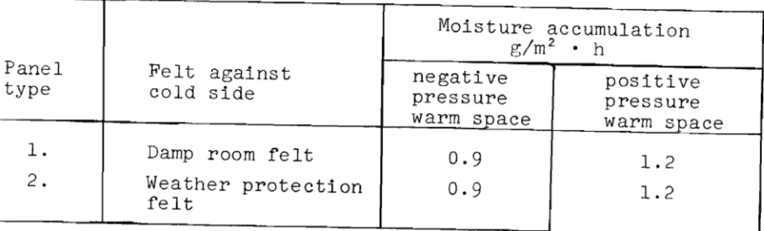
Two different types of felt, namely damp-proof felt and weather protection felt, were tested. Table II shows the moisture accumu-lation with positive and negative pressures on the warm side. The felt against the warm side was weather protection felt.
During the period when the pressure in the heated space was negative, the moisture accumulation was 0.9 g/m2 • h, while during the period when the pressure in the heated space was positive, it was 1.2 g/m2 • h for both types of felt.
Under the aforementioned climatic conditions in the cooling room (7150C), there is no significant difference in the moisture accumulation when either type of felt is used on the cold side of the wall. With other temperature conditions on the cold side, the relationship will change. Felt against the cold side also has a considerable effect on the drying out of the panels. The イ・ウオャエウセ
エィ・イ・ヲッイ・セ must in no way be interpreted to mean that in practiae the density of the exterior felt is unimportant.
A negative pressure in a heated room causes a current of cold, dry air to pass through the wall. Under the pressure, temperature and moisture conditions which were investigated in this case, the air current did not result in the elimination of any appreciable part of the moisture whiah entered the wall by diffusion through the weather proteation felt. A positive pressure on the warm side produced an increase in moisture accumulation of
0.3
g/m2• h, or
approximately
50%,
when weather protection felt was used.On account of this high moisture accumulation in the panels containing weather protection felt on the cold side, three panels, which were very permeable (to diffusion) were also tested in the second test period when a positive pressure was applied to the
During the period when the warm side was exposed to a positive pressure there were comparatively large variations among individual
panels owing to unintentional air leakages. The types of structure
appearing as items 1, 2 and 3 of the table were tested in only one
panel each. Therefore, the results should be regarded as a guide
only.
The panel without felt on the cold side and the panel with
unimpregnated felt both show a high degree of moisture accumulation. The moisture settled on the panel as ice and frost and gradually
accumulated towards the interior of the insulating material. Where
the moisture formation in the open structure panels on the cold side is greater than in the comparatively dense panels, this may
be connected with the fact that the passage of air has also increased. During the period when the pressure on the warm side is positive,
the moisture formation will increase in proportion to the increase
in the passage of air. Even if the number of panels is small, the
tests show clearly that at temperatures of +l50C or less on the
cold side, the exterior panel alone is enough to produce moisture
accumulation in the walls under the given test conditions.
c. The effect of different types of felt on the warm side of the
wall
Two different types of felt, namely damp-proof felt and weather
protection felt, were tested on the warm side. Weather protection
felt was placed on the cold side.
Table IV shows the moisture accumulation with negative and positive pressures on the warm side.
In all cases, moisture accumulation was greatest in panels
with weather protection felt on the warm side. It was at least of
the order of 1.0 g/m2 • h. According to observations made in the
exterior wall panels around the climate laboratory, i t is estimated that the moisture will begin to run down along the felt when the
level of deposition reaches approximately 100 g/m2 • The wooden
struc-tures will then be gradually saturated with moisture. If a moisture
accumulation of 100 g/m2 is taken as the maximum in this type of
with weather protection felt on the warm side, a temperature of
7150C on the cold side, and a temperature of +150C and relative
humidity of
85%
on the warm side.With damp-proof felt and a negative pressure (0.4 mm water
gauge) on the warm side, the moisture accumulation is very small
and of no practical significance. When the panels were opened,
they appeared to be absolutely dry. On the other hand, with a
positive pressure on the warm side, a considerable amount of moisture
also accumulates in the panels which have damp-proof felt on the
warm side and weather protection felt on the cold side. Figure
7
shows ice and frost formation in a pair of test panels at the end of the period when a positive pressure was applied in the heated
space. The panel to the left has weather protection felt on the
warm side, and the panel to the right has damp-proof felt.
It was only in those panels which had damp-proof felt against
the Warm side and when the pressure in the heated space was above that of the cold space that the moisture accumulation in the wall panels came within satisfactory limits.
3.
The effect of pressure conditions on the moisture accumulationin the floor panels
The floor in the cooling room is raised approximately 180 em above the floor of the surrounding room so that warm, moist air
can circulate under it (Figure 1). The floor is made of
8"
planksand insulated with 10 ern of mineral wool. Different types of felt
are laid against the warm and cold sides, in a manner similar to
that used in the wall panel tests. A 10 ern air space is left between
the inSUlating material and the cold felt in the floor panels. The pressure conditions across the floor panel were somewhat
different from the average for the wall panels. Cold air being
heavier than warm air, when the pressure on the warm side is negative the indicated pressure difference will be increased by approximately
0.15 mm (water gauge). With a positive pressure on the warm side
there will be a corresponding reduction in the pressure difference. Therefore, for floor panels, we can estimate that during the period when the pressure on the warm side is negative there will be an
averaGe pressure difference of approximately 0.55 mm (water gauge), while during the period when the pressure on the warm side is positive
there will be an average pressure difference of approximately 0.35 mm (water gauge).
Table V shows the moisture accumulation in the floor panels with negative and positive pressures on the warm side.
The floor panels in the cooling room have the warm side
under-neath and the cold side on top. During the period when the pressure
on the warm side is positive, the conditions will, in principle, correspond to those obtaining in the floors between heated space and loft, flat roof without a loft, and the like.
During the period when the pressure on the warm side was
neg-ative, there was never any moisture accumulation of significance.
This may be due to the fact that the moisture which had spread in through the felt on the warm side and into the cavity was carried
out again by an air current in the opposite direction. This gives
us reason to assume that the air current between the insulating material and the cold felt has a favourable effect in this respect. Moreover, the passage of air in the floor panels was probably greater than in the wall panels on account of accidental leakages.
When the pressure on the warm side is positive, the moisture
accumulation on the floor surfaces is very great: 2 - 3 g/m2 • h.
If the maximum permissible moisture accumulation in this case is
also set at 100 g/m2 , this level will be reached in the course of
30 - 50 hours, i.e., 1 - 2 days. At the end of the test period,
in the course of 140 days, 9 - 14 kg of water per m2 accumulated
in the form of frost and ice in the floor panels. The felt against
the cold side was covered by a thick layer of frost and ice (Figures
8
and9)
and in a few of the panels the cavity was partly filledas well.
The types of felt on the warm and cold sides had little effect
on the moisture accumulation. The panel with damp-proof felt
against the warm side had slightly less moisture accumulation than the other panels, but moisture migration by air currents undoubtedly
out at a temperature of 7150C on the cold side. At higher temper-atures, the type of felt against the cold side is more important.
When the moisture accumulation in these panels during the period of positive pressure in the heated space is this great, it may be due to unintentional leakages at the intersection of floor and wall, or faulty clamping of the felt joints onto the beams. Insofar as the workmanship was concerned, this was done with as much care as in the case of the wall panels and as well as could
be expected in normal practice. There is reason to assume that
the air leakages at the intersection of floor and wall quickly worsen when a joint is formed between the felt in the wall and the
felt in the floor. In the floor panels of the cooling room, the
effect of this joint will be greater than under the conditions usually encountered in practice, since all the floor panels butt
against the wall panels on one or two sides. This also agrees
with the previously cited studies of Granum, Svendsen and Tveit
(1954), which show a considerable decrease in the amount of air
passing through wall panels with penetrating floor joists. In
heated houses, barns, or industrial bUildings, there is often a positive pressure on the warm side, the cold side being on top,
as in this test. There are, therefore, grounds for considerable
concern over the installation of felt in the roof of such bUildings,
especially i f there is a high moisture content in the air. 'I'he
best guarantee against harmful effects of this nature is obtained by maintaining the pressure on the warm side slightly below the
pressure on the cold side, for example, by taking in cold air
through the ceiling of such bUildings.
4.
Moisture distribution in the wall panelsAt the end of each test period, the thickness of the ice
for-mation was measured at different points. Ice formed on the cold
felt only, except in isolated cases where stray air currents caused by excess pressure on the warm side had been disproportionately
large. Gradually, as the frost and ice layer increased in thickness,
a. Pattern of the vapour pressure curve
Figure 10 shows the temperature, the saturation pressure and the calculated vapour pressure across one of the wall panels of
the climate laboratory with weather protection felt on both sides.
As shown on the chart, the calculated vapour pressure curve is higher than the saturation pressure curve for the whole of the
outer half of the wall panels. Nowhere is the actual vapour pressure
higher than the saturation pressure. That is to say, the saturation
pressure in the boundary layer between the insulating material and the felt on the cold side is decisive for the pattern of the vapour pressure curve.
The drop in vapour pressure in each individual layer of the wall is proportional to the vapour resistance in the same layer. Therefore, in determining the actual vapour pressure curve for this structure, it is necessary to take a starting point on the interior vapour pressure and the calculated saturation pressure
on the exterior felt. The vapour pressure curve is easily
con-structed according to the above-mentioned priciples. The actual
vapour pressure curve is shown as a dotted line in Figure 10. viith
this shape of vapour pressure curve it is clear that moisture
for-mation can occur only on cold felt. Moisture will only occur
in-side the insulating material when it builds up from the cold in-side. The displacement of the actual vapour pressure curve in relation to the originally estimated curve is also important for calculating
the amount of moisture which diffuses into the wall. The amount of
diffused water vapour is proportional to the pressure drop across
the layer. On account of the displacement of the vapour pressure
curve, the actual vapour pressure on the interior felt in this
case is
5.4
mm Hg, as opposed to the originally calculated 3.0 mm.The quantity of vapour which diffuses into the wall will for this reason be apprOXimately 80% higher in this case than is indicated
by calculation methods which are sometimes used. The relative
humidity on the cavity side of the felt against the heated space will also be very low on account of the shape of the vapour pressure curve.
If the saturation pressure is consistently above the calculated vapour pressure, no displacement of the vapour pressure curve will occur at all.
b. Distribution of deposited ice
Figure 11 illustrates the ice formation in panels with weather
protection felt on both sides (type 2) at the end of the period
during which the pressure on the warm side was negative. Panels
139 and 149 were not ventilated, while panels 144 and 153 have a
10 cm wide open slit on top. As shown in Figure 11, there is
relatively little variation in the thickness of the ice layer, which
usually reaches a maximum about
5
cm from the supports and decreasessomewhat towards the centre and out towards the supports. The
thick-ness of the ice layer for practical purposes is considered normal
up to 1 - 2 cm from the opening in the ventilated wall panels. In
this test the insulating material did not have a lO cm wide, complete10
open slit in it; the felt and panel against the cold side had a
meas-urable influence on the moisture formation at a greater distance than
5 cm from the opening. This method of preventing condensation in
the cooling room walls must therefore be considered unsuitable. During the period when pressure on the warm side was positive, the moisture formation took a somewhat different form from that
observed during the period when the pressure was negative. Figure
12 shows the thickness of the ice layer for the panels shown in Figure 11 at the end of the period when pressure on the warm side was positive.
In this case, the moisture formation is much more uneven than
in the preceding period. The positive pressure on the warm side
has resulted in warm moist air permeating through unintentional openings into the structures, and the condensation of moisture in the vicinity of those places where leakage has occured.
D. The Effect of Pressure Ratios on Condensation and Moisture Migration under Conditions Encountered in Practice
Systematic investigations of the effect of pressure conditions on moisture migration and condensation encountered in practice rlave
not been carried out previously. Finne (1959) mentions several
cases of heavy condensation formation mainly attributable to moisture migration by air currents in industrial building structures and the like.
On investigating the durability and upkeep of wooden structures in a large number of barns, a clear relationship was established
between ventilation and structural durability. In addition to
elim-inating moisture, ventilation also causes a negative pressure in the
room. In this way warm moist air is prevented from seeping into the
structures. This explains why the floor of a barn with penetrating
beams is especially subject to damage. Figure 13 shows how fresh
air has streamed in through cracks at the intersection of wall and
ceiling and in a wall corner. The barn was well ventilated and the
negative pressure under the roof was approximately 0.2 mm (water
gauge). If the barn had been unventilated, the air stream would
have gone in the opposite direction and caused condensation to form
on the cold side. Figure 14 shows how the wall stud has rotted at
the intersection of the wall and vaulted roof of a cow barn. The
part above the wall is covered with ice and frost from condensed
water vapour. If the wooden roof is put on without felt, a large
amount of moist air could escape through the cracks. Some of the
moisture would penetrate the insulating material, which would then become saturated (Figure 15).
Large cracks, for example around leaky hatches and the like, could result in the upward displacement and condensation of large
quantities of moist air. Figure 16 shows frost formation above
the fore-hatch of the barn, and Figure 17 shows frost formation towards the centre of the loft.
Figure 18 shows ice on the eaves of a barrack which formed as a result of warm moist air seeping out through cracks, the moisture condensing on the eaves, etc.
Condensation between the panes of double windows in a
farm-house is often caused by air currents. Under conditions which
produce a higher pressure on the warm side than the pressure of the outside air, the air between the panes will leak out and
mois-ture will settle on the outside window pane. Experience shows that
in a 2-storey house, for example, which has an open stairway between
the first and second floors, condensation is more prevalent on the
second floor. Furthermore, it is apparent that condensation will
occur primarily on the lee side of the house.
E. Summary
Experience in practice has shown that our present knowledge of the patterns of moisture migration in bUilding structures does not provide an adequate theoretical basis for the calculation of
moisture conditions. One of the reasons for this is that, in
addi-tion to diffusion and capillary sucaddi-tion, moisture can be transported
by random air currents. This factor has not been taken into account
in calculations.
The significance of air currents for moisture transportation in wood frame structures is studied in a climate laboratory at
the Norwegian Agricultural College. The tests are carried out both
on felt samples and full scale structures. The temperature on the
warm side is
+15
0C and the relative humidity85%.
The temperatureon the cold side is +150C. Thus, the test conditions correspond
to those obtaining in a room with high humidity when the outside temperature is low.
The tests show that air currents can carry large quantities
of moisture, which penetrate the structures. Particularly large
quantities of moisture are found in the floors. Damp-proof feZt
on the warm side is not sufficient to prevent moisture formation
under the given test conditions3 i f at the same time the atmospheric
pressure on the warm side is not slightly negative. The type of
felt on the cold side, under the above temperature conditions, did not have any appreciable effect on the moisture formation; neither
did a 10 em wide opening at the top of the wall panels have any significant effect on moisture accumulation.
References
1. Babbitt, J. D. The Physics of Condensation in Buildings.
National Research Council, Bul. No.2, 1952.
2. Cammerer, W. F. and Durhamrner, W. Die Berechnung der
Darnpdiffusions- Vorgange im Baulichen Warme- und Kalteschutz und die dafur zwecksmassigsten
Mess-und Rechnungsgrossen. Gesundheits Ingenieur.
Heft 19/20, 1950.
3. Dick, J. B. Roof condensation in an air-conditioned
factory. J.I.H.V.E. 21, 1954.
4. Edenholm, H. FUktighetsvandring och fuktighetsfordelning
i byggnadsvaggar (Moisture migration and moisture
distribution in the walls of buildings).
Medd. Statens forskningskommitte for Lantmannabyggnader nr. 5. Kap IV, Lund, 1945.
5. Finne, Eirik Kondens i yttervegger (Condensation in
exterior walls). Bygg nr. 4, 1959.
6. Finne, Eirik Kondensteknisk uheldige konstruksjoner
(Unfavourable structures from the point of view of
condensation characteristics). Bygg nr. 9, 1959.
7. Flachsbart, O. Winddruck auf geschlossene und offene Gebaude.
Ergebnisse der Aeoradynarnischen Versuchsanstalt zu Gottingen, Lieferung 4, 1932.
8.
Granum, H., Svendsen, S. D. and Tveit, A. Lette treveggersvindtetthet (Wind resistance of light-weight wooden
walls), Norges byggforskningsinstitutt, report nr. 7,
Oslo, 1954.
9. Granum, Hans Kondensproblemer i hus (Condensation problems
in the house). Bygg nr 2, 1953.
10. Hanson, R. Fukt i yttervaggar och yttertak (Moisture in
exterior walls and roof). Byggmasteren nr. B 10, 1957,
nr. B 12, 1957, nr. B 1, 1958 and nr. B 3, 1958.
11. Irminger, J. O. V. and nセォォ・ョエカ・、L C. Vindtrykk pg byggninger
(Wind pressure on bUildings). iョァ・ョゥセイカゥ、・ョウォ。「・ャゥァ・
skrifter nr. 24, kセ「・ョィ。カョL 1936.
12. Johanson, C. H. and Persson, G. Berakning av fUktfordelning
och fUktvandring i yttervaggar (Estimating moisture
distribution and moi§ture migration in exterior walls).
Teknisk Tidsskrift, Arg. 79, 1949.
13. Joy, F. A. and Fairbanks, D. R. Effect of unbalanced air
pressure on permeance. Heating, Piping and Air
14. Joy, F. A., Queer, E. R. and Schreiner, R. E. Water Vapor
Transfer through Building Materials. Pennsylvania
State College, Eng. Exp. Station Bul. 61.
15. Krischer, 0., Wissman, W. and Kart, W.
Feuchtigkeitsinnwirk-ung auf Baustoffe aus der umgebenen Luft. Gesundheits
Ingenieur (79), Heft 5, 1958.
16. Raiss, Wilhelm H. Rietschels Lehrbuch der Heiz- und
Luftung-stechnik, Berlin 1958.
17. Rowley, F. B., Algren, Axel B., Lund, Clarence E. Condensation
of moisture and its relation to building construction and
operation. University of Minnesota. Eng. Station, Bul.
no. 18. Minneapolis 1941.
18. Torp, aウ「ェセイョ Om kondensasjon i vegger rundt husdyrrom
(Concerning condensation in barn walls). Norsk
Landbruk nr. 20 and 21, 1950.
19. Torp, A. and Graee, T. kッョカ・ォウェッョウウエイセュョゥョァ・イ i
isolasjons-materialer (Convection currents in insulating materials).
Bygg nr. 8, 1956.
20. Tveit, A. Vanndampdiffusjonstall for papp og trefiberplater
(Water vapour diffusion values for felt and wood
fibre-boards). Norges oyggforskn. institutt. Report nr. 9,
1954.
21. Watzinger, A. Die Feuchtigkeitswanderung in isolierten
Table I
MOisture accumulation in grams per m2 per hour
(g/m2 • h) for ventilated and unventilated wall
panels with negative pressure against the warm side of the walls
Moisture accumulation Panel g/m2
.
h Difference Type Ventilated Unventilated g/m2.
h Panel Panel 1. 1.0 0.7 0.3 2. 1.0 0.9 0.1 3. 0.04 0.03 0.01 Table IIMoisture accumulation in wall panels with different types of felt on the cold side
of the wall. The felt against the warm
side was weather protection felt
Moisture accumulation
g/m2
.
hPanel Felt against negative
positive
type cold side pressure
pressure
warm space warm space
1. Damp room felt 0.9
1.2
2. Weather protection 0.9
1.2 felt
Table III
Moisture accumulation in wall panels with dissimilar density on the cold
side. Weather protection felt against
warm side. Positive pressure in
heated space
Structure, cold side
1. No felt, panel only
2. Unimpregnated felt, panel
3.
Asphalt glued impregnatedporous wood fibreboard and panel
4.
Weather protection feltand panel
5.
Damp-proof felt and panelTable IV Moisture accumulation g/m2 • h 1.8
1.5
1.0 1.2 1.2Moisture accumulation with different types of felt on the warm side of the
wall. Weather protection felt against
the cold side
Moisture accumulation
g/m2
.
hPanel, Felt against warm
type side Positive Pressure, Negative Pressure,
heated space heated space
2. Weather protection 0.9 1.2
felt
Table V
Moisture accumulation in the floor panels with negative and positive pressures on the warm side
Moisture accumulation
g/m2
.
hPanel, Felt, warm side Felt, cold side
Negative Positive
type
pressure, pressure,
warm, side warm, side
l . Wea.ther protec-Damp-proof felt 0.0 3.4 tion felt 2. Weather protec-Weather protec- 0.0 3.4
tion felt tion felt
3. Damp-proof felt
Weather protec- 0.0
2.6 tion felt
s
Fig. 1
Climate laboratory and Norwegian Building Research Institute's house for condensation research
1. Refrigeration plant
2. Refrigeration unit, upper part removed
3.
Ventilators for regulating air pressure4.
Exterior test panels5.
Gangway6. Space containing warm moist air
7.
Interior test panels8.
Refrigerated space - two panels removed9. Water evaporator
10. Heating unit
Wind セ
Section
wゥョ、セ
Fig. 2
Pressure conditions around an enclosed bUilding exposed to wind (Flachsbart)
0.15
mm\0.15
mm w.g. negative internal pressureFig.
3
Pressure conditions in a heated room with the neutral layer at haJf the room height
U} Cl> >< (".J...., Pres sure re g. ッセセイG b :
HlN]Zsセyセセpッウゥエゥカ・
U) ( jセBゥSョ・ァ。エゥカ・ Cl> E-; Layout ヲイoュセエセ aboveセpイ・ウウオイ・
Hose , 1 _'IV r-eg. room
Test box Box for drying
air for press. reg. Layout from side
Fig.
4
Experimental layout for testing the effect of pressure conditions
on vapour diffusion through felt
unctured axes npunctured axes P
/b
/
/
V
0/
/
,
1/
..
u
セセ
セM b セNNMMM ',,-. 1 lD 10"'1 .1JI tQI ,1,1 -\D Press. in box, mm w.g. Wt.inc.mg. fJO Fig.5
Average weight increase in mg per hour for punctured and unpunctured boxes
Fig.
6
Wall panel structures with
without lation
Fig.
7
Moisture accumulation in panel with weather protection felt (left) and panel with damp-proof felt (right) on warm side.,
Te::lpo ra tun:
°c
-r-r
' i ;.:&=1]1
1
1 : -MAiᄋセ
I;;
- H ' - - - ;:-
エセョ i I'" 3/".PFLnel--':-=:"':=-,i
-1:---1_.
-r':
Weather protectiOll fcltf--l=i1-=-:1:r:::=_l:;
10 em llli::.er;:d 101001セNャ]ZエZMM I
I
t
\lcather prQtectic.n felt=-
:j:-===
---:j:- .·Zセ セ I , - - 't-1---1.tD
"'·,.ne1
=til: -- ---
サセMセM
Zセ
- -1,-
----ii/-
1- -- -
'0Kゥセ
_uNiセ
セャ
gn
- r-;
Nセ
.,;
Vapour pressure. CUll Hg' I
:jf1J
13セ ,t LNMセセ Saturation pressure IZセ - ---i' ..h _ . _ _ . _
'--J1,J--, 1[' - , I II . ' - - GZMMMMMMMセMセMc。ャ」オャFエャG、 vapour pressure I0セMMMMlIi:
.
オスセZQLᆪ CUrTe 9セMMMMQ:':
MMMMセM MOセA I iActual vapour , I ' I 1.I I eセMMQZGMGMMMイMMG セ pressure CUM'eセエ]iMMセO
5'---
1,--1ャセM
" L __[セ
セ[iG
: -I-3-' I " " ,-;i----tf ---
=it
Fig. 10Temperature, saturation pressure and vapour pressure across wall panels
Panel/32 Panel 144 Panel 142 Panell53
I ID ID
Fig. 11
Thickness of ice formation in mm of four cooling room wall panels at end of period during Which
warm side was exposed to negative pressure. Weather protection felt on both sides
Fig. 12
Thickness of ice formation in mm of four cooling room wall panels at end of period during Which
warm side was exposed to positive pressure. Weather protection felt on both sides
leaks
in corner at intersection
of roof and walls of well-Fig.
15
Frozen sawdust and rotten beam in stab le ceiling.
No felt and poor ventilation
-above a leaky fore-hatch in an unventilated barn