Abstract—LiNi0.5Mn1.5O4 thin films have been grown by
pulsed laser deposition (PLD) on stainless steel (SS) substrates. The crystallinity and structure of thin films were investigated by X-ray diffraction (XRD). The microstructure and surface morphology of thin films were examined using a field-emission scanning electron microscope (FESEM). The electrochemical properties of the thin films were studied with cyclic voltammetry (CV) and galvanostatic charge-discharge in the potential range between 3.0 and 4.9 V. The electrochemical behavior of LiNi0.5Mn1.5O4 thin films showed
reversible capacity above 4.7 V and good cycle performance up to 50 cycles.
Keywords—Cathode; LiNi0.5Mn1.5O4; Pulsed laser
deposition; Thin film batteries
I. INTRODUCTION
AYERED LiCoO2, LiNO2 and spinel LiMn2O4 are the
most important cathode materials for Li-ion batteries because of their high voltage (4 V vs. Li/Li+) and good cycleability. Among them, the spinel LiMn2O4 is the most
favored one due to its lower cost and toxicity [1-3]. However, LiMn2O4 is not stable during cycling especially
at elevated temperature, which results in a rapid capacity fade and limits its practical use [4-6]. Therefore, much research has been performed to improve its charge and discharge cycle performance.
One excellent method for improving the cycle performance has been the substitution of other transition metals for Mn to make LiMxMn2-xO4 (M = Co [7], Cr [8],
Ni [9], Fe [10], Cu [11], etc.). Interestingly, it has been found that this approach is also accompanied by a higher voltage plateau at about 5 V as a result of the redox system provided by the transition metal substituted. These materials are now attractive candidates as cathode materials for lithium-ion batteries, because they can increase the cell voltage to 5 V from the present 4 V. Among these materials, LiNi0.5Mn1.5O4 is the most attractive material for
the practical preparation of 5 V cathodes due to its good stability on repeated Li-ion extraction and insertion [12-14].
Thin film lithium batteries now are attracting more and more interest. It is an interesting research field, not only because miniaturization of electronic devices makes it possible to use thin film microbatteries as power sources, but also because the thin film electrode without any polymeric binder and carbon black is perfect sample to investigate the electrochemical properties of the material. As for the thin film cathodes, LiCoO2, LiNiO2 and
LiMn2O4 are fully researched using different deposition
methods. However, few papers have been published for this 5 V thin film cathode [15, 16] due to the novelty of this type of cathode materials.
The aim of this work is to prepare thin films of LiNi0.5Mn1.5O4 on SS substrates by pulsed laser deposition.
The structure and microstructure of thin films were measured by XRD and FESEM. Electrochemical properties of the thin film cathodes were investigated by CV and charge-discharge cycling test. Two high voltage plateaus at about 4.7 V were observed on both charge-discharge voltage profiles. The Li/LiNi0.5Mn1.5O4 cell showed very
good cycle performance for 50 cycles. II. EXPERIMENTAL A. Thin Film deposition
LiNi0.5Mn1.5O4 target was prepared by a solid-state
reaction using MnO2 99.9% (Alfa Aeser), NiO 99% (Alfa
Aeser) and LiOH 98% (Merck). The mixture powders were reacted at 750°C for 24 h, then pressed into a pellet and sintered at 900°C for 2 h. Target and stainless steel substrates were placed inside a vacuum chamber with a turbo-molecular pump yielding a pressure less than 1 × 10⁻⁵ Torr. The target-substrate distance was kept at 40mm. During deposition, the target is rotated at 10 to 20 rpm to avoid depletion of material at any given spot. A Lambda Physik KrF excimer laser beam (λ = 248nm, pulse width = 25ns, laser energy = 150-160 mJ/pulse) was incident on the target at an angle close to 45° at a repetition rate of 10 Hz. The focused spot size is 2 × 5 mm at the target resulting in a laser fluence of 2 J/cm2. Films deposition was carried out at a substrate temperature of 600°C in an oxygen
Characterization of LiNi
0.5
Mn
1.5
O
4
Thin Film
Cathode Prepared by Pulsed Laser Deposition
Hui XIA
1, Li LU
1, 2, and Gerbrand CEDER
1, 31
Singapore-MIT Alliance, E4-04-01, 4 Engineering Drive 3, Singapore
2
Department of Mechanical Engineering, National University of Singapore, Singapore 119260
3
Department of Material Science and Engineering, Massachusetts Institute of Technology,
Cambridge, Massachusetts 02139
atmosphere of 100mTorr for 40 min. The amount of LiNi0.5Mn1.5O4 was estimated by weighing the electrode
substrate before and after the film deposition using a microbalance (A&D, GR-202).
B. Microstructure Analysis
Structure and crystallinity of thin films were measured by a Shimadzu XRD-6000 X-ray diffractometer with Cu Kα radiation. The data were collected in the 2θ range of 10-70° at a scan rate of 2° per min. Surface morphology of thin films was characterized using a Hitachi S-4100 Field Emission Scanning electron microscope (FESEM).
C. Electrochemical Measurements
Electrochemical measurements were carried out on Li/LiNi0.5Mn1.5O2 cells using the LiNi0.5Mn1.5O2 thin film as
cathode and a lithium metal foil as both anode and the reference voltage electrode. All experiments were conducted in an Ar-filled glove box with the H2O and O2
levels less than 0.1 ppm. A Solartron 1287 two terminal cell test system was used to perform all electrochemical measurements. The electrolyte solution was 1 M LiFP6 in a
1:1 (by volume) ethylene carbonate (EC)-diethylene carbonate (DEC) solution. Cyclic voltammetry was carried out between 3.5 and 5 V versus Li/Li+ at a slow sweep rate of 0.2 mV s-1. Galvanostatic charge-discharge cycling test was carried out in the potential range between 3.0 and 4.9 V using a constant current density of 20 µA/cm2.
III. RESULTS AND DISCUSSION
The crystal structure of the synthesized LiNi0.5Mn1.5O4
powder and deposited LiNi0.5Mn1.5O4 thin film on SS
substrate were investigated by XRD in Fig.1. From the XRD spectrum of the synthesized powder, we can see the calcination of mixture at 750 for 24 h provided us a single phase of LiNi0.5Mn1.5O4. All peaks appeared in the XRD
spectrum of LiNi0.5Mn1.5O4 powder are very sharp,
indicating a high crystallinity of the powder. The Miller index for each peak was determined based on a spinel structure having
Fd3
m
space group. From the XRD spectrum of LiNi0.5Mn1.5O4 film on SS substrate, only threepeaks are identified as (111), (311) and (222) reflections from LiNi0.5Mn1.5O4 thin film. Among these reflections,
(111) is the strongest one just as the XRD spectrum of LiNi0.5Mn1.5O4 powder. However, very weak peaks from
other reflections mean the film is mainly (111) texture. No impurity phase was observed from the XRD spectrum of LiNi0.5Mn1.5O4 film deposited on SS substrate.
The surface morphology and crystal shape of the spinel LiNi0.5Mn1.5O4 thin film deposited on SS substrate at 600°C
was investigated using the FESEM. Fig. 2 shows two FESEM images of LiNi0.5Mn1.5O4 thin film with low
magnification and high magnification, respectively. From Fig. 2 (a), it can be seen that the film is very dense without any crack or pinhole. However, the film is not very smooth
due to some big droplets clustered on the surface. From Fig.2 (a), it can be seen that the average grain size is about 100-200 nm and grains exhibit polyhedral shapes, which
(a)
(b)
Fig. 2. FESEM images for LiNi0.5Mn1.5O4 thin film deposited on SS
substrate at 600°C, (a) image with low magnification (b) image with high magnification.
Fig. 1. XRD θ/2θ spectra for the synthesized LiNi0.5Mn1.5O4 powder
are usually observed in cubic crystal system. The XRD and FESEM results showed that a well-crystallized and highly dense LiNi0.5Mn1.5O4 thin film was successfully prepared by
PLD. The advantage of PLD to produce high quality oxide thin films was also proved by our previous research of LiCoO2 thin films by PLD.
Fig. 3 displays a typic cyclic voltammogram of a LiNi0.5Mn1.5O4 thin film cathode cycled between 3.5 and 5
V vs. Li/Li+ at a slow sweep rate of 0.2 mVs-1 in the LiPF6/EC-DEC electrolyte. As shown in Fig. 3, there pairs
of peaks were observed with two pairs of strong peaks at high voltages about 4.7 V and one pair of weak peaks at about 4 V. The high voltage peaks at 4.68 (A1) and 4.79 V (A2) on anodic scan, and at 4.65 (C1) and 4.75 V (C2) on cathodic scan correspond to the redox reactions of Ni2+/Ni3+ and Ni3+/Ni 4+ according to references [12, 13]. Dahn et al. [12] suggested that the electrode potential of LiMn2O4 can be enhanced from 4.1 to 4.7 V by a
substitution of a part of Mn ions in LiMn2O4. They have
discussed an appearance of the 4.7 V electrode potential region by using UV photoelectron spectroscopy and have claimed that an energy of 3d level for Ni2+ ion and Ni3+ ion in a low spin state is lower than that of Mn3+ ion in a high spin state. Such a difference between energies for 3d levels leads to a higher electrode potential of LiNi0.5Mn1.5O4.
However, the presence of peaks at about 4 V, corresponding to a redox reaction of Mn3+/Mn4+, suggests that the film may be nickel deficient. Dahn et al. [12] also suggested that the Ni deficiency in their LiNi0.5Mn1.5O4
powder was due to the oxygen loss in their samples heated above 650°C. In our case, there is probably some Ni loss during the high temperature material synthesis and high vacuum deposition process. LiNi0.5Mn1.5O4 thin film was
also prepared by Mohamedi et al. by electrostatic spray deposition (EDS) using a precursor solution. No redox couple at 4 V was seen in their CV result, which means their spinel film has desired Ni content.
To investigate the battery performance of this thin film cathode, 50 charge/discharge cycles of a lithium battery employing LiNi0.5Mn1.5O4 thin film cathode were
performed between 3 and 4.9 V at a constant current of 20 µAcm-2. The charge/discharge voltage profiles at 1, 10, 20, 30, 40 and 50 cycles were shown in Fig. 4. As expected from the CV results, three plateaus were observed on both charge/discharge curves. The small plateau at about 4 V corresponds to the redox reaction of Mn3+/Mn4+, while the two big plateaus at about 4.7 V correspond to the redox reactions of Ni2+/Ni3+ and Ni3+/Ni 4+. Except for the first cycle, charge and discharge are highly reversible for the subsequent cycles. There is no obvious electrolyte decomposition reaction observed in the charge process at high voltage near 5 V, which is very obvious for LiCoO2
thin film cathode. There is only a small difference between the voltage plateaus of charge and discharge, which means the Li/LiNi0.5Mn1.5O4 cell has a small polarization. It also
can be seen that these voltage plateaus for both charge and discharge don’t change much even at the 50th cycle, which means the cell resistance doesn’t change much with cycling. Fig. 3. Cyclic voltammogram of the LiNi0.5Mn1.5O4 thin film cathode
cycled between 3.5 and 5 V vs. Li/Li+ at a sweep rate of 0.2 mVs-1 in LiPF6/EC-DEC electrolyte.
Fig. 4. Charge/Discharge voltage curves of LiNi0.5Mn1.5O4 as a 5 V
cathode material investigated in the potential range 3.0 – 4.9 V vs. Li/Li+ with a constant current of 20 µAcm-2.
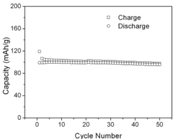
Fig. 5. Cycle performance of the LiNi0.5Mn1.5O4 thin film cathode
cycled between 3.0 and 4.9 V vs. Li/Li+ at a constant current of 20
µAcm-2 in LiPF
The theoretical capacity of LiNi0.5Mn1.5O4 is calculated to
be 146.6 mAhg-1 when all Li+ ions can be extracted from this material. In our test, the first charge capacity is about 120 mAhg-1, after that, a reversible capacity about 100 mAhg-1 is maintained. The utilization of the film calculated from the first charge is about 80%. The correctness of this calculation could be affected by the weighing of the thin film. The charge/discharge capacities vs. cycle number were shown in Fig. 5. The Li/LiNi0.5Mn1.5O4 cell showed a
very good cycle performance for 50 cycles. The discharge capacity fades with a small rate of about 0.06% per cycle, which is similar to the result of Kanamura et al. [13]using a composite electrode but better than the result of Mohamedi et al. [15] also using a thin film electrode prepared by ESD. Except for the first several cycles, the coulombic efficiency is as high as 98%.
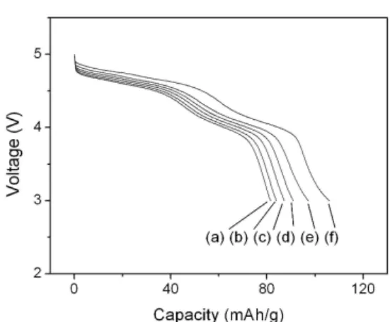
Fig. 6 shows the discharge curves of a Li/LiNi0.5Mn1.5O4
cell at different current densities, which was used to test the rate-capability of the cell. As the current density is increased, the cell voltage is lowered and the useful capacity of the cell is decreased. This is mainly due to the cell resistance which increases the cell polarization as the current density increases. The largest contributions to the battery resistance are lithium-ion transport into and through the cathode.
IV. CONCLUSION
LiNi0.5Mn1.5O4 thin film cathode as a promising
candidate for 5 V cathode materials of lithium batteries were successfully prepared by PLD. The CV results showed two pair of peaks at about 4.7 V corresponding to the two redox reactions of Ni2+/Ni3+ and Ni3+/Ni 4+. The presence of peaks at 4 V means that the film is a little bit deficient of Ni which results in some Mn3+ in the film. The LiNi0.5Mn1.5O4 thin film cathode showed excellent cycle
performance between 3 and 4.9 V, exhibiting a stable and highly reversible capacity of about 100 mAhg-1 for 50 cycles.
ACKNOWLEDGMENT
This research was supported by Advanced Materials for Micro- and Nano- System (AMM&NS) programme under Singapore-MIT Alliance (SMA) and by National University of Singapore. We would like to thank Dr. Y. S. Meng from the department of Materials Science and Engineering, Massachusetts Institute of Technology, Cambridge and Dr. Songbai Tang from the department of Mechanical Engineering, National University of Singapore for useful discussions.
REFERENCES
[1] D. G. Wickham, and W. J. Croft, “Crystallographic and magnetic properties of several spinels containing trivalent ja-1044 manganese,” J. Phys. Chem. Solids, vol. 7, pp. 351–360, 1958.
[2] M. M. Thackeray, W. I. F. David, P. G. Bruce, and J. B. Goodenough, “Lithium insertion into manganese spinels,” Mater. Res. Bull., vol. 18, pp. 461–472, 1983.
[3] J. M. Tarascon, and D. Guyomard, “The Li1+xMn2O4/C rocking-chair system: a review,” Electrochim. Acta, vol. 38, pp. 1221-1231, 1993.
[4] R. J. Gummow, A. de Kock, and M. M. Thackeray, “Improved capacity retention in rechargeable 4 V lithium/lithium-manganese oxide (spinel) cells,” Solid State Ionics, Vol. 69, pp. 59–67, 1994. [5] X. Sun, H. S. Lee, X. Q. Yang, and J. McBreen, “Improved
elevated temperature cycling of LiMn2O4 spinel through the use of
a composite LiF-based electrolyte,” Electrochem. Solid-State Lett., Vol. 4, pp. A184–.A186, 2001.
[6] S. J. Wen, T. J. Richardson, L. Ma, K. A. Striebel, P. N. Ross Jr, and E. J. Cairns, “FTIR spectroscopy of metal oxide insertion electrodes A new diagnostic tool for analysis of capacity fading in secondary Li/LiMn2O4 cells,” J. Electrochem. Soc., Vol. 143, pp. L136–L138,
1996.
[7] H. Kawai, M. Nagata, H. Kageyama, H. Tukamoto, and A.R. West, “5 V lithium cathodes based on spinel solid solutions Li2Co1+xMn 3-Xo8: -1<X<1,” Electrochim. Acta, Vol. 45, pp. 315–327, 1999.
[8] C. Sigala, D. Guyomard, A. Verbaere, Y. Piffard, and M. Tournoux, “
Positive electrode materials with high operating voltage for lithium batteries: LiCryMn2-yO4,” Solid State Ionics, Vol. 81, pp. 167–170,
1995.
[9] K. Amine, H. Tukamoto, H. Yasuda, and Y. Fujita, “Preparation and electrochemical investigation of LiMn2-xMexO4 (Me: Ni, Fe,
and x=0.5, 1) cathode materials for secondary lithium batteries,” J. Power Source, Vol. 68, pp. 604–608, 1997.
[10] H. Shigemura, H. Sakaebe, H. Kageyama, H. Kobayashi, A. R. West, R. Kanno, S. Morimoto, S. Nasu, and M. Tabuchi, “Structrue and electrochemical properties of LiFexMn2-xO4 (x<x<0.5) spinel as
5 V electrode material for lithium batteries,” J. Electrochem. Soc., Vol. 148, pp. A730-A736, 2001.
[11] Y. Ein-Eli, W. F. Howard, Jr., S. H. Lu, S. Mukerjee, J. Mcbreen, J. T. Vaughey, and M.M. Thackeray, “LiMn2-xCuxO4 spinels
(0.1<x<0.5): A new class of 5 V cathode materials for Li batteries,” J. Electrochem. Soc., Vol. 145, pp. 1238–1244, 1998.
[12] Q. Zhong, A. Bonakdarpour, M. Zhang, Y. Gao, and J. R. Dahn, “Synthesis and electrochemistry of LiNixMn2-xO4,” J. Electrochem.
Soc., Vol. 144, pp. 205–213, 1997.
[13] K. Kanamura, W. Hoshikawa, and T. Umegaki, “Electrochemical characteristics of LiNi0.5Mn1.5O4 cathodes with Ti or Al current
collectors,” J. Electrochem. Soc., Vol. 149, pp. A339–A345. [14] S. H. Park, S. W. Oh, C. S. Yoon, S. T. Myung, and Y. K. Sun,
“LiNi0.5Mn1.5O4 showing reversible phase transition on 3 V region,”
Electrochem. Solid-state Lett., Vol. 8, pp. A163–A167, 2005. Fig. 6. Discharge voltage profiles of a Li/LiNi0.5Mn1.5O4 cell at
different discharge rates. The cell was charged and discharged at (a) 50 µAcm-2, (b) 40 µAcm-2, (c) 30 µAcm-2, (d) 20 µAcm-2, (e) 10 µAcm-2
[15] M. Mohamedi, M. Makino, K. Dokko, T. Itoh, and I. Uchida, “Electrochemical investigation of LiNi0.5Mn1.5O4 thin film
intercalation electrodes,” Electrochim. Acta, Vol. 48, pp. 79–84, 2002.
[16] A. Eftekhari, “Electrochemical performance and cyclability of LiFe0.5Mn1.5O4 as a 5 V cathode material for lithium batteries,” J.
Power Sources, Vol. 124, pp. 182–190, 2003.