Publisher’s version / Version de l'éditeur:
Vous avez des questions? Nous pouvons vous aider. Pour communiquer directement avec un auteur, consultez la
première page de la revue dans laquelle son article a été publié afin de trouver ses coordonnées. Si vous n’arrivez pas à les repérer, communiquez avec nous à PublicationsArchive-ArchivesPublications@nrc-cnrc.gc.ca.
Questions? Contact the NRC Publications Archive team at
PublicationsArchive-ArchivesPublications@nrc-cnrc.gc.ca. If you wish to email the authors directly, please see the first page of the publication for their contact information.
https://publications-cnrc.canada.ca/fra/droits
L’accès à ce site Web et l’utilisation de son contenu sont assujettis aux conditions présentées dans le site LISEZ CES CONDITIONS ATTENTIVEMENT AVANT D’UTILISER CE SITE WEB.
Technical Memorandum (National Research Council of Canada. Associate
Committee on Soil and Snow Mechanics), 1961-02-01
READ THESE TERMS AND CONDITIONS CAREFULLY BEFORE USING THIS WEBSITE.
https://nrc-publications.canada.ca/eng/copyright
NRC Publications Archive Record / Notice des Archives des publications du CNRC :
https://nrc-publications.canada.ca/eng/view/object/?id=ba20d3fc-72b5-4270-a6c5-f5d1c0980cc9 https://publications-cnrc.canada.ca/fra/voir/objet/?id=ba20d3fc-72b5-4270-a6c5-f5d1c0980cc9
NRC Publications Archive
Archives des publications du CNRC
For the publisher’s version, please access the DOI link below./ Pour consulter la version de l’éditeur, utilisez le lien DOI ci-dessous.
https://doi.org/10.4224/40001151
Access and use of this website and the material on it are subject to the Terms and Conditions set forth at
Proceedings of the Sixth Muskeg Research Conference
The Associate Com.mittee on Soil and Snow Mechanics is one of about thirty special committees, which
assist the National Research Council in its work; F'o r rn ed
in 1945 to deal with an urgent wartime problem involving soil and snow, the Committee is now perfor:ming its intended task of co-ordinating Canadian research studies concerned with the physical and rn e chani ca l properties of the terrain of the Dominion. It does this through subcommittees on Snow and Ice, Soil Mechanics,
Muskeg and Permafrost. The Com:mittee consists of about"twenty
-five Canadians appointed as individuals and not as representatives,
each for a 3-year term. Inquiries will be welcomed and should be
addressed to: The Secretary, Associate Committee on 'Snow and
Snow Mechanics, c/o Division of Building Re s ea rch , National
Research Council, Ottawa, Ontario.
This publication is one of a series being produced by the As sociate Committee on Soil and Snow Mechanics of the National
Research Council. It may therefore be reproduced, without
aznend-ment, provided that the Division is told in advance and that full and
dueacknowledgrnent of this publication is always made. No abridgment
of this r eport may be published without the written authority of the
Secretary of the ACSSM. Extracts may be published for purposes of
NATIONAL RESEARCH COUNCIL OF CANADA
ASSOCIA TE COMMITTEE ON SOIL AND SNOW MECHANICS
PROCEEDINGS OF THE
SIXTH MUSKEG RESEARCH CONFERENCE APRIL 20 AND 21 1960
Prepared by
L C. MacFarlane and
Miss
J.
ButlerTECHNICAL MEMORANDUM NO. 67 OTTAWA
(i)
FOREWORD
This is a record of the Sixth Annual Muskeg Research Conference which was held at the Palliser Hotel in Calgary, Alberta, on
April 20 and 21, 1960. The Conference was sponsored by the Associate
Co:mrnittee on Soil and Snow Mechanics of the National Research Council. Topics considered include road construction and transmission line structure foundations on muskeg, classification systems used by different organizations,
the セャ・ of aerial interpretation, utilization of special vehicles in muskeg,
aspects of permafrost as relating to muskeg, logistics, timing and personnel
prob lern s in the North, and muskeg in relation to northern deve lopment. A
List of those in attendance is included as Appendix "A" of these proceedings.
In Session
L
under the chairmanship of Dr. R. M. Hardy, five papers werepresented. Session II was chaired by Mr. T. A. Harwood and consisted of
a panel discussion as well as three papers. Chairman of Session
III
wasMr , 1. C, MacFarlane; two papers were presented and a short film shown.
Four papers were presented during Session IV, chaired by Dr. J. Terasmae.
Session vセ a panel discussion under the chairmanship of Mr. R. A. Hemstock,
(ii)
TABLE OF CONTENTS
Wednesday, April 20
Introductory Remarks.
Session I: Highway Construction and Foundations
-I. 1. "Construction Experiences in Peat Bogs and Muskeg in British Columbia" - R. C. Thurber.
I. 2. "Muskeg and Permafrost in Highway Development in the Canadian Sub-Arctic" -
J.
P. Walsh.I. 3. "The Practical Application of Preconsolidation in Highway Construction over Muskeg" - C.
o.
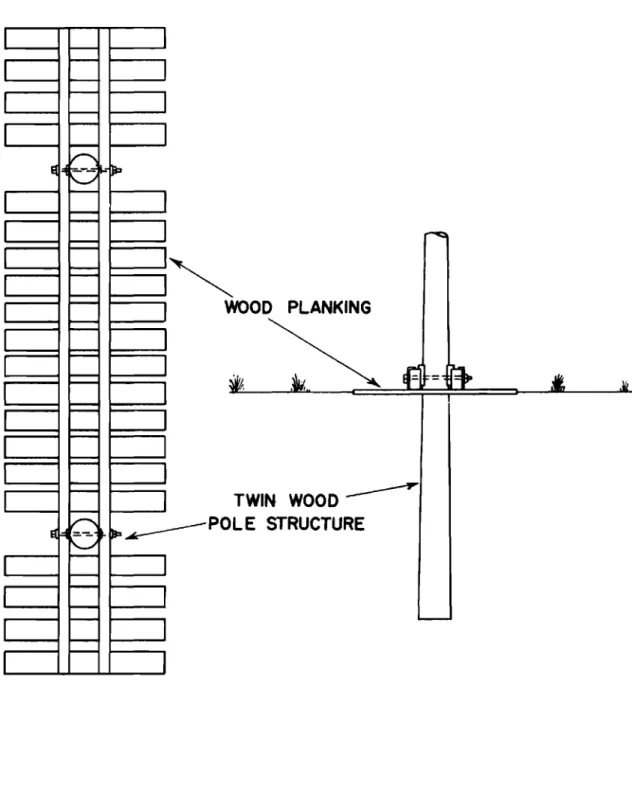
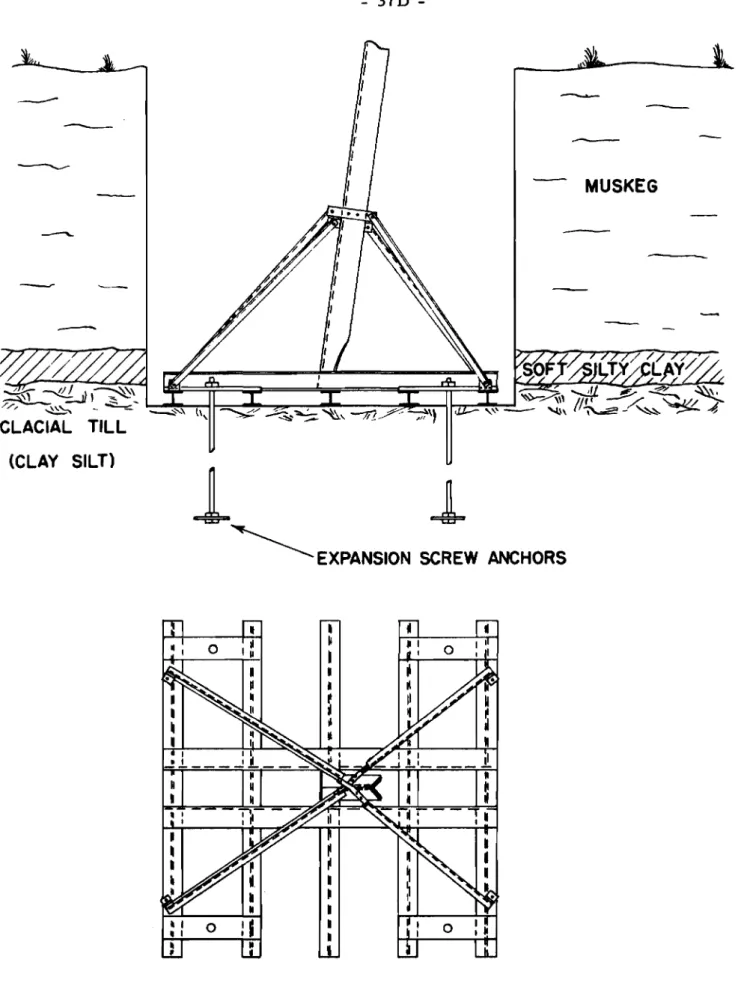
Brawner. I. 4. "Transmission Line Structure Foundations in WeakSoils" - M. Markowsky and N. J. McMurtrie. I. 5. "Evaluation of Road Performance over Muskeg in
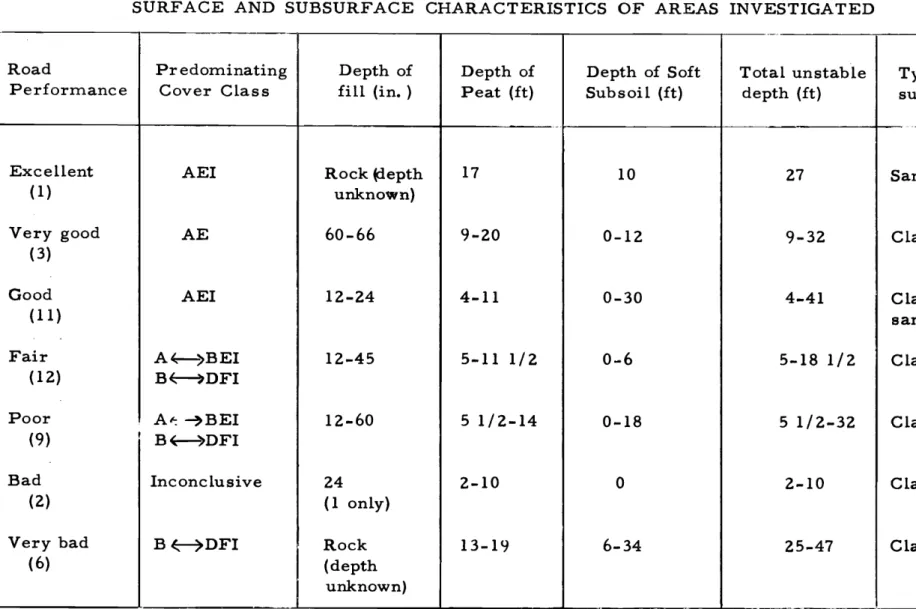
Northern Ontario - Second Stage" - I. C. MacFarlane.
Session
II,
Classification and ExplorationII. 1. Panel Discussion on Classification of Muskeg -(a) Dr. N. W. Radforth.
(b) D. G. Stoneman. (c) W. C. Bridcut.
II. 2. "Operating in Permafrost and Muskeg in the Eagle Plains Area in the Yukon Territory" - W. G. Campbell. II. 3. "Guides for the Interpretation of Muskeg and Permafrost
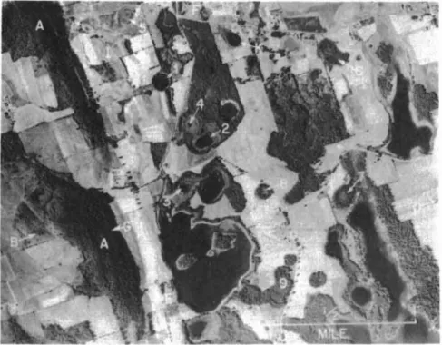
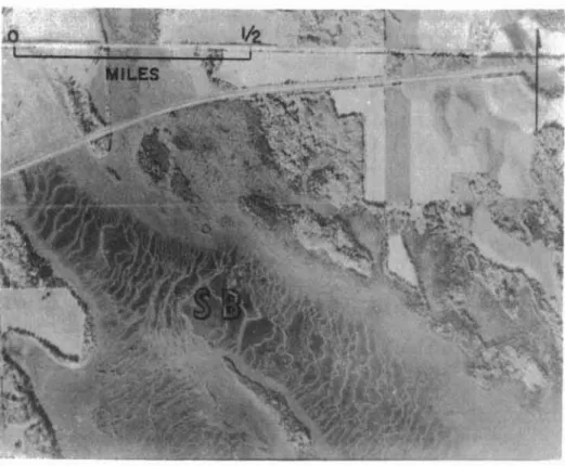
Conditions from. Aerial Photographs - Dr. J. D. Mollard. II. 4. "The Procurement of Physical and Mechanical Data
(iii)
Thur sday, April 21
Session III: Miscellaneous Invited Papers
-III. 1. "The Successful Use of Tracked Transporters in Shell' s Sear ch for Oil in the Muskeg of Northern Canada" - D. G. Stoneman,
III. 2. "Timing, Logistics and Personnel in North Country Operation" - _B. W. Gillespie.
Session IV: Permafrost
IV. 1. "Some Aspects of the Permafrost Problem" -T. C. Mathews.
IV. 2. "The Engineering Aspects of Permafrost in the Petroleum Industry" - R. A. Hemstock.
IV. 3. "Some Aspects of Muskeg in Permafrost Studies" -R. F. Legget and
J.
A. Pihlainen.IV. 4. "Climate, Archaeology and Permafrost" - T. A. Harwood. Session V: Northern Development
-Panel Discussion on "Muskeg in Relation to Northern Development" -(a)
J.
E. Savage. (b) Dr.J.
Terasmae. (c)W.B.
Dingle. (d) Dr. N. W. Radforth. (e) Dr. R. M. Hardy. Closing Re.marks.Appendix "A" - List of those present
at
Sixth Muskeg Research Conference.INTRODUCTORY REMARKS
Dr. Radforth, on b eha lf of the A ssociate Committee on Soil and Snow Mechanics, welcomed those in attendance. He read a telegram from Mr. R. F. Legget, Chairman of the Associate Committee, who expres sed his regrets at not being able to be present. Appreciation was expressed by Dr. Radforth for the assistance of Imperial Oil Limited and the Shell Oil Company in the arranging of the Conference, and specifically for the co-operation of Mr. R. A. Hemstock of Imperial Oil. Announcements were made pertinent to luncheon arrangements, chairmen of the sessions, and availability of N. R. C. muskeg literature.
1. 1 CONSTRUCTION EXPERIENCES IN PEAT BOGS AND MUSKEG IN BRITISH COLUMBIA
R. C. Thurber
In the pre-war years, SWaInpS and peat bogs were avoided
by engineers and by most agriculturists. The post-war expansion has
necessitated a new look at the vast expanses of now valuable terrain in
British Columbia. The general practice of highway engineers before the
war was to avoid swamps of any size because, after placing thousands of yards
of material, usually they still did not have a stable road. Since the war,
however, techniques of construction such as excavating, blasting, displacement, sand drains and preloading techniques have overcome many of the problems of
construction over SWaInpS and soft ground. The problem now resolves itself
into a programme of careful engineering design, with the cost depending upon
the degree of perfection required. ,For success, a high degree of engineering
skill and experience in soil mechanics are essential. Many roads and freeways
and other structures are now being built with satisfactory results over unstable
areas. There are probably more failures, however, than most people would
care to admit. Failures are projects where not only is the structure
unsatis-factory but where excessive maintenance is required and where distortion appreciably lowers the operating efficiency of the structure.
A. Okanagan Lake Darn Outlet Channel
This project involved the construction of a channel located in a swamp area adjacent to the City of Penticton and between Okanagan Lake and
Skaha Lake. Soundings indicated more than 70 feet of peat and soft marine
silts and organic clays underlying this area. A dam was constructed on piles,
although with some difficulty. The channel connecting the darn to the lakes
was begun. Excavation was completed from Skaha Lake to a point 300 feet
below the darn. The channel was left full of water as work progressed and
only minor failures and sloughing occurred. The type of material encountered
can be described as "GK3" according to the Alberta Research Council classi-fication of muskeg.
Three hundred feet of the downstream channel was to be
excavated in the dry in order to place a gravel and rock channel lining. When
the channel was almost down to grade, the large spoil banks (placed by the
drag-line) suddenly started to drop and the channel bottom came up. To prevent
this, the spoil banks were placed further back with a drag-line and a further
2
-was to drive sheet piling the full length of both sides of the channel in order to hold the excavation.
A check of borings showed that a stable c lay was encountered
at a depth of about 75 feet. This meant that sheet piling would have to be
over 75 feet long. It was apparent that piles of 50 feet or less in length
would not result in a stable condition and that piles 80 to 90 feet long would be necessary to key into the firm material at the bottom and would have to
be supported at the top to be stable. Although not entirely impossible, this
plan would have been very expensive and would have delayed the project considerably, so alternative procedures were investigated.
Indications of cracking and an upheaval were such that it
was evident that a slip circ le type of fai lure was occurring. It was also
apparent that plastic flow was taking place at depth. To arrive at tangible
values of the forces involved, the failure was analysed utilizing the simple
slip circle type of failure. A careful check of several individual points
indicated that this assumption would produce results within an accuracy that
was required for design purposes. On this basis, it was calculated that if a
bed of 3 feet of gravel and rock were in place, as in the original design for rip rap, then the channel would have a low but satisfactory safety factor after being filled with water.
It was decided to excavate the channel an extra 2 feet and place
a properly graded filter sand which
would:-(1) Prevent the soil from pumping up into the gravel and rock.
(2) Provide a working platform upon which to spread the gravel and rock.
A construction procedure was laid down such that the channe 1
was excavated in six consecutive 50 foot sections. The sand acted satisfactorily
as a filter; as the load was placed, instead of the muck liquefying and becoming unstable, the water was able to escape through the sand and the soil increased
in strength. The job was completed without further difficulty and performance
3
-B. Project No. 459 (Maillardville-Coquitlam Highway)
The Maillardville- Coquitlam Highway, constructed during
1954 and 1955, is a project which may be considered a failure. Up to 1954,
the Department of Highways was not organized or staffed to investigate and
predict problems before they occurred. It was the policy to build the road
according to past experience and, if some unusual soils prob lem occurred,
the Materials Engineer was called in. Such was the case with Project No. 459.
Following enquiries by the contractors who were worried by the great expanses
of muskeg, a brief investigation was made. Penetration tests were carried
out with a probe consisting of a 5/8 -inch diameter steel rod, joined by thin
couplings and with a bullet- shaped nose. Two men forced the rod downward;
the depths reached by an estimated 100 lbs. and 400 lb s , pressure were recorded.
A few auger holes were advanced to correlate the soils
encountered with the penetration results. There were two main sections
to the swam.p area; from Maillardville to Cape Horn - about 6,400 feet long; and the other section from Cape Horn to Es sondale - about 7 , 500 feet long.
The depth of soft material of both sections was determined. The
classi-fication was "Bc 14" and "Cd 14". (Alberta Research Council Classiclassi-fication). Design calculations indicated that a grade of 8 feet with a load of about 28. 1 tons per lin. foot would be on the point of shear failure
and that a grade of
6
feet with a load of 19. 9 tons per lin. foot would probablybe safe from a shear failure. Consequently, a report was made stating that
a shear failure would not occur if a grade was placed of not more than
6
feetdepth. It was also suggested that if a floating road was utilized, a 1 foot
lift of sand should be placed over the swamp ahead of the grade to prevent peat from permeating the fill.
It was concluded that a fill of
6
feet, although it would settleexcessively, would not shear the swamp crust. However, the road would
not likely be satisfactory.
Funds were not available for displacing an average of 19 feet of peat over 14, 000 feet of road, so it was decided to float the road over
the swamp areas. During construction, numerous culverts were placed
throughout the swamp area, but on piles. In a particularly soft section,
4
-feared that a shear failure might occur, sand drains were placed in that area. About 3, 000 sand drains were placed in this section extending along 1, 000 feet, averaging about 30 feet deep, 18 inches in diameter, and 9 feet on centers. A closed end mandril was driven down by an air-powered pile driver. After filling with sand, air pressure was applied to force the sand out as the mandril was withdrawn.
Settlement readings were taken at the time and have been continued. After about two years a comparison indicated that the settlement was very similar in the sand drains area to that encountered elsewhere. However, there was no shear failure through that area; therefore, the sand drains were considered to have served an effective purpose.
This section of road settled considerably but the piled culverts did not. As a result, the cost of maintenance has been rather high. However, the section of road between the culverts stood up for several years fairly we II under extreme ly heavy traffic and, apart from the cu lverts which
continually punched through the pavement, the road performed satisfactorily.
c.
Pacific Great Eastern RailwayA large number of problems were encountered in connection with the construction of the Pacific Great Eastern Railway. A study of
several locations where failures had occurred, utilizing drilling, testing, and analyses, produced some interesting results and conclusions. These conclusions were successfully utilized in applying corrective and stabilizing work at the various locations.
In investigating several of these failures, it was noted that a considerable amount of peat remained under the center of the grade in spite of large quantities of inorganic soil or gravel which had been placed in an attempt to fill the area. Thus, it was possible to account for the complaint that, even after filling these swamps completely with rock or gravel, undesirable and uneven settlement and distortion of the grade later occurred.
On the basis that in new construction of a railway grade and before final ballasting and lifting of the track small settlements are not particularly undesirable, certain recommendations were
made: 5 made:
-(1) For grades satisfactory for high speed travel,
any or ganic material of depths up to 6 or 7 feet
should be excavated prior to construction.
(2) For depths of or ganic material over
6
or 7 feet,explosives should be used in the normally prescribed manner by discharging after the fill is in place.
(3) Where the grade was already built, and the track was in use, the practice of putting in granular fill in lar ge quantities to keep the track up to
grade should be discontinued. Berms should
first be built to counterbalance the grade. These berms could be built of any inexpensive material, usually clay from adjacent cuts. Once such berms are built, the grade can be
brought up to the proper elevation. This
procedure has been successfully utilized; its main advantage being that far les s material is required for equilibrium and, of course,
local inexpensive soils can be used for berms.
Several of these sections have been observed to show signs of unevennes s after several months of heavy traffic but this is not serious
on a railway. Also, it has been noted that where ditching and drainage of
the swamps had been carried out, a gradual lowering of the water table had a direct and appreciable effect on the settlement of the grade.
D. General Recommendations Regarding Construction in Muskeg
(1) No primary or secondary highway to carry heavy modern traffic should be built over any depth of
peat or or ganic matter. Such or ganic material
should be displaced or excavated.
(2) Soft silts and compressible clays often encountered under peat should be consolidated rapidly by sand drains and preloading if it is apparent from the testing programme that appreciable settlement can be expected after completion of the road.
6
-(3) Corduroy or timber grillage is not necessary under roads with a grade of more than about 3 feet.
(4) Swamps will definitely carry an embankment which can be used for a railway or a highway
providing it is possible to design for the differential settlement at the transition points and to design for any bridges or culverts required.
(5) A rule of thumb is that approximately 1 foot of settlement can be expected for every 10 feet of swamp depth for such floating grades.
********
1. 2 MUSKEG AND PERMAFROST IN HIGHWAY DEVELOPMENT IN
THE CANADIAN SUB-ARCTIC J. P. Walsh
Permafrost as Nature's Aid in Construction over Muskeg
It does not matter what physical form a highway foundation rnay have if it is strong enough and stable enough. Where the subsurface
can be maintained permanently frozen, that is sufficient highway support, whether the subsurface be select granular materials or of entirely organic composition. The engineer's problem is to preserve the permafrost in all foundation materials where thaw would cause a partial or total loss of support. From soil mechanics we know which inorganic soils are affected by frost action. We also know that organic soils have little strength unless frozen. At the Snag Airport on the Yukon-Alaska boundary, the soil is a coarse
gravel with little or no fines and no loss in subgrade support resulted from annual thaw even though the active layer was 18 feet deep. In other areas where silt exists and where conditions were once such as to permit ice segregation, the thawing of the subsoil will cause total loss of support. When thawed, such soils are more difficult to deal with in the north than
7
-further south, for two
reasons:-(1) The soil at greater depth will r ern a.i n frozen
so there is no escape for excess rn oistu r e in
that direction.
(2) There is less loss by evaporation in these latitudes.
In rnarry of the areas where the soil structure is such as to p e r rnit the
fo r m at i on of ice lenses, this has already occurred. If these soils are
allowed to thaw, support is lost due to their extremely high rn oi atu r e
contents. Moisture content rnay well be several hundred percent in
inorganic soil and two thousand percent in rnu sk eg, Physical feature
exarnp l e s of this is the silt hill and the pingo. North of Yellowknife,
in an excavation in silt, ice lenses of two feet in thickness were exposed. Consideration of pe r-rnafr o st in highway construction is
only necessary when it is within construction depth. After SOIne experience
in an area, the depth to pe r maf r oat can be eatirn at ed f r orn surface cover
and topography. Between latitudes 61 and 64 the pe r-m afr o st is to be found
at SOIne depth in a lrn o st any area, as has been proved by the rndni ng industry
in sinking shafts and also in oil drilling. The pe r.m afr o st level is higher
and the active layer shallower with increase in the density of tree growth, the presence of organic cover and the absence of free m oi stu r e in this
cover. A dry rnu sk e g has rn any t irn e s the insulating qualities of a saturated
muskeg. Where there is SOIne natural surface drainage within a rnu sk e g area,
the channel carrying the run-off or the ponds fo r m e d in the depressions usually
cause the pe r m afr o st level to drop. Sornetirn e s the heat conductivity allowed
by this water will create an under ground channel which then r erna.i ns in an
unfrozen condition. Ponds rnay have no visible drainage yet never change
surface level where they have subsurface connection to a large body of water nearby.
Utilizing the PerInafrozen Foundation in Highway Construction
The person responsible for the route location should be a
graduate of the construction force. Any possible e c onorny can be realized
only by consideration of all factor s peculiar to construction in these areas. Consider a c ornrn on situation in the Yellowknife area: a three-mile section
8
-except at the extremities. The grade at any section may be over rock or muskeg. The muskeg fill section, due to submergence and other shrinkage, will require 36,000 yards of borrow per mile plus 15,000 yards of excavation for side and offtake drainage. The embankment per mile over rock would require 17,000 yards of borrow and 5,000 yards of rock excavation (which would be used as fill). After a complete analysis, including overhaul costs, it may be found that a section from each end would be built on the muskeg and the center portion along the rock.
Some recommendations for route location
are:-(1) Every standard should be brought to a common denominator. Class
"A"
standard for grades should not be considered when alignment can only be Cl.a s s "D".(2) The first impression of a difficult area is
usually too pe s simistic. The location engineer should deal with lengthy sections governed by definite control points (such as river crossings) and should bear in mind that the shortest route may be one and one-quarter but never twice the
straight line distance.
(3) All muskeg sections whether wet or dry have to be drained. The grade will cause the muskeg on one side to become saturated eventually. Permafrost will always be at a shallower depth in dry muskeg and therefore the embankment quantities, and consequently the cost, will be
less.
(4) Rock is safe. Unit costs may be higher but design quantities for excavation through it and for borrow for embankment over it can be maintained. Also routing along rock ridges and outcrops reduces maintenance since this enables the road to blow clear of snow.
9
-(5) Total shrinkage will be high in grade construction over muskeg. Submergence, haul roads and increased embankment density relative to the borrow pit, in that order, contribute to an approximate average of sixty percent shrinkage in the Yellowknife area.
Some Recommendations for Construction
For the permanently frozen subsurface to be utilized as the highway foundation, the frost level must be maintained or raised, never lowered. Lowering of the frost level will result from any of the following:
-(a) Removal of the insulating cover.
This is usually the layer which undergoes the annual freeze-thaw cyc leo Generally this applies to an organic soil but other
soils may be the insulating medium. In the Yellowknife area, permafrost exists from two to four feet depth in si It hi Us which have little or no or ganic cover and only sparse tree growth. Due to the
topography, the active layer is well drained and no free water is available for ice
segregation in this layer. This depth of dry inorganic soil is sufficient insulating cover.
(b) Wetting the insulating cover. If necessary drainage is neglected in the slightest and the m.oisture content of the active layer is increased, then the permafrost level will drop.
(c) Disturbing the insulating cover. The ground surface in its natural state is usually
in
the best condition to hold the permafrost level10
-equipment on this surface in the summer
will have bad results. The color change
in the organic surface will cause heat absorption and any ruts or depressions will be collection ponds for water which will result in pockets of thaw.
The permafrost may be maintained at its natural level (or even raised) by the following
methods:-(a) Drainage. Constructing drainage ditches
on both sides of the center line, at sufficient distance so that the semi-circle of thaw below them will not intercept the toe of fill, and continuing these ditches to offtakes , will improve the insulating quality of the
cover. From two to two and one-half miles
of ditch may be required per mile of road. If at all possible, drainage should be carried out well in advance of construction, preferab ly a year ahead.
(b) Use the forest cover which must be cleared for right-of-way as additional insulating cover. All trees and brush should be hand cleared and laid in a mat over which the grade will be built. This will actually raise the permafrost profile under the grade after a few seasons.
(c) As a rule, never excavate on the road line. Unless it is rock, or gravel without fines,
go over it. The frost will be encountered so
quickly that the quantity reduction by cut in
the road width will be negligible and the exposing of the permanently frozen subsoi 1 may cause considerable difficulty.
(d) Set culvert s high so that heavy run- off will be carried and at other times the culvert will
11
-area of pondage above the culvert, evaporation will substitute for a flow through the culvert for seasons other than break-up and after heavy rains. A continuous flow in a culvert will cause
a basin of thaw below it. Another reason
for setting culverts high is that glaciation will occur where there is winter flow and when it is required at the break-up; the culvert will not have a capacity above the limit of icing.
(e) Where glaciation is a problem, it usually
occurs where the highway is built along a hillside for an appreciable distance. Water is trapped between the permafrost and the
active layer and a head is built up. The
road ditch will freeze to greater depth and lock on to the permafrost before this occurs
in undisturbed ground. Under sufficient
head, the water will break the surface in
or just outside the ditch. A second ditch
parallel to the road and at some distance up the s lope from it should be excavated and the ice will pile up there safely away from the grade.
Suggested Approach to Highway Development in the Canadian North
It appears that both owners and contractors are too m.uch
influenced and guided by conventional methods in highway construction. Methods which are tried and proven for southern areas are not always
correct when applied further north. Owners let, and contractors acquire,
highway jobs in which completion dates, expected performance and estim.ated
costs are quite unrealistic. The construction season at Yellowknife is from
July 1 st to October 31 st , whereas it may be twice as long and twice as good
in the Calgary area. Of the total job cost, the proportion to place men,
camp, fuel and equipment on site and to supply throughout the project is much higher at a distance of one thousand miles from the nearest city (Edmonton)
12
-than for a similar highway job in more settled districts. In addition,
there is less knowledge of proper methods in highway construction in the Canadian North than in almost any part of the world.
Some
Suggestions:-(1) Contracts should be large enough to reduce the move in - move out proportion of total cost as
much as possible. Heavy equipment should not be
sent in annually, which is the case with one-year contracts, unles s this year's contractor happens to be the successful bidder on the next job.
(2) Job specifications should be written and interpreted
in an applicable manner. There is no history of
road construction in the North and therefore there can be no fixed specifications, since these can only
be written when based on past tried and proven methods.
It is not unusual to find a young conscientious
engineer attempting to apply standard specifications which are applicable to road construction in southern
Canada. Also a contractor may enter a job with an
equipment choice based too greatly on contract specifications and too little on fie ld study. (3) At this time and until many more highways are
bui lt and know ledge gained, both owner sand contractors should adopt a non-rigid approach. Should one contractor become educated, he must
still compete on subsequent jobs with those who still bid unrealistically due to ignorance of the problems peculiar to this area.
Since method is still to be learned, they might be learned on the job but not at the expense of it. When those factors are encountered for which correct specifications are yet to be written, then field decision based on the collective knowledge
13
-of all associated with the project should prevail. (4) Staff should be chosen on a basis of more
remuneration for a more demanding job. The employer should seek out experienced men and compensate financially for this experience as well as for isolation. Highway construction in Northern Canada should not provide just an interim position for young graduates out of engineering school or for an in-training superintendent or fo r ern a.n; but the challenge is so great that experienced men properly compensated should be responsible for this work.
***.:c****
I.3 THE PRACTICAL APPLICATION OF PRECONSOLIDATION IN HIGHWAY CONSTRUCTION OVER MUSKEG
C. O. Brawner
Peat or muskeg is of limited geologic extent in British Columbia. However, in the Lower Fraser Valley area, muskeg deposits are quite numerous. About 1955, when it became apparent that several new major highways were necessary in the vicinity of Vancouver, alignment requirements and right-of-way costs indicated it would be desirable to locate portions of these highways through muskeg areas.
These deposits range in depth from about 6 to 30 feet. It was obvious that the most widely accepted construction procedures, removal or displacement of the peat, would be very expensive. Hence, the B. C. Department of Highways gave consideration to other methods that might offer greater economy and still provide high performance and
14
-Of the methods considered, preconsolidation, often used to stabilize soft inorganic soil, appeared to offer many advantages, particularly economical construction. If the procedure was successful, it was estimated that savings in excess of $50,000 per lane-mile could
be saved compared to the removal or displacement techniques. Considering this possible saving, the Department approved detailed studies, comprising
laboratory and full- scale field investigations. Two of these studies have been completed (1) (2) (3) and a third is still underway. Based on the results of these studies preconsolidation has been or is being used on three major highway projects.
It is the purpose of this paper to summarize the findings of these studies, outline experience on several highway projects and to present design and construction procedures that have been developed. It is important to note that the investigations were directed more toward practical rather than pure research.
Principle of Preconsolidation
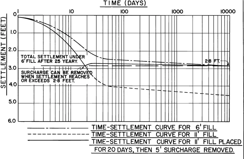
The principle of preconsolidation is relatively simple. A
load in excess of that which will finally be carried by the soft ground is placed and allowed to settle until the ultimate settlement that would occur under the final load has been reached. The excess load is then removed and road construction completed. The principle is illustrated in Figure 1. Curve 1 is a typical time- settlement curve for a
6
foot fill placed over a peat deposit. The settlement, with no surcharge, reaches2.
8 ft. in 25 years. This 2.8 feet of settlement can be obtained during the construction period by placing an 11 foot fill for about 20 days (Curve 3). Aft.er this period the excess 5 feet is removed and future settlement will be negligible.Practical Problems Associated with Preconsolidation
While the principle of preconsolidation is relatively simple, there are several major problems that must be overcome in order for the procedure to be
successful:-(a) Construction must be carried out in such a manner that over loading of the peat and subsequent failure does not occur.
15
-(b) Excessive settlements, generally very non-uniform, must be reduced to within to lerab le tim its.
(c) Deflection and rebound under heavy traffic loads resulting in high compression,
tension and bending stresses in the asphaltic concrete must be maintained within tolerable limits to prevent failure.
Brief Ou t Ii ne of Research
Three full-scale field test sections were constructed.
General location details are shown in Table 1.
r
Depth of Material under Length ofLocation Peat Peat Deposit
Lulu Island Up to 11 feet Silt and sand, Approx. 2
(Vancouver- U. S. ) clay below 70 ft. miles
Mai llardville Up to 18 feet Medium soft clay, Appr ox. 1
(Trans - Canada silt and ti II mile
Highway)
Sper ling Avenue Up to 15 feet Very soft clay Approx. 1
(Trans - Canada mile
Highway)
!
j
'.
Table I - General Details of Test Section Locations
The first test section at Lulu Island was constructed to dete rrr.Lne whether preconsotidation could be utilized for highway
construction over peat. The peat at the Maillardville site was somewhat
16
-At Sperling Avenue, clay, with a lower shear strength than the overlying
pe at , extended to depths up to 60 feet and created a problem of suffi cie nt
rnagnitude to warrant a third test section.
Prior to the construction of the test sections, fie ld soil
surveys were carried out and vane shear tests performed. Samples ..
di s tu r b e d and undisturbed, obtained during the soil survey, were subjected
to nurn e r ou s laboratory tests. Field instrumentation comprising piezometers,
settlement gauges and lateral movement gauges were installed before the
test fills were placed. Reading of the instrumentation was carried out while
the surcharge was in place and for some time after removal. In addition,
plate bearing tests were run on the preconsolidated peat. Results of the
first two test sections have been published elsewhere (1) (3).
The Sper ling Avenue location is the most c r it i cal, with the
underlying soft clay posing a greater problem than the peat. Stability
analysis revealed only 3 feet of granular :material could be placed without a shear failure and settlement computations indicated 9 feet of settlement,
to occur over at least 50 years, can be expected. At the test section, six
to eight feet of sawdust, which will settle below the water table, was placed
on the peat before the gravel to maintain the grade above ground line. In
addition, vertical sand drains are being installed to determine if they will
rriat e ria l ly increase the rate of consolidation. Results of this latter study
will not be co:rnplete for at least another six months.
Brief Discussion of Test Results
DetaiLel information regarding test results has been
published previously (1)(3). A brief discussion of the most sigrrif'i c arit
results fo l low s
r-(a"; Strength Characteristics and Ernbankment Stability
Strength determinations for peat require some special
attention, Unr-o nfi ne d c ornp r e s sion tests are unsuitable because of
jrainageiuring the test. Undrained triaxial tests have been carried out;
howeverc. san'1p le preparation is very difficult. Field vane shear tests
are rn o r e readily performed, providing the peat is es sentially fine g r ai.ned , While there is some discussion as to the validity of the vane test in peat
17
-embankment designs based on these results have not resulted in unstable conditions.
With the validity of strength tests for peat not well established, detailed theoretical stability analyses are not as yet considered justified. Accordingly, the strength is assumed to be
cohesive in nature and the critical height of embankment is determined from the approximate formula
h c = 6c
-0
where h c
=
critical height (feet)c
=
cohesion=
shear strength (p. s ,f. )0' =
unit weight of fill (p. c.f. )On actual construction, the installation of fair ly simple instrumentation can be used to forewarn of impending instability. If pore water pressure in the peat exceeds about
500/0
of the effective pressures or if lateral movement exceeds about 3 inches, stability is considered critical.Fortunately, the permeability of peat is generally quite high, and thus increased pressure results in a fairly rapid increase in strength. If the peat does not contain fine grained inorganic soil or if the loading is not extremely rapid, embankment stability for fills up to about 8 feet in height is not usually a problem, except where very soft c lays under lie the peat.
(b) Settlement and Consolidation Characteristics
As for shear strength determination, evaluation of the rate and magnitude of settlement due to the weight of a fill is difficult. The main problem arises from the difficulty in obtaining and preparing representative samples. The Swedish foil sampler has been fairly
successful in obtaining reasonably undisturbed samples. Large diameter thin wall tubes have also been used with fair success. Where sample preparation is difficult, the samples have been quick frozen and trimmed
18
-in the frozen state, placed -in the consolidometer and allowed to thaw for 24 hours before testing.
Another problem concerns the selection of a suitable
consolidation theory. The Terzaghi theory of consolidation (4) applies
to p r i m a ry consolidation where the coefficient of consolidation is as sumed
constant. This coefficient varies markedly for peat, hence the theory
does not apply. At the same time, however, it is considered that peat
consolidation is largely primary, rather than secondary, as is often suggested.
In order to evaluate the rate and magnitude of settlement
it is as sumed that Darcy's Law is valid. Consequently, the magnitude
of the settlement is considered to vary as the thicknes s of the peat layer and the rate of settlement to vary as the square of the thickness.
Reasonable agreement using these relationships was obtained between
the laboratory and fieId results during the studies.
A procedure to estimate the magnitude of settlement
has been prepared by Lea (3), Figure (2). Curve ABC is the calculated
fieLd load- settlement curve on which each point gives the settlement which
would occur 25 years after a given load is applied. Curve DEF is a
si rt.i la r calculated field load- settlement curve for the allowable construction period - in this case, three months.
Curves AB C and DEF are constructed by running special
consolidation tests at different pressures. Such tests are loaded at the
fieLt rate (correlated by the square law) and the load is left on for a time
corresponding to 25 years. A family of curves is obtained and the 3 month
and 25 year curves are plotted.
Point D indicates that if a 0.30 ton load is placed it will
settle 2, 5 feet in three rn orrth s , Curve GDB represents the load which
rr.u st be ad.Ie d to maintain the required finished roadway. The slope and
shape of this curve are affected by the location of the water table and unit
weight of the fill materials. Point B represents the ultimate condition which
must be achieved and the horizontal projection of B to line DEF, point E, gives the load required to obtain the 25 year settlement in three months.
19
-(c) Flexible Pavement Design
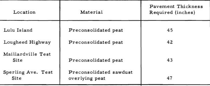
Of the pavement design methods available there appear to be only four procedures which may lend themselves to the determination of pavement thickness over preconsolidated peat.
(1) Plate Bearing Test - This test, developed by Dr. Norman McLeod for the Canadian Department of Transport, has been used very successfully in airport pavement design (5) and modified for highway
design. Tests on the surface of the preconsolidated
peat at various Locations reveal about 40 to 48 inches of pavement (asphaltic concrete and base) are required.
The results of the tests are shown in Table 2. It should
be noted that the thickness of pavement determined by the plate bearing test is affected by the strength of the
granular base. In the present tests "K", the base
course constant varied from 50 to 65. If, however,
the base is poorly compacted, "K" may be greater and increase pavement requirements.
Pavement Thicknes s
Location Material Required (inches)
Lulu Island Preconsolidated peat 45
Lougheed Highway Preconsolidated peat 42
Mai l l a.r dvi l le Test
Site Preconsolidated peat 43
Sperling Ave. Test Preconsolidated sawdust
Site over lying peat 47
Table 2 - Pavement Requirements for Preconsolidated Peat as determined by the Plate Bearing Test.
20
-(2) BenkelITlan Beam Test - Recent testing at the W. A. S. H. O. test
road (6)セ in California (7
L
British Columbia and elsewhere hasindicated pavement will not fail under repeated heavy traffic load
applications provided deflection, as measured by the Benkelman Beam, .Io e s not exceed about 0.030 inches at temperatures near freezing
and about 0.045 inches during the surnrn e r , A series of tests using
the procedure developed at the W. A. S. H. O. road test were carried
out to relate pavem.ent pe rfo r m anc e and deflection to pavement thickness.
The results are shown in Figure 3. Pavement thickness of about 40 inches
is iniicated.
(3) Shear Strength Method - This method has been used most frequently
in England (8). Based on vane shear tests at Lulu Island a depth of
pavement of 22 inches was indicated. This thickness is obviously too
low considering pavement performance. The discrepancy may be due
to the vane shear test not being reliable in peat, that peat has a moderate angle of shearing resistance, or that radius of curvature and not shear st r e ngt h is the limiting design factor.
(4) Elastic Theory Method - Laboratory and full-scale tests in Sweden
(9) (10) and B. C. (3), suggest that the elastic theory method, which
results in a radius of curvature criterion, is also a satisfactory pavement
design procedure for roads over peat. Using the method outlined in Reference
9, 48 inches of pavement is required.
The fine fibrous and granular peats in the lower mainland
of B. C. have reasonably similar properties. Consequently, a pavem.ent
thickness of 40-48 inches is considered valid for preconsoLidated peat in
this area.
Use of PreconsoLidation in B. C.
Based on the present studies, it was considered that
preconsoliJation can be utilized to provide economical and stable highway
c.on st r u cti ori. Consequently the B. C. Highway Department has used or is
using preconsolidation on several m.ajor projects. Results of experience on
21
-(a) Lougheed Highway near Boundary Road
In 1957 it was considered necessary to widen the Lougheed
Highway to four lanes. About 1,200 feet of the highway crossed a peat
deposit ranging in depth up to 14 feet. The old highway was floated over
the peat and was badly deformed. Excavation and replacement and vertical
sand drains were initially considered but discarded in favour of preconsoli-dation.
The entire fill was brought to grade and a five foot surcharge
placed and left for three months before removal. Immediately after removal
the base gravel and asphaltic concrete were placed. No major construction
difficulties were encountered.
This highway has now been in service for nearly two years ani no noticeable differential settlement or pavement failure has occurred.
(b) Chilliwack By-Pass
About 2, 000 feet of the Trans-Canada Highway near
Chilliwack crosses muskeg ranging up to 35 feet in depth. A grade about
8 feet above ground line was utilized. Eight feet of fill was placed initially
at which point lateral movements became excessive. Construction ceased
for three months after which another 7 feet was placed. The surcharge
was recently removed and paving will commence shortly. Again no major
problems were encountered. (c) Hart Highway
A portion of the present gravel highway, which is to be
paved this year, crosses several large muskeg areas. Four to five feet
of surcharge was placed on the grade last Fall and left over the winter. This surchar ge will be removed and the highway paved in June or July of this year.
(d) Trans-Canada Highway near Maillardville
Preconsolidation is being used to construct over a mile
of four lane divided highway near Maillardville. Generally the final grade
22
-crossing where the approach fills will reach 25 feet. No difficulty is being experienced with the shallow grade. However, the higher approach fills are presenting problems.
Considering settlement and surcharge a total depth of fiU of about 35 feet is required. With the peat only capable of supporting about 8 feet of fill initially, stage construction is neces sary. The fir st stage was constructed without difficulty. The second stage has had to be placed much more slowly as the rate of consolidation and reduction in pore
pressures have decreased considerably from that during the first stage. One possible explanation is a marked decrease in permeability of the peat. If the rate of consolidation continues to decrease as markedly for the thirJ and fourth stage, as much as two years may be required to place the total filL. This is obvious ly too long and a change in procedure such as the use of vertical sand drains, counterbalancing berms or well points may be required.
This experience suggests that preconsolidation may only be practical where the grade is up to about
6
to 8 feet above ground line. The Practical Application of PreconsolidationBased on the study sections, procedures were developed for the practical application of preconsolidation. In the light of experience gained on several highway projects, the initial procedures have in some cases been slightly modified. The general details of the requirement for successful application of preconsolidation are outlined in the following text. They are considered applicable where the underlying soil is stronger than the peat. Studies are presently continuing to develop procedures when the underlying strata is very soft highly compressible clay.
(a) Preliminary Studies
Preliminary studies should always include a subsurface investigation. The first step involves determination of the depth of the muskeg and contour of the firm bottom to indicate the most desirable
location. This is done rapidly by forcing a 5/8" diameter sounding rod by hand through the peat to firm bottom. Notes are made to include the pressure required to force the rod into the ground at various depths. By drilling the occasional test hole at sounding points the sounding rod
23
-pressure is correlated with the general soil type and the correlation
extended for all sounding points. This procedure is sufficiently
accurate to provide data to select the final alignment.
On the final location, soundings are recommended every 25 to 50 feet along the center line with offset soundings every 50 to 100
feet. Test holes shoulJ be drilled every 100 to 300 feet along the center
line to obtain samples for identification and determination of physical
and mechanical properties. If settlement computations are to be made,
undisturbed samples are required for consolidation tests.
In order to estimate the height of fill that can be placed initially, field vane shear tests at everyone foot increment of depth are recommended at locations spaced 300-500 feet along the center
line. The information and samples obtained from this field testing are
then submitted to the laboratory and design office. (b) Design
The first step in the design is to establish the desired grade and to designate the approximate location of any necessary culverts
or structures. Based on experience gained at Maillardville it is advisable
to establish the grade between 2 to
6
feet above the surface of the muskeg.Test results indicate that a minimum pavement thicknes s of 3 1/2 to 4 feet is neces sary for adequate pavement performance. Based on consolidation tests or other procedures, the amount of
settle-rr.ent an.I surcharge is estimated and quantities determined. A minimum
surcharge of 4 feet is recommended. A depth of about 7 1/2 feet of
rr.ate r i a l , which includes the surcharge, will be the approximate minimum
requirement. If granular material is not economically available, the
surcharge need not be gravel.
The s ett l err.ent of the total depth of fi 11 can be estimated
from:-(i) Consolidation test results (as outlined).
(ii) Moisture content-void ratio-coefficient of
compressibility relationships. (1) or if no testing is carried out
24
-(iii) Assume settlement will approximate 1/3 to 1/2 of the depth of fill placed, with the settlement not to exceed about 1/2 of the original thickness of the peat.
Where extensive use of preconsolidation is proposed it is r e c orr.rn e n.l e d that the first procedure be used since more accurate
estimates of s ett Ierr.ent and quantities involved will result. Where the
highway must cross the muskeg for only a short distance or where a secondary road is involved, the second or third procedure will normally be adequate.
To determine quantities, the base width of the fill is increased 3 feet for every foot of estimated settlement, if 1 1/2 to 1
side slopes are used, or 4 feet for every foot of settlement for 2:1 slopes,
All material between the base of the fill and to within
6"
to 12" of grade elevation (depending on the Highways Depa r trn ent ' scrushed gravel r equ'i r ern e nt s ) will be left in place. After the required
consoliiation has occurred, the surcharge is r ern ov ed to grade plus a
depth equal to the crushed gravel requirement. This material, if
suitable, can be designated for use in the nearest fill. For purposes
of the cost estimate, excavation, hauling and placing of the entire
quantity must be considered plus an additional allowance for excavating and hauling the surcharge.
The maximum height of fill that can be placed initially
without shear failure can be estimated from
bc/o
if fie ld vane testshave been carried out. Alternatively a s lope stability type of analysis
can be used, Experience in B. C. to date is that no fill less than 8
feet in depth has caused a failure, provided very soft clay does not under lie the peat.
Where extensive use of preconsolidation may be
employed, rn o r e accurate analysis methods may be used that consider the gain in shear strength of the peat as the fill is placed as well as the effects of pore water pressures.
25
-Provision for drainage ditches should be made if
they are required. These ditches, however, should not be too close
to the toe of the f'i l l to ensure the surface mat is not broken. Where
culverts are necessary, the estimate should be based on placing the culvert, digging it out after consolidation, placing a granular base to estab lish the required grade, then replacing the culvert and back-filling.
A further cost should be inc luded for field instrumentation
required to control construction and evaluate settlement. This estimate
can be computed based on the procedure outlined under construction. Costs for base gravel and asphaltic concrete can be treated similar ly to that for normal construction.
(c) Construction
During the clearing operation, all small brush should
be cut and left on top of the peat. Heavy timber should be tr irnrn ed at
ground level and removed from the fill area. Brush or timber should
not be burned on the muskeg as it may smolder and burn for many months
or even years. Grubbing is not required.
The next requirement is to layout the center line and slope
stakes. This is followed by the installation of the field instrumentation.
This instrumentation should include settlement plates and pi e z om et e r s
placed every 100 to 400 feet on the center line. Porous stone piezometers
may be preferred by some engineers due to their greater sensitivity. The
settle:ment plates should be placed on a levelling course of sand. The
elevation of the top of the gauge and water level in the piezometer is then
determined and recorded about 24 hours after installation. Lateral move=
ment gauges are recommended every 25 to 100 feet placed about 20 feet f'r orn the proposed toe.
Difficulty has been experienced in B. C. with field
instrumentation being damaged or broken by construction equipment. These
instruments are difficult and expensive to replace and it is suggested that the contract include s orn e provision to the effect that if field instruments are damaged or broken by the contractor he shall be responsible for r ep lac e-rn ent at his expense.
26
-After the field instrumentation has been installed and initial readings obtained, the contractor can commence placing the fill. Care should be taken to ensure the surface mat is not broken. Any culverts that are required should be placed at this time and can
be placed directly on the muskeg. Initially 2 to 3 feet of fill will be required in one lift to act as a working mattress to support the equipment. This
lift should be compacted with several passes of a wobbly wheel, rubber-tired or grid roller. The mattress should be placed over the entire length of construction before any additional fill is placed. The instrument readings should be taken
12
to 24_ hours after placing the mattress and after each subsequent lift is placed. The additional lifts should not exceed 1 foot and should be carried over the entire length of the construction before each additional lift is placed to facilitate consolidation and gain in shear strength.Placing of the fill can be continued until the required
depth including surcharge is placed, unless that depth exceeds the maximum height allowed initially. In this case the contractor should not be allowed to place additional material unless the pore pressures are less than about
SO% of the total effective pressure and lateral movements are less than
o.
25 feet.Construction should not be allowed to recommence until pore pressures reduce substantially, lateral movement ceases or the field time settlement curves indicate primary consolidation is 1000/0 -2ornplete. This degree of consolidation has occurred after 25 to 35 days on projects in B. C. and on the two test sections. To facilitate later removal" the material placed as the surcharge should not be compacted.
After the grade has been completed to full surcharge !-i-eightセ field settlement readings are continued to determine when the desired settlement has taken place. The surcharge is then removed and
if suitable can be used elsewhere. The culverts can now be dug out and replaced at the required grade. Base gravel which should be well cornpa ct e d can be placed immediately followed by final paving.
27
-Summary
1. The B. C. Department of Highways has carried out several full-scale studies in the use of preconsolidation for highway construction over muskeg.
2. Results of the studies have revealed that preconsolidation
can be successfully employed and is generally less expensive than displacement or excavation for depths of peat greater
than 5 to 6 feet.
3. The problem.s of foundation stability and differential
settlem.ent can be accommodated by the use of simple fie ld instrumentation and proper construction procedures.
4. Pavement stability can be provided on preconsolidated
peat by the use of 3 1/2 to 4 feet of granular material and asphaltic concrete.
5. Construction over peat using preconsolidation has been or
is being utilized successfully on several projects in B. C.
6.
Based on the studies and construction experience, highwaydesign and construction procedures have been developed and are outlined.
7. While the investigations have been carried out only in
the Vancouver area, it appears quite possible that
preconsolidation can be adapted for highway construction over muskeg in other areas.
28
-REFERENCES
1. Br awne r , C. O. "The Principle of Preconsolidation in Highway Construction over Muskeg", Proceedings, Fifth Muskeg Research Conference, Winnipeg, March I 959.
2. Foundation of Canada Engineering Corporation Limited, Internal Report, "Report on Maillardville Test Section", August 1959. 3. Lea, N. Do and Brawner, C.0., "Foundation and Pavement Design
for Highways on Peat", Proceedings, 40th Convention, Canadian Good Roads As sociation, Vancouver, September 1959.
40 Terzaghi, K. "Theoretical Soil Mechanics", 1943.
50 Mc Le od , No W. "A Canadian Investigation of Road Testing Applied to Pavement Design", American Society for Testing Materials, Special Publication No. 79, 1948.
6. The WASHO Road Test, Part 2, Highway Research Board, Special Report No. 22, 1955.
7. Hveem, F. N. "Pavement Deflections and Fatigue Failures", Highway Research Board, Bulletin 114, Washington, D. C., 1955.
8. Gl o s s op ,
R.
and Golder, H.Q., "Construction of Pavements on Clay Foundation Soil", Institution of Civil Engineers Road Research, No. 15, London, 1944.90 Od ern a.r k , No, "Undersokningav Elasticitetsegenskaperna hos Olika Jordarter Samt Teori for Berakning av Belaggningar Enligt
Elasticitetsteorin", Statens Vaginstitut, Medelande, 77, 1949. 10. "Om Vag ens Konstruktion Vid Hog Hjultryck", Statens Vaginstitut,
N 00
:>
10000
1000
TI ME (DAYS)
100
10
o
QイMMMMMイMセMMMイMMQMMMLMMイMセMセ⦅⦅イ⦅⦅BtBBBBBBtBBBGtBBGtBBtBGQBGtBGBM⦅⦅⦅イ⦅セ⦅⦅⦅イ⦅⦅セセ[⦅⦅⦅⦅⦅⦅⦅⦅⦅NM
..._T"""T"'TT"1t="
セセ
w
セセ
..
lJJ
10
セ
GBMセ
IJ..
.
Gセ
LLセ
;:
r-r-"
セ
" "
セ2.0
セ セW TOTAL SETTLEMENT
uセr
I"t'_セ
VGallafセr
25
yeaセセ⦅セセセセセセMセMセセセセセセセセセセセセセ
...J
3.0
セZ I I !I I,L:.
セZ,
/ J....,.('L
I-
SURCHARGE CANaE
removセ
I-
WHEN SETTLEMENT REACHES "W
OR EXCEEDS 2·8 FEET:'-en
4.0
"
- 1 _ _1 _-
-- --
- "-
...
-
--- Mセ - - Mセ
1'-1-1-5.0
jMMMMMMMiMMエMMMMMMKMMMhiMKKMhMMMKMMMKMKMKMMKKKKKMMMMKMMMエMMMKMKMKMセイ⦅⦅⦅⦅⦅⦅⦅⦅⦅⦅エMイ⦅⦅⦅⦅⦅エ⦅⦅⦅⦅⦅⦅イ⦅⦅エ⦅⦅イ⦅エtQ
- - TIME-SETTLEMENT CURVE FOR 6' FILL
- - - TIME-SETTLEMENT CURVE FOR
III
FILL
- - - TIME-SETTLEMENT CURVE FOR
III
FILL PLACED
FOR 20 DAYS, THEN 5
ISURCHARGE
remoセedN
FIG. I.-TIME SETTLEMENT CURVES ILLUSTRATING PRECONSOLIDATION
PRINCIPLE.
0·01
0·1
LOAD.
[TONs/sa. FT.]
0·2
(}3
oセQ5(}6
0·8 1·0
10
1
,...,
セw
2
W LL3
z
セ4
5
6
I--セ
7
セ W ...J8
l -I--セァ
10
セ
aセ
<,
\
セ
0
r-,
iセ ...If
セセ
セ
B
r-,
セ セ
<
"'.
セ
/)/1_\
"""'"セセ
セ
セ
C
LセセNliB
'IV
f2elo
セLNNN,
セ
-
セ
Z
セ
DI:"
セッc
-
r--....
,...""\
...セ
セセBGセ
\
r-,
1"-,..,
N 00 tJjFIG.2.
GRAPHICAL
DETERMINATION OF SURCHARGE LOAD REQUIRED
100
•
••
FI GURE-3
DEPTH OF PAVEMENT ON PEAT VS. FIELD DEFLECTION
READING.
•
セ..
-
.
N ooo
o
-o
0
0
o
DEFLECTIONS UNDER
18.000
LB.
AXLE LOAD.
o
8
o
0
SURFACE--...
0
IN POOR
CONDITION
•
• •
••
••
en
z
80
•
セセセセセセセセセセ
セZ
W
セ
60
w
セ
a,
lJ..
040
\
I
',)C
セ
"
n.
x--
K 0セ
20
surfaceセsurfaceZNセIHセxゥZZェセ]]セセセMMM[ヲRMセMッNセlNZセ
•
IN GOOD
IN FAIR
CONDITION
CONDITION
-.05
0.1
0.15
0.2
FIELD DEFLECTION READING (INS.)
(TWICE BENKELMAN BEAM READING.)
=
29
=DISCUSSION C. F. Ripley
Procedures being used by the B. C. DepartInent of Highways to construct permanent roads over muskeg in the Lower Fraser Valley area, using the method of preconsolidation, have been
presented in the paper by C.
o.
.Br
awne r entitled, "The PracticalApplication of Preconsolidation in Highway Construction over Muskeg". Reports on the engineering studies and test results on which the
procedures have been based, have been presented by the author to previous Canadian Muskeg Research Conferences and in other publi-cations (I, 2, 3, 4).
The several reports indicate that permanent embankments can and have been built successfully across muskeg in the Lower Fraser Valley, using a rational method of design based on conventional soil tests, vane shear tests and consolidation tests, and supported by
full-scale field test data. These experiences contrast appreciably with
those of the writer, sometimes painful, on several projects involving construction of 'permanent fills over deep muskeg in the same area. The differences in experience are pointed out with a view to suggesting caution against hasty or over-confident reliance on either laboratory test data, field vane tests or shoz-t-ctez-m full- scale field tests on muskeg. In doing so, the writer does not wish to detract from the use and value of such test data, but merely to warn that successful application requires correct interpretation and this in turn requires careful, experienced and sound judgment.
Shear Str ength
Analyses of two recent cases of shear failures which have occurred during construction of embankments over muskeg indicate that the computed average shear stresses at failure were remarkably close to the re:molded vane shear strength, which was about 1/2 to 1/3 the
undisturbed vane shear strength. In each case, average shear stresses
were computed for the :most critical circular arc passing through the
observable toe and heel of the rupture surface. The vane used for
30
-length of 5 inches. It was rotated at a rate of 0.4 degrees per second.
Thicknesses of peat were 34 ft at Case A and 19 ft at Case B.
The embankment at Case A failed when the total fill
thickness was
6
ft only, of which 4 ft was placed in the first lift,followed by 2 ft placed five weeks after the first lift.
The ernbankment at Cas e B fai led when a total thickne s s of fill equal to 6 ft had been placed in one lift.
Consolidation Characteristics
Settlement observations extending over a period of four years indicate that the magnitude of the long-term or secondary settle-ment of muskeg in this area may be a high proportion of the total ultimate settlement which occurs during the twenty-five year period referred to
by the author. The author indicates that 750/0 of the 25 year total
settle-セrnent occurred within 25 to 30 days after fill placement. One wonders as
to the basis of determination of the magnitude of settlement during the 25 year period, and whether the author's estimate of the long-term settle.ment after the 30 day period will not be on the low side.
The following is an interesting example of the serious
proportions which the long-term settlement may assume. A site underlain
by 17 ft of muskeg was covered with 5 ft of fill. Settlement at the end of
the so-called primary period, 50 days after completion of placing fill,
was 2. 6 ft. Settlement between 50 and 1200 days has amounted to an
additional 1. 0 ft. The s lope of the time settlement curve on a semi-log
plot is only slightly less during the so-called secondary period than
during the primary period. Extrapolating the curve to 25 year s indicates
an additional future settle:ment of about 1 ft. Thus the long-term
settle-ment will amount to 75% of the primary settlement or to between 40% and
450/0 of the total settlement. Similar behaviour in which the long-ter:m settlement has been of the same or larger order has been noted on other sites.
For such conditions, the ultimate success of the ーイ・」ッョウッャゥセ
dation method appears to be questionable. It would appear to the writer
that the preconsolidation procedure recommended by the author may
31
-ultimately to secondary settlements of nearly the same order as the
primary. The success of the recommended procedure will thus depend
upon whether or not the secondary settlements will cause excessive
unevennes s of the finished roadway surface. The question arises
whether it is possible to pre-induce the secondary settlement by
preconsolidation. This would appear to depend primarily on the
shear strength of the muskeg. Within the writer's experience the
shear strength of the muskeg at several areas of the Lower Fraser Valley has been sufficiently low that it would not support preconsolidation
thicknesses greater than the three to four feet recommended by the author, and in some cases, would not permit thicknesses that great. Where such conditions prevail, effective preconsolidation would not be feasible.
REFERENCES
1. Brawner, C. O. - The Muskeg Problem in B. C. Highway Construction,
Proceedings Fourth Canadian Muskeg Research Conference, National Research Council of Canada, A. C. S. S. M. Technical Mern o r andum 54, Ottawa, 1959, pp. 45-53.
2. Brawner, C. O. - "The Principle of Preconsolidation in Highway
Construction over Muskeg". A paper presented to the Fifth
Canadian Muskeg Research Conference, March 4, 1959.
3. Brawner, C. O. - "Preconsolidation in Highway Construction Over Muskeg", Roads and Engineering Construction, September 1959. 4. Lea, N. D. and Brawner, C, O. - "Foundation and Pavement Design
for Highways on Peat". A paper presented at 40th Convention,