Publisher’s version / Version de l'éditeur:
Vous avez des questions? Nous pouvons vous aider. Pour communiquer directement avec un auteur, consultez la première page de la revue dans laquelle son article a été publié afin de trouver ses coordonnées. Si vous n’arrivez pas à les repérer, communiquez avec nous à [email protected].
Questions? Contact the NRC Publications Archive team at
[email protected]. If you wish to email the authors directly, please see the first page of the publication for their contact information.
https://publications-cnrc.canada.ca/fra/droits
L’accès à ce site Web et l’utilisation de son contenu sont assujettis aux conditions présentées dans le site
LISEZ CES CONDITIONS ATTENTIVEMENT AVANT D’UTILISER CE SITE WEB.
Internal Report (National Research Council of Canada. Division of Building
Research), 1983-10-01
READ THESE TERMS AND CONDITIONS CAREFULLY BEFORE USING THIS WEBSITE.
https://nrc-publications.canada.ca/eng/copyright
NRC Publications Archive Record / Notice des Archives des publications du CNRC : https://nrc-publications.canada.ca/eng/view/object/?id=32a768d7-e874-44ce-b23a-8feef4ce6831 https://publications-cnrc.canada.ca/fra/voir/objet/?id=32a768d7-e874-44ce-b23a-8feef4ce6831
NRC Publications Archive
Archives des publications du CNRC
For the publisher’s version, please access the DOI link below./ Pour consulter la version de l’éditeur, utilisez le lien DOI ci-dessous.
https://doi.org/10.4224/40001328
Access and use of this website and the material on it are subject to the Terms and Conditions set forth at
Fire tests on reinforced concrete columns: specimen no. 7
Ser
I
TH 1
National ResearchI
n.
484 Council CanadaConseil national de recherche Canada
FIRE TESTS ON REINFORCED CONCRETE COLUMNS, SPECIMEN NO.
7
by T.T. L i e and T.D. Lin
Private copy for:
&?
"a
DBR
Internal Report 484NATIONAL RESEARCH COUNCIL OF CANADA DIVISION OF BUILDING RESEARCH
DBR INTERNAL REPORT NO. 484
FIRE TESTS ON REINFORCED CONCRETE COLUMNS, SPECIMEN NO. 7
by T.T. Lie and T.D. Lin
Checkedby: T.Z.H. Approved by:
L.W.
Gold Date: October 1983Prepared for: Record Purposes
ABSTRACT
Results of a fire test on a reinforced concrete column are given. The test is one of a series of twelve tests carried out in the first phase of a joint study on the fire performance of concrete columns by the National Research Council Canada and the Portland Cement Association. The column was made with siliceous
aggregate. Its section size was 305 x 305 mm (12 x 12 in.). It was tested to study the influence of load on the fire resistance of the column.
FIRE TESTS ON REINFORCED CONCRETE COLUMNS SPECIMEN NO. 7
T.T. L i e and T.D. Lin*
T e s t s were c a r r i e d out on a s e r i e s of r e i n f o r c e d c o n c r e t e columns a s p a r t of a s t u d y t o develop methods f o r t h e d e t e r m i n a t i o n of t h e f i r e r e s i s t a n c e of such columns. The s t u d y was a c o o p e r a t i v e e f f o r t between
t h e N a t i o n a l Research Council Canada and t h e P o r t l a n d Cement
A s s o c i a t i o n . I n t h e f i r s t phase of t h e s t u d y 12 columns were t e s t e d . The columns were designed and manufactured by PCA i n Skokie, I l l i n o i s , and t e s t e d i n t h e NRCC l a b o r a t o r i e s i n Ottawa. The specimens, method of t e s t i n g and t e s t r e s u l t s a r e d e s c r i b e d i n s u c c e s s i v e r e p o r t s .
T h i s r e p o r t d e a l s w i t h specimen No. 7, which was t e s t e d t o s t u d y t h e i n f l u e n c e of l o a d on t h e f i r e r e s i s t a n c e of t h e column.
TEST SPECIMEN
The specimen c o n s i s t e d of a s q u a r e t i e d r e i n f o r c e d c o n c r e t e column. D e t a i l s of t h e specimen and i t s f a b r i c a t i o n a r e g i v e n below. Dimensions
S e c t i o n s i z e : 305 x 305 mm (12 x 12 i n . ) Height: 3810 mm (12 f t 6 i n . )
M a t e r i a l s
Cement: Type I , a g e n e r a l purpose cement f o r t h e c o n s t r u c t i o n of r e i n f o r c e d c o n c r e t e s t r u c t u r e s .
Aggregate: S i l i c e o u s sand and g r a v e l from Eau C l a i r e , Wisconsin. The maximum s i z e of t h e a g g r e g a t e was 19 mm (314 i n . ) . The g r a d a t i o n
curve i s shown i n Fig. 1. P e t r o g r a p h i c i n f o r m a t i o n on t h e a g g r e g a t e , o b t a i n e d a c c o r d i n g t o ASTM ~ 2 9 5 - 7 9 l , i s given i n T a b l e 1. P h y s i c a l p r o p e r t i e s of a g g r e g a t e : S p e c i f i c g r a v i t y of sand ( 2 . 6 3 ) ; s p e c i f i c g r a v i t y of g r a v e l (2.57); m o i s t u r e c o n t e n t of sand ( 4 . 0 % ) ; m o i s t u r e c o n t e n t of g r a v e l ( 1 . 0 % ) ; s a t u r a t e d s u r f a c e d r y u n i t weight of g r a v e l (1678 kg/m3) (104.9 l b / f t 3 ) ; f i n e n e s s modulus of f i n e a g g r e g a t e ( 2 . 9 6 ) ; f i n e n e s s modulus of c o a r s e a g g r e g a t e ( 1 . 7 3 ). S t e e l r e i n f o r c e m e n t : Deformed 25M (No. 8) l o n g i t u d i n a l
r e i n f o r c i n g b a r s and 10M (No. 3 ) t i e s , m e t i n g t h e r e q u i r e m e n t s of ASTM
-
*Senior r e s e a r c h e n g i n e e r , P o r t l a n d Cement A s s o c i a t i o n . Skokie, I l l i n o i s .
D e s i g n a t i o n ~ 6 1 5 - 6 0 2 . The y i e l d s t r e s s of t h e 25M b a r s was 443.7 MPa (64.3 k s i ) and t h a t of t h e 10M b a r s 426.5 MPa (61.8 k s i ) . The u l t i m a t e s t r e n g t h of t h e 25M b a r s was 730 MPa (105.8 k s i ) and of t h e 10M b a r , 671 MPa (97 k s i ) .
Concrete mix: The c o n c r e t e mix was designed t o produce a 34.5 MPa (5000 p s i ) s t r e n g t h non-air-entrained c o n c r e t e . A waterlcement r a t i o of 0.6 was used. The slump was 77 mm (3.04 i n . ) . Batch q u a n t i t i e s a r e a s f o l l o w s : cement, 307.3 kg/m3 (518 l b / y d 3 ) ; c o a r s e a g g r e g a t e ,
1054.3 kg/m3 (1777 1 b l y d 3 ) ; sand, 871.5 kg/m3 (1469 1 b l y d 3 ) ; w a t e r , 153.7 kg/m3 (259 1 b l y d 3 ) . The measured p r o p e r t i e s of t h e c o n c r e t e were: a i r c o n t e n t , 1.81%; d e n s i t y 2412 kg/m3 (150.53 l b / f t 3 ) ; compressive s t r e n g t h a t 28 days ( c a s t d a t e 1 August 1977). 35.3 MPa (5117 p s i ) .
Fabrication
C a s t i n g
The column was c a s t i n a s p e c i a l l y designed form. A t t h e s t a r t of c a s t i n g , t h e f r o n t of t h e form was l e f t open f o r d e p o s i t i n g f r e s h c o n c r e t e . The c o n c r e t e was mixed i n a 0.17 m3 ( 6 f t 3 ) t i l t i n g drum mixer. Shovels and scoops were used t o d e p o s i t c o n c r e t e i n t h e form.
A s m a l l i n t e r n a l v i b r a t o r was a p p l i e d t o c o n s o l i d a t e t h e c o n c r e t e . A s c a s t i n g p r o g r e s s e d upwards, t h e window p i e c e s were s u c c e s s i v e l y c l o s e d and t i g h t l y b o l t e d t o t h e form t o a v o i d p o s s i b l e m o i s t u r e l e a k s .
L i f t i n g hooks were embedded on o p p o s i t e s i d e s of t h e t e s t specimen a t 800 mm ( 2 f t 7 112 i n . ) from t h e t o p of t h e column. A c y l i n d r i c a l humidity w e l l 3 w i t h a d i a m e t e r of 4 m (5132 i n . ) was p o s i t i o n e d a t mid-height of t h e column f o r measuring t h e r e l a t i v e humidity a t mid- d e p t h .
R e i n f o r c i n g c a g e
The r e i n f o r c i n g cage was assembled by welding each end of 4
l o n g i t u d i n a l main r e i n f o r c i n g b a r s t o a s t e e l end p l a t e . The b a r s were c u t t o 3800 mm (12 f t 5 112 i n . ) and machined a t b o t h e n d s , f o r a
l e n g t h of 19 m (314 i n . ) t o a d i a m e t e r of 19 m. F i g u r e 2 shows d e t a i l s of t h e f i n i s h e d b a r s . The dimensions of t h e end p l a t e s were 533 x 533 x 25 m ( 2 1 x 21 x 1 i n . ) . I n each c o r n e r of t h e p l a t e , 20.6 mm (13116 i n . ) h o l e s were d r i l l e d t o accommodate t h e l o n g i t u d i n a l b a r s . The c e n t e r s of t h e h o l e s were spaced 92.1 mm ( 3 5 / 8 i n . ) from t h e c e n t r e l i n e s of t h e p l a t e s . I n t h i s way a column was o b t a i n e d w i t h a s e c t i o n of 305 x 305 m (12 x 12 i n . ) and a cover of 47.6 m ( 1 718 i n . ) t o t h e main r e i n f o r c i n g b a r s and 38.1 mm ( 1 112 i n . ) t o t h e s t i r r u p s . The main b a r s and s t i r r u p s were t i e d t o g e t h e r t o complete t h e s t e e l cage which, i n c l u d i n g t h e s t e e l p l a t e s , was 3810
nrm
Welding
The p r o v i s i o n s of AWS D e s i g n a t i o n ~ 1 2 . 1 - 7 5 & were followed when welding p l a t e s and b a r s . These members were p r e h e a t e d w i t h a propane
t o r c h t o 288'C (550°F), t o p r e v e n t b r i t t l e f a i l u r e d u r i n g welding. The s i d e f i l l e t weld was done around b a r s on t h e i n n e r f a c e of t h e bottom p l a t e . McKay E10018-D2 and DYTRON-579 welding r o d s were used. Both t y p e s of welding r o d s have t e n s i l e s t r e n g t h of 835 MPa (121 000 p s i ) . M i l d - s t e e l welding rods were used t o f i l l up t h e 6 mm (114 i n . ) deep h o l e s on t h e o u t e r f a c e s of t h e p l a t e . The rough s u r f a c e s of t h e welded j o i n t s on t h e o u t e r f a c e of t h e p l a t e were ground t o a smooth
f i n i s h .
The welding of t h e t o p s t e e l p l a t e was performed a f t e r t h e c a s t i n g of t h e columns. Refore p o s i t i o n i n g t h e t o p p l a t e , a 6 mm (114 i n . ) l a y e r of mortar was s p r e a d o v e r t h e t o p of t h e column t o e n s u r e good c o n t a c t between s t e e l and c o n c r e t e . The mortar was made of one p a r t cement and t h r e e p a r t s s i l i c e o u s sand. Using t h e same procedure a s f o r t h e bottom p l a t e , t h e t o p p l a t e was welded on t h e o u t e r s i d e t o t h e b a r s and smoothed.
C u r i n g
The c o n c r e t e was cured under damp b u r l a p f o r 7 days a t 21 t o 2 4 ° C (70 t o 75°F). The form was t h e n s t r i p p e d , and t h e column c o n d i t i o n e d i n an atmosphere c o n t r o l l e d a t 21 t o 24'C and 30 t o 40% r e l a t i v e humidity.
The column was removed from t h e k i l n p e r i o d i c a l l y t o c o o l a t 23'C (73°F) s o t h a t t h e r e l a t i v e humidity could be measured. Two hundred s e v e n t y - f i v e days a f t e r c a s t i n g , t h e r e l a t i v e humidity i n t h e c e n t e r of t h e column reached 85%, and t h e column was wrapped i n p l a s t i c t o
p r e v e n t change of i t s m o i s t u r e c o n t e n t .
Thermocouples
Butt-welded chromel-alumel thermocouples w i t h a t h i c k n e s s of 0.912 mm (0.0359 i n . ) were used t o make thermocouple frames f o r
measuring c o n c r e t e t e m p e r a t u r e s a t d i f f e r e n t l o c a t i o n s i n v a r i o u s c r o s s s e c t i o n s of t h e columns. Each frame c o n s i s t e d of a number of thermo- c o u p l e s t i e d t o s t e e l r o d s t h a t were f i r m l y s e c u r e d t o t h e main
r e i n f o r c i n g b a r s . Temperatures were measured a t t h r e e l e v e l s : a t one- q u a r t e r h e i g h t , a t mid-height and a t t h r e e - q u a r t e r h e i g h t of t h e
column. A t mid-height t h e t e m p e r a t u r e s were measured a l o n g t h e whole l e n g t h of a c e n t e r l i n e and a d i a g o n a l of t h e s e c t i o n ; a t t h e o t h e r two l e v e l s t h e t e m p e r a t u r e s were measured o n l y a l o n g h a l f of t h e c e n t e r l i n e and h a l f of t h e d i a g o n a l of t h e s e c t i o n . The l o c a t i o n of t h e
thermocouples i n t h e c o n c r e t e and t h e i r numbering a r e shown i n F i g s . 3 and 4.
I n a d d i t i o n , a number of thermocouples were mounted on t h e
r e i n f o r c i n g s t e e l b a r s and t i e s . The l o c a t i o n s of t h e thermocouples on t h e s t e e l a r e shown i n Fig. 5 and i n more d e t a i l i n Fig. 6.
A l l thermocouples were i n s t a l l e d i n such a way t h a t t h e w i r e f o l l o w e d a n i s o t h e r m f o r a t l e a s t 12.7 mm (112 i n . ) from t h e j u n c t i o n . T e s t Apparatus
The t e s t was c a r r i e d o u t by exposing t h e column t o h e a t i n a
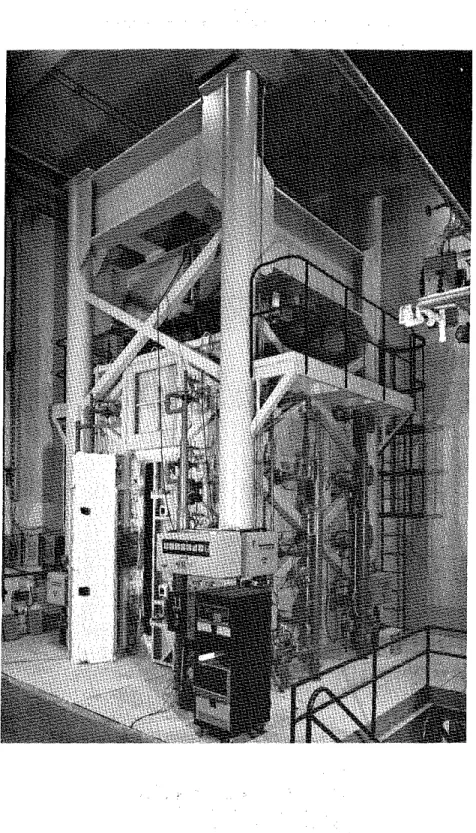
f u r n a c e s p e c i a l l y b u i l t f o r t e s t i n g loaded columns and walls. The t e s t f u r n a c e was designed t o produce t h e c o n d i t i o n s t o which a member might be exposed d u r i n g a f i r e , i . e . t e m p e r a t u r e s , s t r u c t u r a l l o a d s , and h e a t t r a n s f e r . It c o n s i s t s of a s t e e l framework s u p p o r t e d by f o u r s t e e l columns, w i t h t h e f u r n a c e chamber i n s i d e t h e framework ( F i g . 7 ) . The c h a r a c t e r i s t i c s and i n s t r u m e n t a t i o n of t h e f u r n a c e a r e d e s c r i b e d i n d e t a i l i n r e f e r e n c e 5. Only a b r i e f d e s c r i p t i o n of t h e f u r n a c e and t h e main components w i l l be g i v e n h e r e .
Loading Device
Three h y d r a u l i c j a c k s produce f o r c e s a l o n g t h e t h r e e p r i n c i p a l a x e s . The j a c k a c t i n g along t h e a x i s of t h e t e s t column i s l o c a t e d a t t h e bottom of t h e f u r n a c e chamber. The p l a t e on t o p of t h i s j a c k can be used a s a p l a t f o r m t o which t h e column can be a t t a c h e d .
Furnace Chamber
The f u r n a c e chamber has a f l o o r 2642 mm ( 8 f t 8 i n . ) on each s i d e and i s 3048 mm (10 f t ) high. I t i s made of i n s u l a t i n g m a t e r i a l s t h a t w i l l produce a h i g h h e a t t r a n s f e r t o t h e specimen. There a r e 32 propane gas b u r n e r s i n t h e f u r n a c e chamber, a r r a n g e d i n e i g h t columns c o n t a i n i n g f o u r b u r n e r s each. The t o t a l c a p a c i t y of t h e b u r n e r s i s 4700 kW (16 m i l l i o n B t u l h ) . Each b u r n e r can be a d j u s t e d i n d i v i d u a l l y , which a l l o w s a h i g h t e m p e r a t u r e u n i f o r m i t y i n t h e f u r n a c e chamber. The p r e s s u r e i n t h e f u r n a c e chamber i s a l s o a d j u s t a b l e . I t was s e t
somewhat lower t h a n a t m o s p h e r i c p r e s s u r e . I n s t r u m e n t a t i o n
The f u r n a c e t e m p e r a t u r e s a r e measured w i t h t h e a i d of e i g h t chromel-alumel thermocouples. The j u n c t i o n of e a c h thermocouple was l o c a t e d 305 mm ( 1 f t ) from t h e t e s t specimen,
a t
v a r i o u s h e i g h t s . Two thermocouples a r e p l a c e d o p p o s i t e each o t h e r every 610 mm (2 f t ) a l o n g t h e h e i g h t of t h e f u r n a c e chamber. The l o c a t i o n of t h e i r j u n c t i o n s and t h e i r numbering a r e shown i n F i g . 8 . Thermocouples No. 4 and 6 were l o c a t e d a t a h e i g h t of 610 mm (2 f t ) from t h e f l o o r , thermocouples No. 2 and 8 a t 1220 mm (4 f t ) , thermocouples No. 3 and 5 a t 1830 mm( 6 f t ) and thermocouples No. 1 and 7 a t 2440 mm ( 8 f t ) . The
t e m p e r a t u r e s measured by t h e thermocouples a r e averaged a u t o m a t i c a l l y and t h e a v e r a g e t e m p e r a t u r e used a s t h e c r i t e r i o n f o r c o n t r o l l i n g t h e f u r n a c e t e m p e r a t u r e .
The l o a d s a r e c o n t r o l l e d and measured w i t h t h e a i d of p r e s s u r e t r a n s d u c e r s . The a c c u r a c y of c o n t r o l l i n g and measuring l o a d s i s about 20 kN ( 5 k i p s ) a t lower load l e v e l s and b e t t e r a t h i g h e r l o a d s .
The a x i a l d e f o r m a t i o n of t h e t e s t specimen i s determined by measuring t h e displacement of t h e j a c k t h a t s u p p o r t s t h e column. The displacement is measured w i t h t h e a i d of t r a n s d u c e r s w i t h an accuracy of 0.002 mm (7.87 x 10⁻⁵ i n . ) .
Test
Conditions and Procedure
The column was i n s t a l l e d i n t h e f u r n a c e by b o l t i n g i t s end p l a t e s t o a l o a d i n g head a t t h e t o p and a h y d r a u l i c j a c k a t t h e bottom. E i g h t 19 mm ( 3 / 4 i n . ) b o l t s , spaced r e g u l a r l y around t h e column 63.5 mm
( 2 112 i n . ) from t h e s i d e s were used a t each end.
On t h e day of t h e test, t h e moisture c o n d i t i o n i n t h e c e n t e r of t h e column was measured w i t h a Monfore gauge3. The r e l a t i v e humidity p r i o r t o t h e s t a r t of t h e t e s t was 74%. The ambient t e m p e r a t u r e a t t h e s t a r t of t h e t e s t was 22-C (74'F).
The column was c a s t on t h e 1st of August 1977 and t e s t e d on t h e 1 1 t h of J u l y 1980. It was s u b j e c t e d t o a l o a d of 1067 kN (240 k i p s ) , which was a p p l i e d about one hour p r i o r t o t h e t e s t .
The c y l i n d e r s t r e n g t h of t h e c o n c r e t e on t h e t e s t d a t e , measured on two c y l i n d e r s , was 36.8 MPa (5332 p s i ) and 35.4 MPa (5129 p s i ) .
During t h e t e s t t h e column was exposed t o h e a t i n g c o n t r o l l e d s o t h a t t h e average t e m p e r a t u r e i n t h e f u r n a c e followed a s c l o s e l y a s p o s s i b l e t h e A S T M - E ~ I ~ ~ o r ULC-~101' s t a n d a r d temperature-time curve. T h i s curve can be a p p r o x i m a t e l y d e s c r i b e d by t h e f o l l o w i n g e q u a t i ~ n : ~ where Tf = t e m p e r a t u r e i n "C, and T
-
time i n h where Tf = t e m p e r a t u r e i n OF.During t h e t e s t , t e m p e r a t u r e s i n t h e f u r n a c e and i n t h e column were measured a t t h e l o c a t i o n s d e s c r i b e d e a r l i e r . The a x i a l s t r a i n of
and t h e t e s t was t e r m i n a t e d , when t h e h y d r a u l i c j a c k , which has a maximum speed of 76 mm/min ( 3 in./min), could no l o n g e r m a i n t a i n t h e a p p l i e d l o a d .
TEST. ReSULTS
Measured Temperatures and S t r a i n s
I n Table 2 t h e s t e e l temperatures a r e g i v e n f o r v a r i o u s times. The t e m p e r a t u r e s measured i n t h e c o n c r e t e s e c t i o n s a r e l i s t e d i n T a b l e s 3A-D.
I n Table 4 t h e a v e r a g e f u r n a c e t e m p e r a t u r e s a r e g i v e n and i n T a b l e 5 t h e measured a x i a l deformation of t h e column, f o r v a r i o u s times d u r i n g t h e t e s t .
O b s e r v a t i o n s
The o b s e r v a t i o n s made d u r i n g t h e t e s t a f t e r v a r i o u s exposure t i m e s a r e g i v e n below.
0:31 Four v e r t i c a l c r a c k s (A, B , C , and D
-
F i g . 9) 100 t o 150 mm ( 4 t o 6 i n . ) l o n g appeared on t h e e a s t f a c e of t h e column. 0:56 A new crack ( E ) formed 100 nun ( 4 i n . ) below c r a c k A on t h esame column f a c e .
1:05 A l o n g v e r t i c a l c r a c k (F) on t h e n o r t h f a c e , and a r e l a t i v e l y l o n g h a i r l i n e c r a c k ( G ) on t h e west f a c e were observed.
1:07 Cracks A and E extended and j o i n e d t o g e t h e r t o form a l o n g c r a c k (AE).
1:15 Crack F widened.
1:33 Crack
AE
widened t o about 1.5 mm (1116 i n . ) . A t t h i s time,t h e c o n c r e t e t e m p e r a t u r e n e a r t h e exposed s u r f a c e was about 760°C (1400°F) and 1150°C (240°F) a t t h e c e n t e r . The s t e e l t e m p e r a t u r e was n e a r 427°C (800°F), and t h e column expanded 6 mm (114 i n . ) .
1:50 S e v e r a l h a i r l i n e c r a c k s were v i s i b l e on t h e s o u t h f a c e . Crack AE on t h e e a s t f a c e doubled i n w i d t h t o about 3 mm
(118 i n . ) .
2:12 Column expansion due t o h e a t i n g reached i t s maximum and s t a b i l i z e d .
2:41 H a i r l i n e c r a c k s on s o u t h f a c e were v i s i b l e .
3:04 Crack AE on t h e e a s t f a c e had a 6 mm (114 i n . ) width. 3:07 Zero column expansion was r e c o r d e d .
3:13 E l e c t r i c a l power was l o s t , due t o a s e v e r e thunderstorm. Gas t o b u r n e r s was a u t o m a t i c a l l y s h u t o f f .
3:15 Power was back on and f i r e resumed. Cracks on s o u t h f a c e appeared t o be about 10 mm (318 i n . ) wide and c r a c k AE on t h e e a s t f a c e about 13 mm (112 i n . ) .
3:28 The h y d r a u l i c p r e s s u r e suddenly dropped from 2172 kPa (315 p s i ) t o 690 kPa (100 p s i ) .
Column f a i l e d .
F a i l u r e of t h e column i n t h i s t e s t was due t o c r u s h i n g of c o n c r e t e and b u c k l i n g of s t e e l . F i g u r e 9 shows t h e g e n e r a l l o c a t i o n of t h e c r a c k s i n t h e column a t two hours t e s t time. F i g u r e 10 g i v e s a
s c h e m a t i c view of t h e column a t t h e end of t h e t e s t . F i g u r e 11 shows a p i c t u r e of t h e column i n t h e f u r n a c e chamber a f t e r t h e t e s t .
DISCUSSION OF RESULTS
Using t h e method d e s c r i b e d i n r e f e r e n c e 9, t h e t e m p e r a t u r e s of t h e main r e i n f o r c i n g s t e e l , and t h e t e m p e r a t u r e s a t v a r i o u s d e p t h s i n t h e c o n c r e t e s e c t i o n s , have been c a l c u l a t e d . For t h e r e i n f o r c i n g s t e e l t h e t e m p e r a t u r e a t t h e c e n t e r h a s been chosen a s r e p r e s e n t a t i v e of t h e a v e r a g e t e m p e r a t u r e of t h e s t e e l .
F i g u r e 12 shows two a v e r a g e t e m p e r a t u r e s o b t a i n e d from measurements on two r e i n f o r c i n g b a r s d u r i n g t h e t e s t . These
measurements were made w i t h thermocouples No. 3 and 9, l o c a t e d o p p o s i t e each o t h e r w i t h r e s p e c t t o t h e c e n t e r of one b a r , and w i t h
thermocouples No. 4 and 1 0 , l o c a t e d o p p o s i t e each o t h e r on a n o t h e r b a r ( F i g . 6 ) .
The t e m p e r a t u r e s measured on t h e s t e e l by t h e i n d i v i d u a l thermocouples a r e shown i n Fig. 13. The d i f f e r e n c e i n t e m p e r a t u r e between two o p p o s i t e p o i n t s of a b a r i s r e l a t i v e l y s m a l l .
I n Fig. 1 4 , t h e t e m p e r a t u r e s shown a r e measured a l o n g a c e n t e r l i n e i n t h e c o n c r e t e s e c t i o n a t mid-height, a t v a r i o u s d e p t h s . The curves show a f a i r l y good agreement between measured and c a l c u l a t e d
t e m p e r a t u r e s .
F i g u r e 15 shows a x i a l d e f o r m a t i o n a s a f u n c t i o n of time d u r i n g e x p o s u r e t o a s t a n d a r d f i r e . The measured a x i a l s t r a i n d u r i n g t h e t e s t , and t h o s e c a l c u l a t e d u s i n g t h e method d e s c r i b e d i n r e f e r e n c e 9 ,
a r e shown. The c a l c u l a t e d f a i l u r e time is 178 minutes, which i s about 1 5 percent l e s s t h a n t h e measured f a i l u r e time.
The comparison of measured and c a l c u l a t e d t e m p e r a t u r e s and s t r a i n s shows t h a t t h e p r e d i c t i o n s l i e on t h e s a f e s i d e . The d i f f e r e n c e s
between p r e d i c t e d and measured v a l u e s a r e r e l a t i v e l y s m a l l , w i t h t h e e x c e p t i o n of t h a t between measured and c a l c u l a t e d f a i l u r e t i m e s . T h i s d i f f e r e n c e however, of which a p a r t was caused by t h e i n t e r r u p t i o n of h e a t supply i n t h e f u r n a c e d u r i n g t h e t e s t , i s not s i g n i f i c a n t .
I REFERENCES
Standard Practice for Petrographic Examination of Aggregates for
Concrete (1979). ASTM C295-79, American Society for Testing and
Materials, Philadelphia, PA.
Standard Specification for Deformed and Plain Bullet-Steel Bars for
Concrete Reinforcement (1980).
ASTM A615-80, American Society for
Testing and Materials, Philadelphia, PA.
Monfore, G.E. (1962). A Small Probe-Type Gauge for Measuring
Relative Humidity. Journal of the PCA Research and Development
Laboratories, Vol. 5, No. 2.
Reinforcing Steel Welding Code (1975).
AWS-D12.1-75, American
Welding Society, Manlius,
NY.Lie, T.T. (1980).
New Facility to Determine Fire Resistance of
Columns, Canadian Journal of Civil Engineering, Vol. 7, No.
3.Standard Methods of Fire Tests of Building Construction and
Materials (1979).
ANSI/ASTM E119-79, American Society for Testing
and Materials, Philadelphia, PA.
Standard Methods of Fire Endurance Tests of Building Construction
and Materials (1980).
ULC-S101-M1980. Underwriters' Laboratories
of Canada, Scarborough, Ontario.
Lie, T.T. and Harmathy, T.Z. (1972).
A Numerical Procedure to
Calculate the Temperature of Protected Steel Columns Exposed to
Fire. Fire Study No. 28, Division of Building Research, National
Research Council of Canada, Ottawa. Ontario, NRCC 12535.
Lie, T.T., Allen, D.E., Lin, T.D. and Abrams, M.S.
Fire Resistance
of Reinforced Concrete Columns, Division of Building Research,
National Research Council Canada, Ottawa, to be published.
TABLE 1 PETROGRAPHY OF SAND AND GRAVEL USED AS AGGREGATE
-- -
Composition of Sieve Fraction, Percent on Sieve of Size Indicated Percent
Component Passing
19 mm 12.5 mm 9.5 mm 6 mm No. No. No. Bo
.
No. No. No. through4 8 16 30 50 100 200 No. 200 Granite 37.9 32.9 25.5 31.3 27 .O 27.6 12.3 7.4 1.9 4.4 0.6
--
Quartzite 21.6 29.2 34.8 24.6 24.5 20.0 12.3 12.6 10.9 3.1 2.2--
Quartz 6.3 3.1 4.9 4.8 5.5 18.8 52.2 62.0 73.1 79.5 74.2 92.0 Sandstone-Quartz Conglomrate 1.9 0.8 3.1 5.1 5.5 8.3--
--
--
--
--
--
Rhyolite-Dacite 13.9 6.2 2 -2 5.1 7.2 4.1 0.8 2.6 1.6 0 -8 0.9--
Feldspar-
-
-
-
-
-
1.3 5.0 6.6 5.0 10.8 4.0 Diorite 1.9 1.4 3.1 1.8 1.2--
--
-
--
--
-
-
Graywacke b 1.3 9.5 5.8 5.4 4.3 6.5 2.3 1.5 0.3--
0.6--
Gneiss-Schist 2.5 5.1 10.5 9.3 7.5 4.1 6.4 1.8 0.9 1.1 0.6--
Basalt 1.9 4.5 4 .O 3.9 6.9 3.2 2.6 2.4 0.7-
0.3--
Mist. Igneous Rocks and Opaque Minerals--
0.3 0.9 0.6 0.6 1.5 2.1 1.2 2.0 5.3 7.0 2.0Particle Shape 19 to 6 mm ( X ) No. 4 to No. 16 (%) No. 30 to No. 200 (%)
Subrounded to rounded 30 20 10
Subrounded to subangular 40 40 40
Angular 30 40 5 0
a"~ronstone," made up of jasper and hematite, is included in the chert classification. blncludes metagraywacke.
?he miscellaneous igneous rocks were severely altered and positive identification was impossible. The opaque minerals occurred in the No. 50 and smaller sieve sizes and were largely magnetite.
TABLE 2 MEASURED STEEL TEMPERATURES Temperature ( O C ) Measured a t Thermocouple No: T i m e ( m i d 1 2 3 4 5 6 7 8 9 10 0 22 22 22 22 21 21 22 22 22 22 5 26 27 26 25 25 24 32 3 5 24 23 10 47 5 1 47 38 42 39 68 72 38 31 1 5 102 107 92 81 92 8 9 108 108 74 5 8 20 124 120 120 117 120 124 128 1 2 1 120 97 2 5 116 123 120 117
*
*
157 150 114 109 30 122 142 130 119 126 126 196 170 118 111 3 5 139 169 151 137 145 146 230 196 134 119 40 163 197 177 158 168 170 258 222 157 133 4 5 189 225 204 181 193 196 283 243 182 150 50 215 253 229 204 218 221 306 265 205 170 5 5 240 279 254 227 243 246 327 287 229 191 60 265 305 279 250 267 270 347 308 252 213 7 0 311 353 324 295 313 315 384 345 295 256 80 353 396 365 336 354 355 417 380 335 295 9 0 391 435 402 375 392 392 448 415 371 333 100 427 472 437 411 428 427 477 446 404 368 110 462 505 471 447 461 459 503 473 437 401 120 494 534 502 480 492 489 528 499 467 433 130 524 560 531 510 520 518 551 527 496 463 140 550 585 557 536 546 543 577 554 523 491 150 577 610 586 562 573 568 602 581 548 516 160 603 634 616 586 599 592 626 608 575 539 170 628 656 650 611 527 616 649 639 601 563 180 651 676 684 637 657 638 671 676 625 588 190 673 698 710 663 689 660 693 709 650 611 200 696 715 7 2 1 689 714 681 710 721 678 633 207 710 724*
648*
772 717 721 695 759 XMeasurement n o t r e l i a b l eTABLE 3A CONCRETE TEMPERATURES MEASURED WITH THERMOCOUPLES I N FRAME A Time ( m i d 0 5 Temperature ( O C ) Measured a t Thermocouple No: 11 12 13 14 15 16 17 18 19 20 21 22 23 24 21 22 22 22 22 22 22 22 22 22 22 22 22 22 113 78 44 30 23 22 22 22 2 3 50 62 101 159 220 203 142 91 58 30 23 22 23 33 72 132 194 305 400 300 214 120 93 47 25 22 27 8 0 120 1 9 9 298 435 532 370 277 163 115 68 33 24 51 116 142 274 380 514 602 439 336 206 136 94 55 33 74 118 172 334 443 579 670 497 387 246 164 109 77 40 79
*
227 391 502 642 727 541 430 282 191 118 90 49 54 119 278 445 552 693 763 567 461 313 215 127 104 60 92 133 320 491 595 720 7 8 1 601 491 339 236 137 108 72 97 153 355 529 634 740 812 628 518 364 256 147 111 84 104 174 386 562 672 761 831 645 538 386 275 159 112 93 112 195 413 595 692*
841 668 558 406 292 173 117 101 118 216 438 623 699*
859 699 594 442 322 200 129 116 132 256 481 671 712*
*
726 622 471 349 226 140 121 145 291 517 707 741 770*
752 650 500 377 252 154 123 162 325 547 739 761 784*
780 680 530 406 278 172 130 185 359 579 769 776 790*
797 703 557 435 305 194 139 210 392 608 793 780*
x 821 728 585 464 332 216 157 236 424 634 813 785*
x 839 751 612 492 358 240 182 262 455 659 832 788*
*
855 771 638 518 384 266 210 288 484 681 848 788*
*
870 789 660 542 410 292 237 315 511 702 863*
*
*
885 807 682 565 435 318 263 340 535 721 877*
x*
898 824 703 588 459 342 289 365 559 740 890*
x*
*
838 722 610 483 366 314 389 583 758 902*
k*
*
846 741 632 505 390 339 415 607 774*
x x*
*
*
744 651 528 415 369 450 628 787*
x x*
*Measurement not r e l i a b l eTABLE 3B CONCRETE TEMPERATURES MEASURED WITH THERMOCOUPLES I N
FRAME
B- - -
Temperature (OC) Measured a t
Thermocouple No: Time (min) 25 26 27 28 29 30 31 32 3 3 34 35 36 37 3 8 0 21 21 21 21 21 21 21 22 21 21 22 22 22 22 5 125 89 47 32 23 22 2 1 22 2 3 30 61 91 159 212 10 227 163 99 61 30 22 21 22 31 65 131 179 312 397 1 5 329 246 136 96 46 25 22 26 75 112 198 281 443 532 20 391 307 180 121 65 32 24 48 110 133 269 362 519 602 25 456 367 226 145 93 46 29 70 115 167 331 428 586 669 30 522 423 269 170 109 63 38 70
*
221 391 492 649 726 3 5 567 469 308 200 117 85 51 76*
218 442 543 697 1674 40 590 496 338 226 124 98 72 93 117 289 484 584 722*
45 625 528 366 250 138 105 8 7 102 138 335 522 623 757*
50 654 556 393 273 155 107 94 107 162 368 557 661 783*
5 5 672 577 417 296 172 108 98 110 1 8 6 397 591 689 798*
60 698 600 439 317 189 110 101 115 209 422 619 714 820*
7 0 730 637 480 358 222 118 107 127 254 466 669 754 849*
80 761 670 516 394 254 131 118 142 296 503 705 784 863*
9 0 789 700 549 428 282 147 127 162 334 537 737 813*
*
100 814 730 581 459 306 167 134 185 369 569 766 837*
x 110 829 750 608 487 329 187 142 209 402 599 786*
x x 120 852 774 633 513 356 209 155 234 433 624 805*
*
*
1 3 0 868 794 657 539 385 234 179 261 463 648 822*
*
x 140 882 812 680 564 413 262 210 288 491 669 837*
x x 150 893 828 700 589 440 290 239 315 516 690 844*
*
*
160*
845 720 612 465 317 266 341 540 709*
x*
r~ 170*
860 738 635 489 343 295 367 564 728*
*
r~ x 180*
873 756 656 512 372 340 392 588 743*
*
*
*
190*
888 772 672 543 418 438 424 612 752*
*
IL*
200 k x*
689 594 504 566 486 639*
x*
x*
*Measurement n o t r e l i a b l eTABLE 3C CONCRETE TEMPERATURES MEASURED WITH THERMOCOUPLES I N FRAME C
Temperature ( OC) Measured a t Thermocouple No:
Time
(min) 39 40 41 4 2 43 44 45 46 47 48 49 50 51 52
TABLE 3D CONCRETE TEMPERATURES MEASURED WITH THERMOCOUPLES I N FRAME D
Temperature ( OC) Measured a t
Thermocouple No: Time (min) 53 54 55 56 57 58 59 60 61 62 63 64 6 5 66 0 21 21 21 2 1 21 21 2 1 22 22 22 22 22 22 22 5 115 79 46 32 24 23 2 3 22 23 32 62 104 160 212 10 212 144 90 57 3 1 23 23 22 31 71 133 202 314 395 1 5 314 218 124 92 44 26 2 3 25 66 119 200 313 450 529 20 374 269 165 107 63 34 27 45 112 139 271 394 527 599 25 429 316 205 133 94 63 47 71 116 188 331 459 592 664 30 489 367 241 155 103 72 5 1 80
*
247 393 522 655 720 35 535 411 276 1 7 8 106 77 56 8 3*
297 449 574 701 758 40 560 442 306 202 116 8 3 65 88 122 340 497 617 727 777 45 595 474 333 224 129 90 8 3 9 3 139 375 535 657*
805 50 620 502 358 245 142 100 93 103 158 406 571*
748*
55 637 523 380 264 156 109 1 0 1 108 177 433 604*
757*
60 659 544 399 282 169 114 107 111 196 456 632 660 770*
70 686 575 433 313 193 122 113 123 235 498 679 725 771*
80 715 605 461 341 217 133 120 140 274 532 714 751 788*
90 741 634 491 370 242 149 128 164 310 564 744 768 797*
100 767 664 521 399 269 170 135 189 344 595 773 773*
*
110 784 687 548 429 297 194 145 213 377 625 795*
x*
120 810 714 577 458 324 219 164 239 409 651 815*
*
x 130 830 727 591 472 338 232 178 252 425 665 825*
x*
140 850 764 634 516 380 272 222 292 470 665 841*
846*
150 866 785 661 542 407 298 249 319 500 681 853*
860*
160 883 804 684 568 434 324 275 345 529 697 862*
885*
170 896 820 706 593 459 349 300 370 557 711*
*
*
*
180 905*
725 617 482 373 324 396 590 717*
x k x 190 917*
744 640 505 396 347 427 619 719*
k*
*
200*
*
745 657 527 418 370 476 642 723*
*
x*
*Measurement n o t r e l i a b l eTABLE 4 AVERAGE FURNACE TEMPERATURE
T i m e T e m p e r a t u r e T i m e T e m p e r a t u r e T i m e T e m p e r a t u r e ( m i d ("C) ( m i d ("C) ( m i d ("C)
TARLE 5 MEASURED AXIAL DEFORMATION OF COLUMN
Time Deformation Time Deformation Time Deformation
(min) (mm) ( m i d (nun) ( m i d (mm) 0 0 60 4.1 160 4.2 5 0.3 75 5.0 165 3.5 10 0.7 90 5.7 170 2.8 15 1.4 10 5 6.0 176 1.9 20 2.3 120 6 .O 180 1.4 2 7 2.6 12 5 6.0 185 0.4 30 2.7 130 5.9 190 -0.4 35 2.8 13 5 5.8 19 5 -1.8 40 3.0 140 5.5 200 -4.0 45 3.4 145 5.3 205 -4.7 50 3.7 150 5 .O 5 5 4.0 155 4.6
-
s i g n i n d i c a t e s c o n t r a c t i o n of column p a s t i n i t i a l s t a r t i n g p o s i t i o nm m m m m m
S T A N D A R D S I Z E O F S Q U A R E M E S H S I E V E
F I G U R E 1
F I G U R E 2
TIC
F R A M E A
A
A L
S E C T I O N A - A
TIC
F R A M E B
O N B A C K
TIC
F R A M E
CO N F R O N T
S E C T I O N B - B
--
TIC
F R A M E
D-,
c
S E C T I O N C - C
T / C
F R A M E
F I G U R E
3L A Y O U T O F T H E R M O C O U P L E F R A M E S
TIC
FRAME 17 16 15 14 13 12 11 A 31 30 29 28 27 26 25 B 45 44 43 42 41 40 39 C 59 58 57 56 55 54 53D
F I G U R E 4 L O C A T I O N A N D N U M B E R S O F T H E R M O C O U P L E SI N A
S E C T I O N48 mm CLEAR COVER TO TIC 4, 5, 6, 10
&:
,REI~~~CING BAR4 25 M BAR
I_
TIC 1, 2, 3, 9 305 mm533 x 533 x 25 mm
THICK STEEL PLATE
7
1F I G U R E 5
F I G U R E 6
T H E R M O C O U P L E S O N R E I N F O R C I N G B A R S ( 3 0 5 m m x 3 0 5 m m C O L U M N )
FIGURE 7 TEST FURNACE
T O P V I E W
7
D O O R ( E A S T S I D E ) F I G U R E 8 L O C A T I O N A N D N U M B E R S O F T H E R M O C O U P L E S I N C O L U M N F U R N A C E C H A M B E RE
1 0 0 - 1 5 0 m m G 1 0 0 m m L O N G 1 0 0 m m F R O M EDGE H A I R L I N E C R A C K S N O R T H F L O O R S O U T H F I G U R E 9 C R A C K S I N C O L U M N A T 2 h T E S T T I M EF I G U R E 10
FIGURE 11
I