HAL Id: hal-01907317
https://hal.archives-ouvertes.fr/hal-01907317
Submitted on 29 Oct 2018
HAL is a multi-disciplinary open access
archive for the deposit and dissemination of
sci-entific research documents, whether they are
pub-lished or not. The documents may come from
teaching and research institutions in France or
abroad, or from public or private research centers.
L’archive ouverte pluridisciplinaire HAL, est
destinée au dépôt et à la diffusion de documents
scientifiques de niveau recherche, publiés ou non,
émanant des établissements d’enseignement et de
recherche français ou étrangers, des laboratoires
publics ou privés.
Hydrodynamics and mixing in continuous oscillatory
flow reactors-Part II: Characterisation methods
Alex Mazubert, David Fletcher, Martine Poux, Joelle Aubin
To cite this version:
Alex Mazubert, David Fletcher, Martine Poux, Joelle Aubin. Hydrodynamics and mixing in
continu-ous oscillatory flow reactors-Part II: Characterisation methods. Chemical Engineering and Processing:
Process Intensification, Elsevier, 2016, 102, pp.102-116. �10.1016/j.cep.2016.01.009�. �hal-01907317�
O
pen
A
rchive
T
oulouse
A
rchive
O
uverte
(OATAO)
OATAO is an open access repository that collects the work of some Toulouse
researchers and makes it freely available over the web where possible.
This is an author’s version published in:
http://oatao.univ-toulouse.fr/
20508
Official URL:
https://doi.org/10.1016/j.cep.2016.01.009
To cite this version:
Mazubert, Alex and Fletcher, David and Poux, Martine and Aubin, Joelle
Hydrodynamics and mixing in continuous oscillatory flow reactors—Part II:
Characterisation methods. (2016) Chemical Engineering and Processing: Process
Intensification, 102. 102-116. ISSN 0255-2701
Any correspondance concerning this service should be sent to the repository administrator:
[email protected]
Hydrodynamics
and
mixing
in
continuous
oscillatory
flow
reactors—Part
II:
Characterisation
methods
A.
Mazubert
a,b,
D.F.
Fletcher
c,
M.
Poux
a,b,
J.
Aubin
a,b,*
aUniversityofToulouse,INPT/UPS,LaboratoiredeGénieChimique,4AlléeEmileMonso,BP-31243,31432Toulouse,France bCNRS,LaboratoiredeGénieChimique,31432Toulouse,France
cSchoolofChemicalandBiomolecularEngineering,TheUniversityofSydney,NSW2006,Australia
Keywords: Mixing
Processintensification Oscillatorybaffledreactors Oscillatoryflow
ABSTRACT
Thisworkpresentsandexploitsquantitativemeasurestobetterquantifytheperformanceofoscillatory baffled reactors, being complementary to simple vector plots and shear strainrate fields. Novel performancecriteria,includingradialandaxialfluidstretchingandmixing,aswellastheshearstrain ratehistoryoffluidelementshavebeendevelopedandusedtocomparetheperformanceoffivedifferent baffledesigns,namelysingleorificebaffles,disc-and-donutbafflesandthreenovelvariationsofhelical blades.Analysisofresidencetimedistributionshasalso beenusedtoevaluatethegeometries.The performancemeasureshighlightthatthedisc-and-donutbafflescanprovidesignificantshearstrain rates,whichcouldbeusefulformultiphaseapplications,butalsosignificantaxialdispersionthatis comparablewiththatforthesingleorificebaffles.Theresultsalsosuggestthathelicalbladedesigns couldbepromisingfordecreasingaxialdispersion,whilstmaintainingsignificantlevelsofshearstrain rate.
1.Introduction
In Part I of this series [1], time-resolved laminar CFD simulationshavebeenperformedtostudytheflowgeneratedin fiveoscillatorybaffledreactor(OBR)designs,threeofwhichare novelcomparedwiththesingleorificebafflesordisc-and-donut bafflesthathavebeentraditionallyusedforthistypeofdevice.The flowgeneratedbythesedesignshasbeenassessedbyexamining instantaneousvelocityfields,shearstrainratefieldsandpressure drop.
This study highlighted the complex flow behavior and the formationofvorticesinthereactorduetobothflowblockageby thebaffledesignandflowreversal.Indeed,dependingonthebaffle geometry,thereismoreorlessfluidrecirculation,dominantaxial flow and shearstrainratevariation.The disc-and-donutbaffles generatemultiplevorticesandthehelicalbladedesignscreatea complex3Dflowwithasignificanttransversecomponent.Interms of shear strain rates, which are of interest for multiphase applications, the disc-and-donut baffles and the helical blade bafflesprovidethehighestvalues,whicharemorethantwotimes greater than those generated by the singleorifice design. It is
interestingtonote howeverthatthemaximum strainratesare localisedandoccupyrelativelysmallvolumesinthereactor;only thedisc-and-donutbafflesprovidesubstantialspatialvariationof shearstrainrate. Thismeansthatonly asmall amountof fluid passingthroughthereactormayexperiencehighshearstress.The workalsoshowed that thebaffledesign hasa huge impacton pressuredrop,whichisasexpected.The disc-and-donutdesign causesthehighestpressuredrop,whichisgreaterbyaboutafactor offivethanthatwiththesingleorificebaffles.Thepressuredrop generatedbyhelicalbafflesisapproximatelyhalfthatofthe disc-and-donutdesign. Indeed,althoughtheensembleoftheresults provide knowledge on the flow mechanisms and operating characteristicsofOBRs,it isclearly difficulttoconcludeonthe impactofbaffledesign ontheperformanceof thereactorwith velocityandshearstrainratesalone.
As previously reported in the introduction of Part I, the majority of the studies in the literature describe the flow generatedinOBRsinaqualitativemannerusingplanarvelocity fieldsandvelocityprofiles[2–5]orshearstrainratefields[6].A significant number of studies have also evaluated the perfor-mance ofOBRs interms of axial dispersion viatheanalysis of residencetimedistributions [7–13].The generalobservationof these studies is that for oscillatory Reynolds numbers (ReO)
greaterthanapproximately200,theaxialdispersioncoefficient increaseslinearlywhenwithincreasingReO,beingproportional
* Corresponding author at: CNRS, Laboratoire de Génie Chimique, 31432 Toulouse,France.
totheproductA.f.ForReO<200,however,adecreaseinReOalso
causes an increase in theaxial dispersioncoefficient such that thereisaminimumaxialdispersionasafunctionofReO.Smithand
Mackley [9] explain the minimum in the axial dispersion
coefficientduetotheinteractionofnetflowandoscillatoryflow wherebysignificantradialmixingisgeneratedwithoutexcessive axialmixing. Theyhavealsoshownthat anincreaseof thenet Reynolds number (Renet) also causes an increase in the axial
dispersioncoefficient.
The main objective of this paper is to develop alternative methodsthatallowOBRstobecharacterisedandassessedinterms ofdifferentperformancecriteria:radialandaxialfluidstretching andmixing,andshearstrainratehistory.Theperformanceofthese methods is then demonstrated using the five different reactor geometries presented in Part 1. A Lagrangian particle tracking methodhasalsobeenusedtocarryoutananalysisoftheresidence timedistribution,whichcompletesvariousstudiesintheliterature
[9–12,14,15].
2. Flowcomputationandparticletracking
Themethodology usedtoperformtheflow simulationswas describedfullyinPart1ofthispaper[1].Inadditiontotheusual analysisoftheflowfieldvariableswealsoperformedLagrangian particle tracking to provide additional information. We used particleshavingthesamedensityasthefluidandadiameterof 1micronwhichhaveaStokesnumbersofO(10!5)andtherefore
followthefluidfaithfully.Withthismethodthereisnointeraction betweenparticlesandnophysicalandlittlenumericaldiffusion. TheLagrangianapproachintroducesnoartificialdiffusionandin Part I we showed the flow results are mesh and time-step independentsowecanreasonablyexpectthenumericaldiffusion in the velocity field to be very low. The particle behavior is determined by integration of the kinematic and momentum balanceequationsforeachparticle,whichtaketheform dy
dt¼v;mp dv
dt¼FD ð1Þ
whereyistheparticlelocation,vitsvelocity,tistime,mpisthe
massoftheparticleFDisthedragforce,whichwasmodeledusing
the Schiller Naumann model. These equations wereintegrated usingafourth-orderRunge–Kuttaschemewithadaptivestepsize. Alineofsuchparticleswasreleasedalongthetuberadiusata particularaxiallocation(X0),withtheirinitialvelocitysettothatof
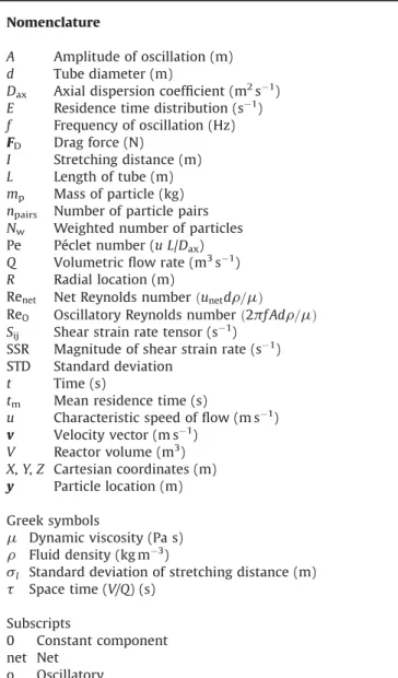
thelocal fluid velocity. The number ofinitial particlelocations alongthelinewassetat2484for2Dgeometriesand4968for3D geometries and this number of particles proved sufficient to characterisetheflow.Inadditiontorecordingtheparticletravel time,locationandvelocitycomponents,aparticlescalarwasused tostorethelocalstrainrateofthefluid.Attheendoftherundata Nomenclature
A Amplitudeofoscillation(m) d Tubediameter(m)
Dax Axialdispersioncoefficient(m2s!1)
E Residencetimedistribution(s!1)
f Frequencyofoscillation(Hz) FD Dragforce(N)
I Stretchingdistance(m) L Lengthoftube(m) mp Massofparticle(kg)
npairs Numberofparticlepairs
Nw Weightednumberofparticles
Pe Pécletnumber(uL/Dax)
Q Volumetricflowrate(m3s!1)
R Radiallocation(m)
Renet NetReynoldsnumberðunetd
r
=m
ÞReO OscillatoryReynoldsnumberð2
p
fAdr
=m
ÞSij Shearstrainratetensor(s!1)
SSR Magnitudeofshearstrainrate(s!1)
STD Standarddeviation t Time(s)
tm Meanresidencetime(s)
u Characteristicspeedofflow(ms!1)
v Velocityvector(ms!1)
V Reactorvolume(m3)
X,Y,Z Cartesiancoordinates(m) y Particlelocation(m) Greeksymbols
m
Dynamicviscosity(Pas)r
Fluiddensity(kgm!3)s
l Standarddeviationofstretchingdistance(m)t
Spacetime(V/Q)(s) Subscripts0 Constantcomponent net Net
o Oscillatory
foreachtrackwereexportedandgaveacompletehistoryofthe conditionsexperiencedbytheparticle,whichrepresentsthatof thefluidoriginatingattheinitiallocationoftheparticle. 3. Characterisationtechniques
3.1.Radialandaxialfluidstretching
Thistechniquefollowstheradialandaxialdistancesseparating twoinitiallyadjacentparticlesasafunctionoftime.Itisusedto quantify radialand axialmixing separately.Fluidelementsthat experiencesignificantstretchintheradialdirectionareinzonesof good radial mixing, whereas fluid elements with very little stretching experience poor radial mixing. Small stretching distancesintheaxialdirection,however,highlightnearplug-flow behavior.Ontheotherhandhighamountsofstretchingintheaxial flowdirectionsuggestawideresidencetimedistribution.
Calculations are performed for pairs of initially adjacent particles.Thetimeevolution ofthedistanceseparatingthepair ofparticlesisdeterminedateverytimestepfor50s.Theprinciple of the calculationsfor one pairofparticles is described bythe followingequationsandtheschematicdiagramgiveninFig.1.
At time t,
D
X=|XparticleA!XparticleB|, where X is the axialcoordinateoftheparticle.
D
X(t) is then integratedfor each pairof particles,giving an averagevalueofstretchingIDX:IDX¼ 1 tn Xtn i¼0
D
Xiþ1þD
Xi 2 ðtiþ1!tiÞ ð2ÞIDXistheaveragevalueofIDXforallparticlepairsandiscalculated as: IDX¼ 1 npairs X npairs j¼1 IDX j ð3Þ
andthestandarddeviation
s
Iis:s
I¼ ffiffiffiffiffiffiffiffiffiffiffiffiffiffiffiffiffiffiffiffiffiffiffiffiffiffiffiffiffiffiffiffiffiffiffiffiffiffiffiffiffiffiffiffiffiffiffiffiffiffiffiffiffiffi 1 npairs X npairs j¼1 IDXj # $2 !#IDXÞ2 v u u t ð4ÞAnanalogouscalculationis madefor stretchingin theradial directionR,whereR¼ ffiffiffiffiffiffiffiffiffiffiffiffiffiffiffiffiffiffiffiffiffiffi Y2þZ2 # $ r .
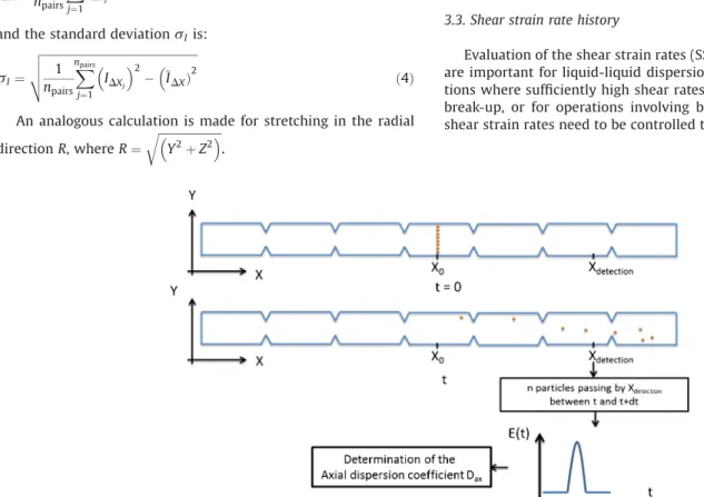
3.2.Residencetimedistribution
The RTD for the fluid flowing through the various OBR geometrieswascalculatedbydeterminingtheparticletrajectories andbyrecordingtheparticleresidencetimesoveradefinedlength of the OBR geometry. The residence time distribution, E(t), as describedbyFogler[16],isthencalculatedas:
EðtÞ¼
D
Nw Nw1
D
t ð5Þwhere
D
Nwisthenumberofparticlesthathavearesidencetimeinthereactorbetweentimetandt+
D
teachweightedbytheirinitial velocitynormalizedbythemaximumvelocityinthetube,andNwisthetotalweightnumberofparticlesreleasedinthereactor.This approachhasalreadybeensuccessfullyemployedforRTDanalysis incontinuousmicroreactorsbyAubinetal.[17].FromE(t),thefirst and second moments,i.e. the meanresidence time tmand the
variance
s
2RTD can be determined. For open systems the mean
residencetimeandthevariancearerelatedtothereactorPéclet numberPe,following:
s
2 RTD t2 m ¼ 2 Peþ 8 Pe2 ð6ÞThePécletnumberisdefinedas: Pe¼ uL
Dax
ð7Þ whereListhelengthofthetubeandDaxistheaxialdispersion
coefficient.TheprincipleofthedeterminationofPécletnumber and axial dispersion coefficient is illustrated in Fig. 2. The characteristiclengthLcorrespondstothedistancebetweenthe planewheretheparticlesarereleased(X=X0)andtheplanewhere
theresidencetimesofparticlesarerecorded(X=Xdetection).
3.3.Shearstrainratehistory
Evaluationoftheshearstrainrates(SSR)generatedintheOBR areimportantforliquid-liquiddispersionandemulsion applica-tionswheresufficientlyhighshearratesarerequiredfordroplet break-up, or for operations involving biological cultures where shearstrainratesneedtobecontrolledtoavoidcelldamage.The
Fig.2. ParticlesthatareevenlydistributedacrosstheradiusofthetubearereleasedatX0.ThenumberofparticlespassingXdetectionbetweenatdifferenttimesarerecordedto
shearstrainratetensorforanincompressiblefluidisgivenby: Sij¼ 1 2
@
ui@
xj þ@
uj@
xi ) * ð8Þ whichgivesthefollowingequationforthemagnitudeoftheshear strainrate: SSR¼ 2@
ui@
xj Sij + ,1=2 ð9Þ Although local values of shear strain rate can be directly obtainedfromtheCFDsimulations,theydonotprovidestatistical information on the duration and volume of the flow that experiences different ranges of shear rates. This can be done howeverbyfollowingtheshearstrainrate experiencedbyeach tracerparticleonitstrajectorythroughthereactor.Ateverytime step,thestrainratemagnitudeisrecordedforeachparticle.The maximumstrainrateandtheaveragestrainrateforeachparticle overtimearethencalculated.Finally,theglobalmeanstrainrate experiencedbytheensembleofparticlesisdetermined.4.Verificationofcharacterisationmethods
Inadditiontoverifyingthatthesolutionismeshindependent, whichwasshowninPartIofthisstudy[1].theindependencyof theperformancecharacteristics(determinedbyparticletracking techniques)onmesh sizeand thenumber of trackingparticles usedwasalsochecked.Theeffectoftheseparameters,aswellas thereactorlengthandtheinjectionpositionofthetracerparticles, onfluidstretching,theaxialdispersioncoefficientandthestrain ratehistorywereinvestigated.
4.1.Influenceofthemeshsize
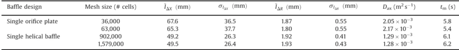
The influence of the mesh size on radial and axial fluid stretchingandonresidencetimedistributioncalculatedintheOBR withsingle orifice plates and with a single helical baffle with A=16.5mmandf=1.05HzispresentedinTable1.Theresultsshow thatthemeanvaluesofradialandaxialstretching,aswellastheir standarddeviation,andtheaxialdispersioncoefficientandmean residence time hardly vary when computed on the different meshes. The relative difference of the values obtained on the differentmeshesarebelow6%forthe2-dimensionalmeshusedfor theorificeplategeometryandlessthan1%forthe3-dimensional meshusedforthesinglehelicalbafflereactor.Moreover,themesh size has also shown to have no influence on the average and maximumparticlestrainrates,and thestandard deviation;the relativedifferencesof thesevaluescalculatedondifferentmesh sizesislessthe0.4%.Fromtheseresults,itcanbeconcludedthat thecalculatedvaluesareindependentofthemeshsizesstudied here.Asaresult,thecoarsergridshavebeenusedforthestudy. 4.2.Influenceofnumberofparticles
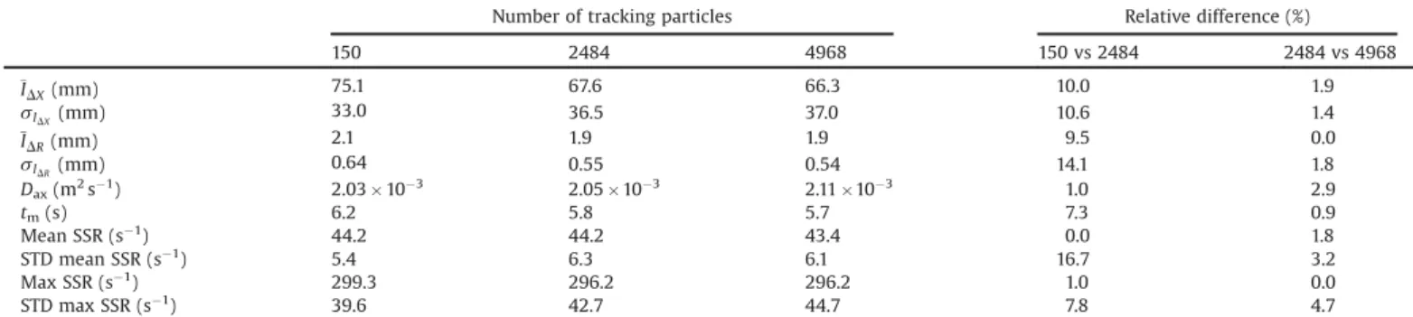
Table2showstheinfluenceofthenumberofparticlesreleased
atX0onthestatistics concerningthefluid stretching,theaxial
dispersioncoefficientand meanresidencetime, and strainrate history in the OBR with single orifice plates with oscillating conditions A=16.5mm, f=1.05Hz. The particles are releasedat X0=0.248mmanddetectedatXdetection=404mm.Itcanbeseen
that therearenon-negligible differencesin theradialandaxial stretchingvalueswhenusingonly 150particlescompared with 2484 particles; the relative difference between the values calculated for differentparticle numbers is around 10%. When comparingthevaluescalculatedusing2484and4968particles,the relativedifferenceforallquantitiesisingenerallessthan2%and therefore2484particleswhereusedforthecomparativestudy. 4.3.Influenceofreactorlengthandpositionofparticleinjection
Duetotheoscillatory(orpulsed) motionof theflow in the reactor,theaxialpositionwherethetrackingparticlesarereleased, X0, and where they are detected, Xdetection, for residence time
calculations have to be carefullychosen. Indeed if the X0 and
Xdetectionaretooclosetothetubeinletandoutlet,respectively,the
particlescanleavethecomputationaldomainduetotheoscillating flow, but cannot re-enter. To avoid this, the tube has to be sufficiently long and X0 and Xdetection must be at a sufficient
distancefromtheinletandoutlet,respectively.Furthermore,the simulation time must to belong enough toallowa maximum numberofparticlestoflowfromX0toXdetection.Itwasfoundthat
98%oftheparticlesreleasedatX0reachedXdetectionwithin50sand
thereforethesimulationtimewassetto50s.
To determinethereactorlengthandthepositions ofX0 and
Xdetection, that minimize thenumber of particles that leave the
computationaldomain,testshavebeencarriedoutforthesingle orifice baffle geometry with A=16.5mm, f=1.05Hz and a net velocity of 1.405& 10!2ms!1. Two different tube lengths
(L=310mmandL=570mm)comprising10and20baffleseach, havebeencompared.ThepositionX0andXdetectionhasbeenvaried
from64mmto272mm,i.e.approximately20–50%ofthereactor length,fromtheinlet.Xdetectionhasbeenvariedbetween85mm
and248mmfromtheoutlet,correspondingtopositionsthatare 40–83%ofthereactorlength.
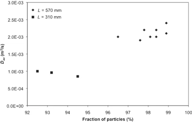
Fig.3showsthefractionoftotaltrackingparticlesdetectedat Xdetectionaftera simulation time of50sforvariedvalues of X0,
Xdetection and reactorlength.For thecase where X0/L=0.21, the
reactor length is 310mm and it can be seen that fraction of particlesmeasuredatXdetectionisnotgreaterthan95%.Indeed,it
wasobservedthatsomeparticlesleavethecomputationaldomain viatheinletandoutlet,butdonotre-enterthedomain,whichis physically incorrect. When the reactor length is increased to 570mm, which corresponds to the points where X0/L=0.30,
0.44 and 0.48, the fraction of particles detected at Xdetection is
greaterthan98%forfiveoftheeightcasestested.Itcanalsobeseen thatthefurtherX0andXdetectionarefromthetubeinletandoutlet,
respectively,thelowertheparticleloss.Asaresult,acriterionfor thechoiceoftubelengthissetsuchthatthefractionofparticles detectedatXdetectionisgreaterthan98%andX0andXdetectionare
positionedsuchthatthedistancebetweenthetwoismaximized. Based on this, the reactor length was set to 570mm and the
Table1
Influenceofthemeshsizeonradialandaxialfluidstretchingandonparametersrelatedtoresidencetimedistribution.
Baffledesign Meshsize(#cells) IDX ðmmÞ sIDX ðmmÞ IDR ðmmÞ sIDR ðmmÞ Dax(m2s!1) tm(s)
Singleorificeplate 36,000 67.6 36.5 1.87 0.55 2.05& 10!3
5.8 63,000 65.3 37.7 1.80 0.55 2.17&10!3 5.4
Singlehelicalbaffle 902,000 49.2 26.3 1.92 0.41 1.29&10!3 6.1
positions X0=248mm and Xdetection=404 mm for all of the
followingsimulations.ThefractionofparticlesdetectedatXdetection
also has a major role in the accuracy of the calculated axial dispersioncoefficientasitcanbeseeninFig.4.Indeedthevalueof theaxialdispersioncoefficientincreasesbyafactoroftwowhen the fraction of particles increases from 92–95% to 98%. The uncertaintyoftheaxialdispersioncoefficienthasbeenestimated at8%.
5. Performancecharacterisationofbafflegeometries 5.1.Radialandaxialfluidstretching
Fig. 5 showstheaverage stretchingnormalisedby thetube diameter,IDX'andIDR',ofeachfluidelementover50sasafunction of theinitialnormalisedradial positioninthe OBRwithsingle orificebaffles.Forgoodmixing,theOBRgeometryshouldpromote
stretchingin theradialdirectionbut minimize axialstretching, such that plug-flow behavior is achieved.It can be seen from
Fig.5thatingeneraltheaxialstretchingismorethan100times greater than the radial stretching for the single orifice baffle geometry.
Theaverageaxialandradialstretchingdistances(normalisedby the tube diameter)—IDX
'
and IDR'—for the different baffle geometries as a function of oscillatory Reynolds number are showninFig.6.ItcanbeseenthatIDX'increaseslinearlywiththe oscillatory Reynolds number and that mean axial stretching distance after 50s is equivalent to several tube diameters. Moreover,thestandarddeviation,representedbytheerrorbars inFig.6,issignificant(beingmorethanhalfoftheaveragevalue), whichmeansthatthestretchingdistancesarerather inhomoge-neous,asshownin Fig.5for thesingleorificebafflegeometry. Clearly,thereislittledifferenceintheaxialstretchingdistances provided by the single orifice baffles and the disc-and-donut
Table2
InfluenceofthenumberofparticlesonaveragefluidstretchingviaDXandDRandstandarddeviation,theaxialdispersioncoefficientDax,themeanresidencetimetm,andthe
time-averagedandmaximumfluidstrainratewiththeirassociatedstandarddeviations.
Numberoftrackingparticles Relativedifference(%)
150 2484 4968 150vs2484 2484vs4968
IDX(mm) 75.1 67.6 66.3 10.0 1.9
sIDX(mm) 33.0 36.5 37.0 10.6 1.4
IDR(mm) 2.1 1.9 1.9 9.5 0.0
sIDR(mm) 0.64 0.55 0.54 14.1 1.8
Dax(m2s!1) 2.03&10!3 2.05& 10!3 2.11&10!3 1.0 2.9
tm(s) 6.2 5.8 5.7 7.3 0.9 MeanSSR(s!1) 44.2 44.2 43.4 0.0 1.8 STDmeanSSR(s!1) 5.4 6.3 6.1 16.7 3.2 MaxSSR(s!1) 299.3 296.2 296.2 1.0 0.0 STDmaxSSR(s!1 ) 39.6 42.7 44.7 7.8 4.7
Fig.3. Influenceofthepositionswheretrackingparticlesarereleased(X0)anddetected(Xdetection)onthenumberofparticlesthatpassXdetectionfortheanalysis.NotethatX0/
baffles.Ontheotherhand,itisobservedforsimulationsperformed withthehelicalbladegeometriesatReO=42thatthemeanaxial
stretchingdistancedecreasesbyapproximately20–30%andthe standarddeviationisalsolower.Thelowestvaluesareobtainedfor the alternating helical baffle. Although it is not possible to generalise the improved flow performance with the helical
geometries,theseresultsdemonstratethecapacityofthemethod to detect a difference in flow performance provided by the differentequipment.
Thetrendfor radialstretchingdistances isslightly different; IDR
'
initiallyincreaseswithincreasingoscillatoryReynoldsnumber andthenremainsconstantfromapproximatelyReO=40.Theradial
Fig.4.Influenceofthefractionoftrackingparticlesrecordedontheaxialdispersioncoefficient.
Fig.5.Axial(a)andradial(b)stretchingoffluidelementsnormalizedbythetubediameterasafunctionoftheirinitialnormalisedradialpositionforthesingleorificebaffle geometrywithanoscillationamplitudeof16.5mmandafrequencyof1.05Hz.
stretchingdistancesarealsomuchsmallerthantheaxialdistances, typicallyrangingbetween5%and15%ofthetubediameterandthe standard deviationsarealsosmaller.Apartfromthealternating helical blade,thebaffle geometryhaslittle effectontheradial stretchingdistances.FortheoscillatoryReynoldsnumbertested, the alternating helical blade however enables the mean axial stretchingdistancetobeincreasedbyafactoroftwo,compared withtheothergeometries.
5.2.Residencetimedistributionandaxialdispersioncoefficient The residence time distribution E(t) of an ideal plug-flow reactorisaninfinitelyhighpeakwithzerowidth.Thedispersion model,whichinvolvesanaxialdispersioncoefficientDax,allows
thenon-idealbehaviorofthereactortoberepresented.Daxcanbe
calculatedfromtheresidencetimedistribution,whichhasafinite widthandheight.TheresidencetimedistributionsE(t)obtained
Fig.6.Mean(a)axialand(b)radialstretching(normalisedbytubediameter)asafunctionoftheoscillatoryReynoldsnumberandfordifferentbafflegeometries.Theerror barsrepresentthenormalisedstandarddeviation.
withthesingleorificebafflesfordifferentoscillatoryamplitudes andfrequenciesaregiveninFig.7.
ItcanbeseenthatthemaximumvalueofE(t)decreaseswith increasingoscillationamplitudeandincreasingfrequency.Among thedifferentoperatingconditions tested,thehighest peaksare obtainedforsmalloscillationamplitudesA=5mmand10mmat f=0.635Hz(Fig.7(a,b)).Howeverthesepeaksareappearingmuch earlierthanthetheoreticalspace-timevalue,therebysuggesting
short-circuiting.Formostoftheotheroscillationconditionsthe peakisveryloworeveninexistent,indicatingthatthereisalarge spreadin theresidencetime distribution,therebyshowingthat plugflowisnotachieved.
ThePécletnumbersandthenormalisedmeanresidencetimes atdifferentoscillatoryReynoldsnumbersforafixednetflowrate andreactorlengtharepresentedinFig.8.Itcanbeseenthatinthe studied range, the Péclet numbers—and therefore the axial
dispersion coefficients—vary very little with the oscillatory Reynolds number and hence with oscillation amplitude. For a fixedfrequencyof1.05Hz,thesingleorificebaffleclearlyshowsthe lowestvaluesofthePécletnumber,whichareclosetoone,whilst thecentraldiscinthedisc-and-donutconfigurationclearlylimits someaxialdispersion,byslightlyincreasingthePécletnumber.At Reo=42,itisobservedthatsignificantlyhigherPécletnumbersare
obtainedforthesingleandalternatinghelicalbaffles.Whenhigher
oscillatingfrequencies(e.g.1.273Hzand1.606Hz)areusedwith the singleorifice and the disc-and-donut baffles, however, the Péclet numbers are greater (and therefore theaxial dispersion coefficientsarelower)thatthoseobtainedatthesameoscillatory Reynoldsnumberwithf=1.05Hz. Thisissurprisingconsidering the shape of the RTD curves for single orifice baffle at these frequencies(Fig.7(g)and(h))thatshowsignificantdistribution, meaningtheflowisverydifferentfromplug-flowwherethetracer
would exit at a single instant in time. The associated Péclet numbersarealsoverylow!between1.1and2.2.Indeed,theaxial dispersion model for plug flow reactors is valid for Péclet numbers>10[18] and thissuggeststhatthemodelmaynotbe appropriateforhighfrequencies.Fig.8(b)showsthatthemean residencetimesareapproximatelyhalfthetheoreticalresidence
time (or space time), which implies the presence of stagnant backwatersandreducedeffectivereactorvolume[18].Indeed,this canbeexplainedwiththevelocityfieldsshownFigs.4–8inPartIof thispaperthat clearlyshoweitherclosedrecirculationloopsor zones of low velocity closetothe vessel wall, contrasted with significantlyfast-flowingfluidinthecentreofthetube.
Fig.9showstheeffectofthenetReynoldsnumber(calculated for fixed oscillationconditions (A=16.5mmand f=1.05Hz) and reactorlengthL)onthePécletnumberinthesingleorificebaffled reactor. Althoughthevaluesare low,thePécletnumber clearly decreaseswithincreasingReOandthereforeflowrate.Indeed,the
axial dispersioncoefficientincreasessignificantlywiththeflow rateinthisrangeofReO.Howeverwithafurtherincreaseinflow
rate,onewouldexpectadecreaseinthedispersioncoefficientand consequentlyanincreaseinthePécletnumberastheflowregime becomesturbulent.
Fig.10presentstheeffectofreactorlengthonaxialdispersion andmeanresidencetimeforconstantReOandRenetinthesingle
orificereactor.Itcanbeseenthatatfixedoperatingconditionsthe axialdiffusioncoefficientremainsmoreorlessconstantalongthe reactorwithavaluethatisapproximatelysixordersofmagnitude greater thanthemoleculardiffusioncoefficientforliquids.This means that for set operating conditions, there is a linear relationshipbetweenPécletnumberand thereactorlengthand therefore plug-flowbehaviorcanbeachievedbyincreasingthe length of the reactor.For example, in thesingle orificebaffled reactor with theoperating conditions given in Fig.10 a Péclet number equal to 40, which allows for reasonable plug flow conditions,canbeobtainedwithareactorlengthofapproximately 6m.Indeed,thetendencytomovetowardplug-flowbehavioris alsoshownbycomparisonofthemeanresidencetime,tm,withthe
net space time,
t
net, for increasing reactorlength as shown inFig.10(b).Theresultsshowthatthemeanresidencetimefirstly deviatesfrom
t
netwithincreasingreactorlengthbeforeconverg-ingtothetheoreticalvalue.Forshortreactorlengthsthedifference betweentmand
t
netisduetothehighvelocitygradientscreatedbetweenthecentreofthetubeandbehindtheorificebafflesclose tothetubewall. Asthetubeismadelonger,thedifferentfluid elementshavethetimetosamplethevariationsinvelocityand
eventuallyallfluidelementshaveexperiencedthesameflowon average,therebyleadingtotm=
t
net.5.3.Shearstrainratehistory
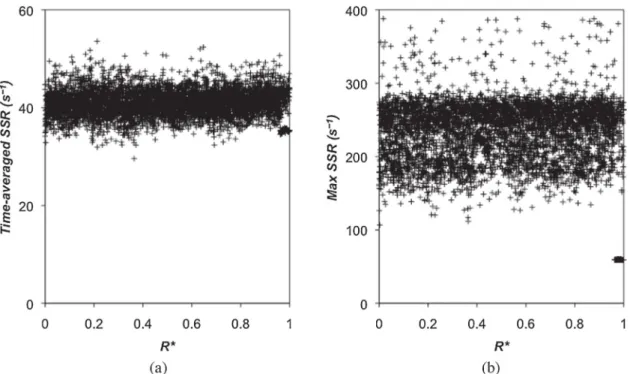
Due to the different baffle geometries and varying velocity gradients, fluid elements can experience significantly different shearstrainratesduringtheirtimeinthereactor.Toinvestigatethe differencesinstrainrates,thetime-averagedstrainrate,themean strainrateandthemaximumstrainrateexperiencedbythetracer particles have been calculated. Fig. 11 shows the strain rate experiencedbythefluiddependingontheinitialradialpositionof thefluidelementwiththealternatinghelicalbaffles.Itcanbeseen inFig.11(a)thatgloballyover timethedifferentfluid elements experiencemoreorless thesame strainrate, whichis approxi-mately40(5s!1.Fig.11(b)showsthatthereisgreaterspreadin
the maximum strain rates, however the majority of the fluid experiencesmaximumstrainratesbetween150s!1and250s!1,
whicharerelativelyhighvalues.Thismeansthatinthisgeometry, theensembleoffluidexperiencesthesameshearratesandthat thereare nomajor hydrodynamicpassages wherefluid experi-encesgloballyexcessiveorweakdeformation.Thistypeofanalysis may be particularly useful when assessing the capacity of particularbafflegeometriestoinduceoravoidhighstrainrates and the homogeneity for shear sensitive applications, such as dropletbreak-uporcellculture.
Fig.12showstheinfluenceoftheoscillationconditions,viaReO,
and the baffle design on the global mean and the average maximum strain rates. The error bars indicate the standard deviation of the strain rate experienced by the ensemble of particles at each operating condition. It can be seen that the maximumshearstrainrateisapproximatelysixtimestheaverage valueandthattheshearstrainratevaluesincreaselinearlywith
Fig.9.ThePécletnumberasafunctionofthenetReynoldsnumberforfixedoscillationconditionsA=16.5mmandf=1.05HzandreactorlengthLinthesingleorificebaffled reactor.
theproductA.f.Thismeansthathighoscillationsconditionsmay be preferred for droplet breakup or solid de-agglomeration applications; however it is important to remember that axial stretchingalsoincreaseswithincreasingoscillationconditionssoa bestcompromisemayneedtobefound.Anindicationoftheeffect ofthedifferentgeometriescanalsobeseenatReo=42.The
disc-and-donutbafflesareshowntogeneratethehighestshearstrain
ratesin thereactor,whilstthevalues fortheotherdesignsare lower and vary only slightly. It is interesting to note that the standarddeviationislowerforthehelicalbaffledesigns,which meanstherearesmallerdifferencesofstrainrateexperiencedby theparticlesforthesegeometries.Ithasalsobeenfoundthatfor fixed oscillationconditions andvarying flowrate, i.e.Renet, the
meanshearstrainrateisalmostconstantandthemaximumstrain
Fig.10.Effectofreactorlengthon(a)theaxialdiffusioncoefficientand(b)themeanresidencetimeforthesingleorificebafflegeometrywithA=16.5mmandf=1.05Hz (ReO=43)andRenet=5.5.
rateincreasesonlyveryslightlywithincreasingflowrate.Indeed, shear strain in the reactor is controlled principally by the oscillatingconditions.
6. Conclusions
Inthisworkthreeanalysismethodsforcharacterisingtheflow generated in oscillatory baffled reactors have been developed. These methodsanalyseaxialand radialstretching(andmixing) capacity,shearstrainratehistoryandresidencetimedistribution usingdataobtainedusingCFD.Axialandradialstretchingisuseful to evaluate spatial mixing and the presence of chaotic flow, if required;shearstrainrateisusefulforapplicationsthatare shear-dependent,suchasdropletbreakup,de-agglomeration, applica-tionsinvolvingbiologicalcultures;residencetimedistributionis usefulwhenchemicalreactionsarebeingperformed.Inageneral manner, these methods have then been used in this paper to comparetheperformanceoftheOBRequippedwithnovelbaffle designsandoperatingunderdifferentflowconditions.
Ithasbeenshownthattheoscillatingconditions,i.e.amplitude andfrequency,haveastrongeffectoncertainmeasures,whereas the flow rate has very little influence. Axial stretching and dispersion,aswellshearstrainrateincreasewhentheproductA.f increases.However,radialstretchingandmixingvariesverylittle withthisparameter.ThePécletnumberalsovariesverylittlewith A.f (when f is constant) but is affected by higher oscillation frequencies.
Comparisonofthedifferentbafflegeometrieswiththedifferent performancemeasuresatasinglevalueofReodemonstratesthe
capacity of themeasures todifferentiatethecapabilitiesof the differentdesigns.Atthisoperatingpointit isobservedthatthe novelhelicaltypebaffles,inparticularthesingleandalternating helical blades, provide slightly less axial stretching and Péclet
numbersthatareapproximately80%greaterthanthosegenerated bythesingleorificeanddisc-and-donutbaffles.Thedoublehelical bafflealsoenablesradialstretchingandmixingby80%compared withtheothergeometries.Interestingly,thecentraldiscof the disc-anddonut-designdoesnotimproveradialmixingordecrease axial dispersion significantly compared with the single orifice baffle.Thesharpedges(perpendiculartotheflow)ofthe disc-and-donutdesigndohoweverenableshearstrainratesthatarearound 30% greater than those achieved with the other geometries. Althoughnofirmconclusionscanbemadeatthisstageregarding thegeneralperformanceofthehelicaldesignsforawiderrangeof operating conditions, the characterisation methods provide indicationsofthecharacteristicsthatcanbeimprovedwitheach geometry.
ConsideringtheresultsonthepressuredroppresentedinPartI, it appears that the disc-and-donut design induces excessive pressure loss compared with the other geometries without providing a significant gain in performance in terms of radial andaxialstretchingand residencetimedistribution.Thehelical bladedesignshoweverprovideimprovedperformanceintermsof radialmixingandresidencetimedistributioncomparedwiththe traditional single orifice baffles for only a small increase in operatingcosts.Indeedthedisc-and-donut bafflesappear tobe particularlysuitedtomultiphaseflowapplicationswhereinterface generation is required by high shear strain rate. In order to concludewhethertheadditionaloperatingcostofthe disc-and-donutdesignsforgeneratingdispersionsisworthwhilecompared with thehelical blade baffles, further experimental studies on dropletgenerationandsizewouldberequired.
Theensembleof theseresultsclearly suggestthatthebaffle geometryof theOBR shouldbechosen in consideration of the processobjectives for bestoperating performance and that the measurement parameter(s) used tocharacterise reactor perfor-manceshouldalsobechosendependingontheprocessobjective.
Fig.11.(a)time-averagedstrainrateand(b)maximumstrainrateexperiencedbyfluidelementsasafunctionoftheirinitialnormalisedradialpositionforthealternating helicalbafflegeometrywithanoscillationamplitudeof16.5mmandafrequencyof1.05Hz.
Acknowledgements
ThisworkwaspartoftheAGRIBTPprojectonbio-productsfor buildingandpublicworksfundedbytheEuropeanUnion,région Midi-Pyrénées and the French Government. D.F.F. gratefully acknowledgesfundingfromINPToulouse.
References
[1]A.Mazubert,D.F.Fletcher,M.Poux,J.Aubin,Hydrodynamicsandmixingin continuousoscillatoryflowreactors—PartI:effectofbafflegeometry,Chem. Eng.Proc.PI(2015)Submitted.
[2]X.Ni,H.Jian,A.W.Fitch,Computationalfluiddynamicmodellingofflow patternsinanoscillatorybaffledcolumn,Chem.Eng.Sci.57(2002)2849– 2862.
[3]X.Ni,H.Jian,A.W.Fitch,Evaluationofturbulentintegrallengthscaleinan oscillatorybaffledcolumnusinglargeeddysimulationanddigitalparticle imagevelocimetry,Trans.IChemE81(A)(2003)842–853.
[4]M.Zheng,J.Li,M.R.Mackley,J.Tao,Thedevelopmentofasymmetryfor oscillatoryflowwithinatubecontainingsharpedgeperiodicbaffles,Phys. Fluids114101(2007).
[5]A.A.Hamzah,N.Hasan,M.S.Takriff,S.K.Kamarudin,J.Abdullah,I.M.Tan,W.K. Sern,Effectofoscillationamplitudeonvelocitydistributionsinanoscillatory baffledcolumn(OBC),Chem.Eng.Res.Des.90(2012)1038–1044. [6]X.Ni,J.A.Cosgrove,A.D.Arnott,C.A.Greated,R.H.Cumming,Onthe
measurementofstrainrateinanoscillatorybaffledcolumnusingparticle imagevelocimetry,Chem.Eng.Sci.55(2000)3195–3208.
[7]P.Stonestreet,P.M.J.VanderVeeken,Theeffectsofoscillatoryflowandbulk flowcomponentsonresidencetimedistributioninbaffledtubereactors, Trans.IChemE77(A)(1999)671–684.
[8]M.Palma,R.Giudici,Analysisofaxialdispersioninanoscillatoryflow continuousreactor,Chem.Eng.J.94(2003)189–198.
[9]K.B.Smith,M.R.Mackley,Anexperimentalinvestigationintothescale-upof oscillatoryflowmixinginbaffledtubes,Chem.Eng.Res.Des.84(2006)1001– 1011.
[10]A.N.Phan,A.P.Harvey,Developmentandevaluationofnoveldesignsof continuousmesoscaleoscillatorybaffledreactors,Chem.Eng.J.159(2010) 212–219.
[11]A.N.Phan,A.P.Harvey,Effectofgeometricalparametersonfluidmixingin novelmesoscaleoscillatoryhelicalbaffleddesigns,Chem.Eng.J.169(2011) 339–347.
[12] A.N.Phan,A.P.Harvey,Characterisationofmesoscaleoscillatoryhelicalbaffled reactor!Experimentalapproach,Chem.Eng.J.180(2012)229–236. [13]A.N.Phan,A.P.Harvey,J.Lavender,Characterisationoffluidmixinginnovel
designsofmesoscaleoscillatorybaffledreactorsoperatingatlowflowrates (0.3–0.6ml/min),Chem.Eng.Proc.50(2011)254–263.
[14]X.Nogueira,B.J.Taylor,H.Gomez,I.Colominas,M.R.Mackley,Experimental andcomputationalmodelingofoscillatoryflowwithinabaffledtube containingperiodic-tri-orificebafflegeometries,Comp.Chem.Eng.49(2013) 1–17.
[15]M.Manninen,E.Gorshkova,K.Immonen,X.W.Ni,Evaluationofaxial dispersionandmixingperformanceinoscillatorybaffledreactorsusingCFD,J. Chem.Tech.Biotech.88(2013)553–562.
[16]H.S.Fogler,ElementsofChemicalReactionEngineering,2nded.,PTRPrentice Hall,EnglewoodCliffsNJ,1992.
[17]J.Aubin,L.Prat,C.Xuereb,C.Gourdon,Effectofmicrochannelaspectratioon residencetimedistributionsandtheaxialdispersioncoefficient,Chem.Eng. Proc.PI48(1)(2009)554–559.