Tailoring Orbital Angular Momentum of Light in the Visible Domain with Metallic Metasurfaces
Texte intégral
Figure
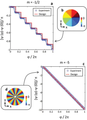
![Figure 1. SEM images of a–c) fundamental [ = − 1/ 2] and d–f) high-order [m = − 5] metasur- metasur-faces with thickness h = 300 m, diameter Dμ = 100 m, grating period μ Λ = 500 nm, and slit width W = 160 nm](https://thumb-eu.123doks.com/thumbv2/123doknet/14531598.533737/3.891.75.542.107.581/figure-images-fundamental-metasur-metasur-thickness-diameter-grating.webp)

Documents relatifs
Seasonal and diurnal variations of nitrate in the gas and aerosol phase were observed with more than 50% of the total nitrate in the gas phase during August and more than 80% of
In Chapter 5 we develop a continuous variable inequality using bounded spectrum oper- ators and propose an experimental setup to measure the inequality using correlations on
Lines 1, 2 and 3: respectively 0, 1 and 2 ℏ/photon; 1=experimental, 2=theoretical; columns 1 and 2: beam intensity; columns 3 and 4: intensity in the focal plane of the
La répartition des germes dans notre étude reste à peu près la même pour toutes les tranches d’âge, à l’exception de Streptococcus B qu’on retrouve
Only eight absorption peaks are expected in the Mossbauer spectrum for an I = 5; to I = 4 transition in such a longitudinal field, but, since the z-component
In particular we want to know when the following conjec- ture made by Clark [2005] is an optimal solution to this mixed optimal control problem: if the harvesting capacity is
The inspection (path) planning is the problem of finding an inspection trajectory that is informative enough to gather data (such as sonar and LiDAR data) from different
A doubly-rippled surface with small, constant radius of curvature undulations is shown to yield a factor of two increases in the rate of vapor space condensation
