HAL Id: inria-00337568
https://hal.inria.fr/inria-00337568
Submitted on 7 Nov 2008
HAL is a multi-disciplinary open access
archive for the deposit and dissemination of
sci-entific research documents, whether they are
pub-L’archive ouverte pluridisciplinaire HAL, est
destinée au dépôt et à la diffusion de documents
scientifiques de niveau recherche, publiés ou non,
Frédéric Beck, Olivier Festor, Radu State
To cite this version:
Frédéric Beck, Olivier Festor, Radu State. High Security Laboratory - Network Telescope. [Technical
Report] 2008. �inria-00337568�
Th `eme COM
High Security Laboratory - Network Telescope
Fr´ed´eric Beck, Olivier Festor and Radu State
N° 9999
Fr´
ed´
eric Beck, Olivier Festor and Radu State
Th`eme COM — Syst`emes communicants
Projet MADYNES
Rapport technique n
°9999 — March 2007 — 219 pages
Abstract:
T´
el´
escope R´
eseau
R´
esum´
e :
Contents
1 Introduction
6
2 LHSI
7
2.1
Requirements . . . .
7
2.2
Network Telescope . . . .
7
2.2.1
Objective and Functionalities . . . .
7
2.2.2
Telescope Architecture . . . .
8
3 Physical Infrastructure
10
3.1
Material . . . 10
3.1.1
Specifications . . . 10
3.1.2
Characteristics . . . 14
3.2
Physical Implantation . . . 15
3.2.1
Servers Room . . . 16
3.2.2
Racks and Weight Repartition . . . 17
4 Network Infrastructure
18
4.1
Network DSL Connections . . . 18
4.2
Cabling . . . 19
4.3
Logical Infrastructures . . . 23
4.3.1
Private Network . . . 24
4.3.2
VLANs . . . 25
4.3.3
Firewalling . . . 26
5 Hardware and Operating Systems
32
5.1
PowerEdge 2950 storage and PowerVault MD1000 . . . 32
5.1.1
PE2950 . . . 32
5.1.2
MD1000 . . . 34
5.2
PowerEdge 2950 collect and anaslysis . . . 36
5.3
KVM 2161DS-2 Switch . . . 36
5.3.1
Network . . . 36
5.3.2
Access and Configuration . . . 37
6 Softwares
38
6.1
Logging Server . . . 38
6.1.1
Overview . . . 38
6.1.2
SurfIDS Logserver . . . 39
6.1.3
Mail reporting . . . 48
6.1.4
RRD scripts . . . 50
6.1.5
Google Map . . . 50
6.1.6
Antivirus analysis . . . 52
6.2
Low Interaction Honeypots . . . 55
6.2.1
Nepenthes . . . 55
6.2.2
p0f-db . . . 63
6.2.3
Argos . . . 65
6.3
Virtualization . . . 76
6.3.1
Xen . . . 76
6.3.2
Qemu . . . 82
6.4
Netflow . . . 82
6.4.1
Probe . . . 82
6.4.2
Collector . . . 83
6.4.3
WEB Interface . . . 83
6.5
Backup . . . 86
6.5.1
Database . . . 86
6.5.2
Daily backup . . . 87
6.5.3
Manual Save . . . 88
7 Deployment
90
7.1
Sensors Deployed . . . 90
7.2
Results . . . 90
7.2.1
Attacks and Binaries Downloaded . . . 90
7.2.2
Antivirus Scanning . . . 92
7.2.3
Network Traces . . . 92
7.2.4
Sandboxing . . . 92
8 Maintenance
95
8.1
Starting the servers . . . 95
8.2
Shutting down the platform . . . 95
8.3
Daily status check . . . 96
8.4
Communication . . . 97
9 Conclusion and Future Work
98
List of Figures
1
Architecture of the Network Telescope . . . .
9
2
First Rack Specifications . . . 15
3
Second Rack Specifications . . . 16
4
Physical Deployment in the Server Room . . . 17
5
Video Export . . . 18
6
Network Infrastructure (Collecting Environment) . . . 20
7
Network Infrastructure (Analysis environment) . . . 21
9
VLANs Deployment . . . 26
10
Transparent Firewall . . . 28
11
Firewall Rules . . . 29
12
Surfnet IDS Architecture
. . . 38
13
Daily Mail report . . . 49
14
Network and Memory Usage Graphs . . . 51
15
Attackers Geolocalisation . . . 52
16
Binaries Scanning Results . . . 55
17
Creating an Argos Image Template . . . 75
18
NfSen - Packets per second . . . 86
19
Evolution of the Attacks . . . 91
20
Network Traces . . . 93
1
Introduction
The 2nd November of 1988, the worm Morris attacked successfully about 6 000 computers
connected to the Internet. 15 years later, the 25th of January 2003 at 5:30 UTC, the Slammer
worm paralyzed the Internet by exploiting an Operating System vulnerability discovered 6
months earlier. In no more than 10 minutes, this worm duplicated itself and infected 90%
of the vulnerable computers. Nowadays, a well programed worm could possibly freeze the
Internet in only a few seconds (flashworms). Reality meets fiction, as the scenario of the
Terminator 3 movie, where the Skynet system takes control of the defense networks by
injecting a virus, is technically realistic today, our dependency to computers being each day
more important and the systems interconnection being beyond human control.
Viruses, malwares and worms spreading over the Internet, cause billions euros of
dam-ages to our economy. They are a real threat for our society. Actual infrastructures, like
communications or energy transport, highly depend on computer networks. A bug,
espe-cially due toe a malicious act, can keep us from benefiting from them. A viral attack, such
as Slammer, forbids the access to the resources spreaded all over the Internet. For example,
the supervision network of the nuclear power plant of Besse-Davis in Ohio was paralyzed for
almost 24 hours after Slammer’s attack. Other kind of attacks can change the aspect of a
website, modify some informations, steal private data, or even worse, use our own systems
to commit crimes, incriminating ourselves behind our awareness. If such an attack is not
detected, a person using the altered information may take a false decision. The dramatic
consequences that can result from that are easily understandable.
These threats examples show the trend reversal we are facing. After the big pirates and
hackers invasions of the 2000s, malicious codes are keeping low profile to succeed in their
wrongdoings, acting as spies in our systems. Viruses are weapons, and depending on who
is controlling them, they can be deadly weapons. Thereby, the french newspaper Le Monde
revealed the 5th of October 2007 that several countries, including the USA, Germany, France
and New-Zealand, had announced that they suffered cyber-attacks coming from China.
While attacks are widespread, network data related to them is rarely available to academies
for investigation. In this context, the MADYNES team, which develops research activities
on security management, decided to build an infrastructure capable of collecting the
nec-essary data to enable analysis and modeling of malicious systems from a network point of
view. This infrastructure is now part of the LORIA High Security Laboratory.
2
LHSI
In this section we will present and motivate the High Security Laboratory (LHSI).
2.1
Requirements
A High Security Laboratory (LHSI) should permit to perform certain experiments under a
legal umbrella, with the possibility to publish results and data. The experiments
consid-ered are the deployment of attack and defense systems against malicious programs (viruses,
malwares...), the usage of viral technologies to develop new technologies, vulnerabilities
detection, security audit, and systems certification.
Indeed, any design or deployment error can lead to an uncontrolled propagation,
theo-retically over the whole Internet, with important legal and operational consequences. We
are aware that flashworms like viral propagation methods could paralyze the Internet in less
than 10 seconds. therefore, the safety and security issues of the emissioned laboratory are
critical.
The High Security Lab is composed of two distinct projects, closely related:
A network telescope, which role is to collect malwares together with network traces in
order to analyze them;
Pro-active defense against known malwares.
In this report, we focus on the first sub-project, namely the network telescope.
2.2
Network Telescope
2.2.1
Objective and Functionalities
The objective of the telescope is the design, deployment and operation of a network telescope.
The primary function of a network telescope is the capture, analysis and distribution of
malware data, including both binaries and network related traces. In our project, the
telescope is an epidemiological sensor for the detection of new viruses or malwares, and
estimate the degree of infection of known threats. Therefore, the telescope will ensure the
following three functionalities:
1. Large scale malicious code capture. To do so, we will use a platform that emulates
vulnerabilities and captures the malwares who try to exploit these vulnerabilities. this
emulation is perfectly controlled, as the malicious code is not able to gain control of
the system. Such an environment can be based on a low-interaction Honeypot (such
as Nepenthes). The captured code is analyzed to identify if it is a known malware or
not. The capture of an unknown malicious code is essential for pro-active defenses;
2. Collect network traces. The second set of informations we are interested in is the
network traffic of these malwares. This gives us information about the source of the
attack, its behavior, the distribution and geographical repartition of infections. These
data are complementary with the malicious code, as it gives information on their
net-work behavior, and more precisely the mechanisms the malwares use to spread;
3. ”In vitro” and ”in vito” analysis of the malicious code. Malwares are still mysterious
about how they deploy and spread themselves, their behavior and their interactions
and communications with other malwares. We need to analyze both ”in vitro” and
”in vito” the collected malwares, and evaluate the vaccination and defense solutions
against them. This actions is closely related with the pro-active defense sub-project
outside the scope of MADYNES.
2.2.2
Telescope Architecture
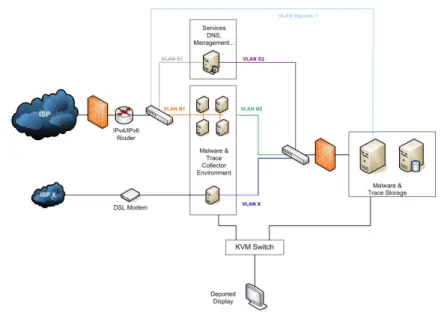
As shown in figure 1, the network telescope is composed of 5 different components:
An environment collecting malwares and network traces;
An environment storing these malwares and traces;
An environment to deal with the collected data. Each malware will be analyzed by
known anti-virus and kept in a dedicated database. The traces will be anonymized
and linked to the malwares they belong to via timestamps;
An ”in-vitro” analysis environment, which will make possible to deploy the malwares
in a large scale platform and study its behavior. This environment will be physically
separated and isolated, in order to permit a safe emulation of the malware;
A dissemination infrastructure for the scientific community in order for them to access
a subset of the collected data (traces, and under certain conditions the code itself).
This architecture has to be deployed by using Open Source softwares, and has to rely on
virtualization in order to host several sensors and collectors on each server.
3
Physical Infrastructure
In this chapter, we present more precisely the physical infrastructure deployed. We present
the equipment and its physical implementation.
3.1
Material
In this section, we specify the equipment we chose and motivate our choices.
3.1.1
Specifications
Servers
For this kind of experiments, the CPU and its frequency was not the main factor for us. We
were more concerned about heat production and electrical consumption. Actually, to run
honeypots, we do not need much CPU or RAM. We estimated that 512 MB of RAM and
two Virtual Machines (VM) per CPU core is a reasonable architecture. Thus, we opted for
quad-core CPUs and 8 GB of RAM. In order to limit the heating and power consumption
of our servers, we chose to select components with the label Energy Smart.
Our first choice was to pick Dell PowerEdge 1950 (PE1950) servers, because they only use
one unit in racks. However, as we wanted at least 500 GB of hard disk, and as the PE 1950
can only accept up to two 2.5¨
disk (up to 2x146 GB), we had to take Dell PowerEdge 2950
(PE2950) server, which uses two rack units, but can embed up to 8 disks. We filled it with
six 146GB SAS 10K rpm hard drives. Moreover, these servers come with a Perc 5/i SAS
RAID card and two network interfaces. For our experimentations, and in order to balance
the network load between the different VMs, we wanted more than 2 network interfaces.
Thus, we added a network card with two Gigabit network interfaces. To ensure reliability,
we took a redundant power supply. Finally, we chose 5 years of on site warranty (Day+1),
and put a floppy and DVD drive in each server, to ease the installation and diagnostic in
case of problems.
In our market with Dell, these servers were identified in the 4th Category as the second
configuration. The following table details the servers specification. The prices are those paid.
Designation
Quantity
Price
PowerEdge 2950 with redundant power supply
1
1 800
¿Bi processor Intel Xeon L5320 LV (1.86GHz)
quad core 2x4Mo Energy Smart
1
410
¿8GB FB 667MHz (4x2GB dual rank DIMMs) Energy Smart
No operating System
Broadcom 2 Port TCP/IP Offload Engine (TOE) Not enabled
3.5” 1.44MB Floppy Drive
16x IDE CD/DVD
1
3,30
¿Riser with PCI Express support (2xPCIe x8 slots; 1xPCIe x4 slot)
PE2950 Rapid/Versa Rails
Perc E/i integrated SAS RAID x6 backplane
2x146GB, SAS, 10K, 2.5inch, Internal
1
88
¿Additional Intel Pro 1000PT 2 Ports Gigabit
1
63,40
¿Additional 146GB, SAS, 10K, 2.5inch, Internal
4
726.40
¿Total
3 091,10
¿5 years on site (day+1) warranty
217,50
¿Total with warranty
3 308,60
¿Total with taxes
3 957.09
¿We ordered 13 such servers, which are dispatched as follows:
7 servers for the collect environment;
1 server for the storage environment;
5 servers for the analysis and test environment.
In order to store all the collected malwares and traces, we need a storage unit. We
estimated that in a first phase of the project, a storage capacity of 3 to 4 To would be
sufficient. We will adapt this capacity in the second phase of the project, and add a second
storage unit for redundancy and data durability.
To meet these requirements, we chose a Dell PowerVault MD1000 unit, with the following
specifications.
Designation
Quantity
Price
PowerVault MD 1000 SAS/SATA
1
2 100
¿3x 500 GB SATA II 7,2K rpm, 3,5 inch Internal
Perc 5/e Card
Rapid Rails
External SAS connector cable 1m
Additional 500 GB SATA II 7,2K rpm, 3,5 inch
6
1 140
¿Total
3 240
¿5 years on site (day+1) warranty
298
¿Total with warranty
3 538
¿Total with taxes
4231,44
¿Initially, we only bought one unit. It uses 3 rack units. The Perc 5/e card that comes
with the MD1000 is meant to be put in the PE2950 server which will operate it. One of the
6 500 GB hard drives is kept back as spare disk in case of failure of one of the 7 others. We
plan to configure the MD1000 to use RAID 5, which gives us 3 To of storage capacity.
Network Components
In order to create the different networks and environments, we need several network
com-ponents. The routers we need to connect to the network will be provided by the ISPs.
We need:
one simple 24 ports switch at the output from the border router;
one 24 ports switch with VLAN routing capabilities between the different collecting
environment and the storage environment;
one firewall to protect the storage environment;
one simple 24 ports switch to connect the storage environment and the analysis
envi-ronment.
We chose Cisco equipment. The following table describes the equipment we bought with
our provider:
Designation
Quantity
Price
Catalyst 2960 24 10/100 + 2 1000BT LAN Base Image
2
1 036
¿MAJ soft + Exchange NBD / 3 years
2
60
¿Catalyst 3560 24 10/100/1000T + 4 SFP + IPB Image
1
1 916
¿MAJ soft + Exchange NBD / 3 years
1
278
¿ASA 5510 Security Plus Appl with SW, HA, 2GE + 3FE, 3 DES/AES
1
1 836
¿MAJ soft + Exchange NBD / 3 years
1
826
¿2m CAT6 RJ45
25
48,50
¿3m CAT6 RJ45
25
64,25
¿10m CAT6 RJ45
2
13,88
¿Total without taxes
6 078,63
¿Total with taxes
7 270,04
¿This command includes the network RJ45 cables that we needed to connect all the servers
and network components. The Catalyst 3560 switch contains 4 optical connectors, which
can be used to connect an optical fiber in case of relocation of the platform.
Racks and Related Components
In order to set up the platform, some racks and associated parts were necessary.
To begin with, as we will not operate the platform directly in the server room, we need
to export the display. Originally, for security issues, to avoid any virus spreading from the
telescope, we thought of using an analog export. But with such a solution, we are limited
to 8 meters (theoretically 15 meters, but Dell is not selling any cable longer than 8 meters,
as the quality with longer cables is not warranted). Therefore, we decided to go for a digital
export via Ethernet on a dedicated RJ45 cable. This solution makes possible to export as
far as RJ45 cables permit it, without the problem of signal degradation being as marked as
with analog export. It also makes possible to have two sessions at the same time to operate
the platform, which can be useful if several persons want to work on it at the same time.
Concerning security issues, the data exported is only video information. The video signal
coming out from the analog ouput from the servers is transcoded by the KVM switch and
exported via Ethernet. There is no possible way any virus might spread over this RJ45 link,
as the video switch act as a physical barrier. To operate the platform via this digital export,
the client is mandatory a Windows machine with the proprietary client provided with the
video switch.
If the platform is moved too far for an RJ45 cable to transport the video data, we will
be able to use the fiber ports on the Cisco Catalyst 3560 switch to perform the export on a
longer distance.
To meet these requirements and respect the public markets defined at INRIA, we chose
the KVM Digital switch 2161DS-2. It makes possible to export the display of 16 servers
over IP. Even if we do not have at the moment 16 servers in our platform, we ordered 16
cables to connect the servers to the switch, to avoid any trouble for further extensions.
The servers are meant to be integrated in racks. We had the choice between 42 and 24
units racks. Considering the number of devices we have to install, we chose to take two
24 units racks instead of one 42 units. This choice was also motivated by the fact that
taking two racks permits to dish the weight out on the floor and not have all the weight
concentrated in 1 m
2. Having two racks also gives us the opportunity to physically separate
the collecting and storing/analysis environments, with minimum amount of cables going
from one rack to the other one. Finally, as it is considered to move the platform for the
second phase of the project, having two racks makes this move easier, as a 24 units rack is
shorter (1,20 meters) and lighter than a 42 units rack (2 meters tall).
In order to connect all the devices to AC power supplies, we put Power Distribution
Units (PDU) in the racks. As we have Energy Smart servers with redundant power supplies,
we need low tension PDUs. the ones available in the market have 13 ports. Thus we took
2 for each rack for a total of four Low Tension PDU 13 ports 16A 230V. The PDUs come
with a tri-phased connector to power supplies. As this kind of plug was not available in our
building, we had to modify them so that they fit in our electrical infrastructure.
The following table shows the summary of this material:
Designation
Quantity
Price
KVM Digital switch 2161DS-2
1
1 974,40
¿Cable interface USB
16
691,20
¿24 units rack
2
1340
¿Low Tension PDU 13 ports 16A 230V
4
243,60
¿Total without taxes
4249,20
¿Total with taxes
5 082,04
¿Total
All these components have a total price of 68 025,70
¿including taxes.
3.1.2
Characteristics
In this section, we will present the physical characteristics of each components as specified
in their own documentation.
The size occupied by the equipment is delimited by the size of the 24 units racks. Such
a rack has a width of 61cm, a depth of 100cm and a height of 120cm. That gives two times
a floor surface of 0,6m
2. The weigh of such an empty rack is theoretically 108,9 Kg, even if
it seems lighter in reality.
In the first rack, we have:
7 PE2950 servers
1 KVM switch
1 Cisco Catalyst 3560 switch
2 PDUs
Figure 2 shows the characteristics of this rack.
Figure 2: First Rack Specifications
In the second rack, we have:
6 PE 2950 servers
1 MD1000 storage unit
1 Cisco Catalyst 2960 switch
2 PDUs
Figure 3 shows the characteristics of this rack.
This gives us one rack with 327,63 Kg and the second one with 336,52 Kg, for a total of
664,15 Kg. The thermal production of this material is 5 Kw/h for 24A for 208V electrical
consumption.
3.2
Physical Implantation
In this section, we will present the physical implementation and the room in which the
system is set.
Figure 3: Second Rack Specifications
3.2.1
Servers Room
The servers room that was elected for the LHSI is Loria B111, which presents the advantage
to be next to the MADYNES offices, already being assigned to our team. This room includes
a telephonic distributor and all electrical connections required.
Like other rooms and offices, the B111 has an air conditioned system with a power of
2 Kw/h, which was not sufficient for the heat produced by our platform. An additional
system of 5 Kw/h has been added to the room to meet our requirements.
To ensure the security of the room, all network plugs have been isolated from the Loria
network, so that only LHSI networks are available in this room and only in this room. No
connection is allowed between the Loria network and the IPs of the LHSI. The only way to
access the servers and the platform, is to use the video export via the KVM switch, or to
go physically in the room and branch a screen to a server. To ensure physical security, only
dully authorized persons can access the room for operating the platform (Frederic Beck and
Olivier Festor of the MADYNES team) or maintenance (1 card for the General Services for
electricity and air conditioned maintenance, fire security). A biometric lock will be installed
for the room, and cards will distributed only to the persons listed below. The biometric lock
forbids people who have found or have been lent a card from accessing.
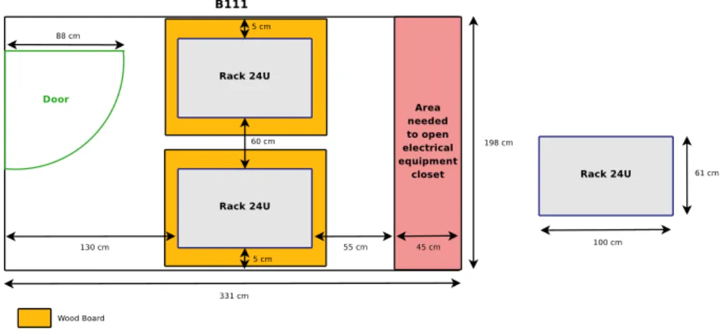
3.2.2
Racks and Weight Repartition
The floor is composed of a slab made of concrete and elevated floor. The elevated floor
supports a charge of 800 Kg per m
2, but the stab has a limit between 300 and 400 Kg per
m
2. to avoid troubles, the racks have been put on wood boards to evenly divide the weight
on a larger area and on more posts (the ones elevating the floor).
For the same reason, the racks have been placed as shown in figure 4. Each one being
side-by-side with a wall, to put the weight where the stab is the stronger.
Figure 4: Physical Deployment in the Server Room
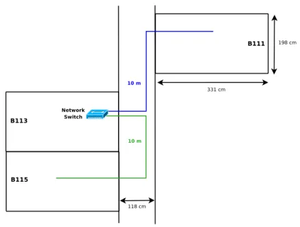
To export the display, we used two RJ45 cables of 10 meters each. The idea is to enable
the access to the platform in two offices located next to the B111, namely the B113 and
B115 offices. As shown in figure 5, the first cable is plugged in a network in the room B113,
and the second one make a bridge between this same switch and the office B115.
Figure 5: Video Export
4
Network Infrastructure
In this section, we will present the network infrastructure we deployed.
4.1
Network DSL Connections
The objective of the network telescope is to collect malwares and related information. We
expect these data to be as realistic as possible. Using the university or INRIA network, both
using Renater as ISP, would not provide the same results as users lambda would encounter
at home, because the addresses are well known, and the traffic is highly filtered. The idea
for the telescope was thus to get the same contract than home or professional users would.
We defined two scenarios:
A compagny with a /24 network
Several home users with generic DSL connections with 1 fixed public IP
To deploy these scenarios, we chose the following ISP and offers:
1 Home ADSL connection by Free
1: Internet up to 25 Mb, 29,99
¿per month.
1
1 Home ADSL connection by Neuf Telecom
2: Internet Business ADSL Illimited up
to 20 Mb, 14,90
¿per month + 3
¿per month for the modem.
1 Pro ADSL connection by Orange
3equivalent to Home ADSL offers: Internet Pro 1
Mb, 1 address, 30.82
¿per month + 49.33
¿for buying the modem.
1 Pro SDSL connection by Orange with /24 network: Business Internet Solution 1
Mb, 256 addresses, 338
¿per month + 457
¿for the installation.
We will not give the public addresses that were assigned to the telescope, to avoid being
put in blacklists by attackers. We are not interested in having high speed connections, we
only need many public IP to run as many honeypots as possible.
At the moment, all connections are operational, except the Home ADSL from Neuf
Telecom. The dedicated phone line has already been installed, and the inscription procedure
is on its way.
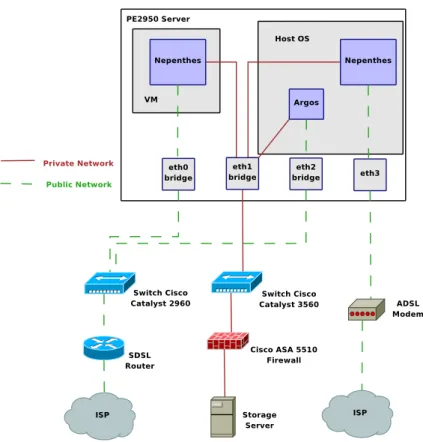
4.2
Cabling
Figure 6 shows the network infrastructure deployed for the servers of the collecting
environ-ment.
On each server, 3 bridges are set:
bridge eth0 also named xenbr0, it is the bridge that Xen will use to provide public IPs to
the VM running the Nepenthes honeypot
bridge eth1 also named xenbr1, it is the bridge that Xen will use to provide access to the
private network for attacks logging and malware storage; it will be used by the VM
running Nepenthes, the Nepenthes instance launch from Dom0 and the logging system
for Argos honeypot instances
bridge eth2 also named br0, it is the bridge that Qemu will use to provide public IPs to
the VM running the Argos honeypot
Each server will need at least 2 public IPs (one for xenbr0 and one for br0) plus 1 per
VM running Nepenthes or Argos. These two bridges are connected to the Cisco Catalyst
2960 switch, which itself is connected to the router giving access to the Internet via the ISP
network.
The bridge xenbr1 is used to access the storage network. The Argos logging system and
the Nepenthes instance run from Xen Dom0 will access directly this bridge and do not need
a dedicated IP, whereas each running instance of Nepenthes will have its own private IP
address.
The network interface eth3 will not be bridged. It will be connected directly on ADSL
modems to give access to the Home ADSL connections. As we have only 3 such contracts,
2
http://offres.neuf.fr/adsl_pro/adsl-pro-accueil/adsl-pro-offres-adsl-services-disponibles.html
3
this interface will be used on only 3 servers. The honeypot for these connections will be
instanciated directly from Xen Dom0, which is why the interface does not need to be bridged,
the ISP only giving one public IP per connection.
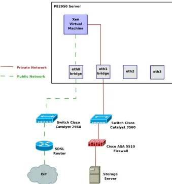
Figure 7 shows the network infrastructure deployed for the servers of the analysis
envi-ronment.
Figure 7: Network Infrastructure (Analysis environment)
In this environment, interfaces eth2 and eth3 are not used, unless they are explicitely
required for dedicated analysis. In the same way that for the collecting environment, the
xenbr0 bridge is used to connect the VM to the Internet, whereas xenbr1 is used to connect
to the storing environment.
In this case, each server needs at least one public IP, and one per running VM.
13 PE2950 servers are connected. The cabling is expressed by using the convention
<
equipment name>-<physical interface>, the physical interface being expressed by
follow-ing the constructors convent:
Cisco Catalyst 3560 - arcanine a network switch to connect the servers operating the
collect environment to the logging server
Cisco Catalyst 2960 - meowth a network switch to connect all servers from the platform
to the Internet
meowth-1 - SDSL router
Cisco Catalyst 2960 - zubat a network switch to connect the analysis environment servers
to the logging server and the Internet
Cisco ASA-SPD0 - zubat-1
zubat-13 - meowth-11
Cisco ASA 5510 - arbok the firewall protecting the storage enrivonment from infection
from the collecting or analysis environments
Cisco ASA-SPD0 - arcanine-24
dialga the main logging and storage server, connected to the PowerVault MD1000 storage
unit
Gb1 - meowth-10
Gb2 - Cisco ASA SPD1
pikachu used in the analysis environment
Gb1 - zubat-2
Gb2 - zubat-14
jigglypuff used in the analysis environment
Gb1 - zubat-3
Gb2 - zubat-15
mankey used in the analysis environment
Gb1 - zubat-4
Gb2 - zubat-16
geodude used in the analysis environment
Gb1 - zubat-5
Gb2 - zubat-17
nidoran used in the analysis environment
Gb1 - zubat-6
Gb2 - zubat-18
psyduck used in the collecting environment
Gb1 - meowth-2
Gb2 - arcanine-2
bulbasaur used in the collecting environment
Gb1 - meowth-3
Gb2 - arcanine-3
squirtle used in the collecting environment
Gb1 - meowth-4
Gb2 - arcanine-4
charmander used in the collecting environment
Gb1 - meowth-5
Gb2 - arcanine-5
onix used in the collecting environment
Gb1 - meowth-6
Gb2 - arcanine-6
togepi used in the collecting environment
Gb1 - meowth-7
Gb2 - arcanine-7
mew used in the collecting environment
Gb1 - meowth-8
Gb2 - arcanine-8
4.3
Logical Infrastructures
All hosts in the different environments have access to both the Internet, and a private
network used for attacks logging:
The collecting environment has access to the Internet in order to collect the malwares,
and to the private network for logging issues;
The storage environment has access to the Internet for reporting and software updates
and to the private network to be accessible to the other environments;
The analysis environment has access to the storage environment to retrieve the data
to be analysed and to the Internet for the experiments.
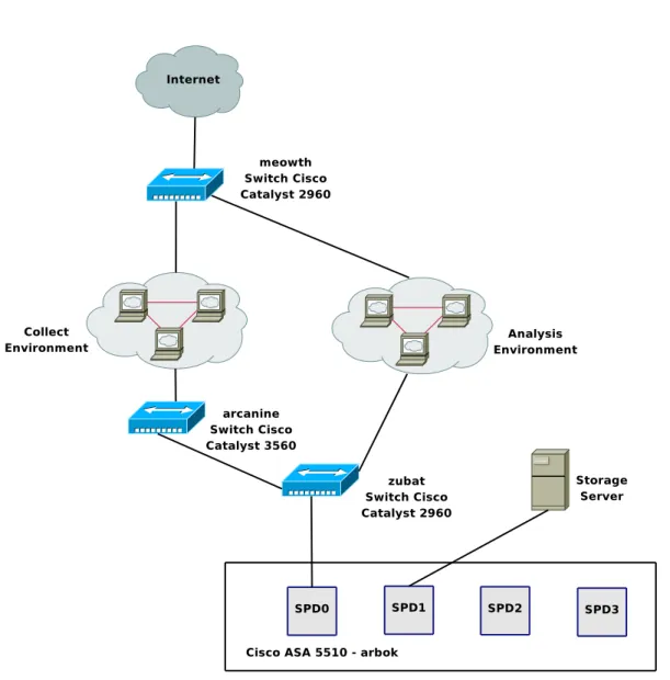
Figure 8 gives an overview of the architecture deployed.
Figure 8: Network Architecture Overview
4.3.1
Private Network
To address this network, we decided to use a private addressing based on the network
10.1.0.0/16. Each server is assigned a /24 network 10.1.X.Y/24 where X is the server Id
and Y the VM/sensor ID, Y = 1 identifying the Dom0. We separated this network in two
parts, to ease the definition of the access lists (ACL) protecting the storage environment:
10.1.0.0/17 Used for the analysis and the storage environment
10.1.128.0/17 Used for the collecting environment
The storage environment will be physically separated from the other ones via a dedicated
port on a switch or firewall, and logically (one IP address or subnet reserved). The servers
in the collecting environment have more rights to access the storage environment than the
ones in the analysis one, as they have to log the attacks in the logging server and remotely
copy the captured binaries, whereas the analysis environment may be executed by a virus
which could infect the logging server if it is not well isolated.
This gives us the following addressing scheme:
dialga 10.1.1.0/24, the logging server will thus be identified by the address 10.1.1.1
pikachu 10.1.2.0/24
mankey 10.1.4.0/24
geodude 10.1.5.0/24
nidoran 10.1.6.0/24
psyduck 10.1.128.0/24
bulbasaur 10.1.129.0/24
squirtle 10.1.130.0/24
charmander 10.1.131.0/24
onix 10.1.132.0/24
togepi 10.1.133.0/24
mew 10.1.134.0/24
We have kept the 7 to 127 identifiers reserved in case of an extension of the analysis
environment
The subnet 10.1.255.0/24 is dedicated to the network components. We will create a
virtual interface in each of them with an IP in this subnet. This interface will be used for
remote connections to the device. The addressing plane for this subnet is:
Cisco 2960 collecting environment meowth with IP 10.1.255.2
Cisco 3560 collecting environment arcanine with IP 10.1.255.3
Cisco ASA 5510 arbok with IP 10.1.255.4
Cisco 2960 analysis environment zubat with IP 10.1.255.5
4.3.2
VLANs
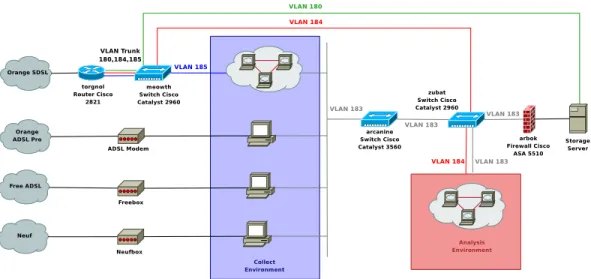
In order to separate as much as possible the different environments, we user VLANs. Figure
9 shows the deployment of these VLANs in our infrastructure.
We used 4 different VLANs:
VLAN 180 used to give Internet access to the storage server in order to get sandboxing
results and send reports
VLAN 183 used to separate the private and public networks
VLAN 184 used to give Internet access to the analysis environment
VLAN 185 used to give Internet access to the collect environment
Figure 9: VLANs Deployment
We separate all environments to ensure that they do not interfer with each other. They
are deployed on the switches as follows:
meowth
VLAN 180 on port 10
VLAN 184 on port 9
VLAN 185 on all other ports
A trunk on port 1 to the router
arcanine All ports on VLAN 183
zubat
VLAN 183 on ports 1 to 12
VLAN 184 on ports 13 to 24
Between the meowth switch and the torgnol router, we set up a VLAN trunk for VLANS
180, 184 and 185. The router has one virtual interface dedicated to each VLAN, and thus a
dedicated subnet for each vlan. The router also takes care of the traffic routing for all these
VLANs.
4.3.3
Firewalling
Cisco ASA 5510 - arbok
First of all, we have the Cisco ASA 5510 hardware firewall. It protects the storage
environ-ment from the collect and analysis environenviron-ments. Its default policy is to drop every packet
which is not explicitely permitted. It works in transparent mode, as we don’t have routing
on our private network. Figure 10 shows the architecture and cabling of this firewall. The
firewall interfaces are expressed as SPDx where x is the physical slot identifier.
Separation between the collect and analysis environments is ensured by the usage of
VLANS. The rules applied on the firewall are shown in figure 11.
Local Firewall on Storage Server
To add more security and redundancy in the firewalling, we added a local firewall on the
storage server. It has been set by using NetFilter/iptables. The script is automatically
launched at startup, and is located at /etc/init.d/local firewall.sh. The default behavior is
to drop all packet that do not match a rule to explicitely permit it. Usual protections at
kernel level are also set in this script (Bogus ICMP error messages, ping broadcast, SYN
cookies attack...). Finally, no packet is allowed to be forwarded by the storage server.
Figure 11: Firewall Rules
root@dialga:~
% /etc/init.d/local_firewall.sh status
Chain INPUT (policy DROP)
target
prot opt source
destination
ACCEPT
all
--
anywhere
anywhere
ACCEPT
icmp --
anywhere
anywhere
icmp echo-reply
ACCEPT
icmp --
anywhere
anywhere
icmp echo-reply
ACCEPT
icmp --
anywhere
anywhere
icmp echo-request
ACCEPT
icmp --
anywhere
anywhere
icmp echo-request
ACCEPT
all
--
anywhere
anywhere
state RELATED,ESTABLISHED
ACCEPT
all
--
anywhere
anywhere
state RELATED,ESTABLISHED
ACCEPT
udp
--
10.1.128.0/17
dialga.lhsi.loria.fr udp spts:1024:65535 dpt:domain
state NEW
ACCEPT
tcp
--
10.1.128.0/17
dialga.lhsi.loria.fr tcp spts:1024:65535 dpt:domain
state NEW
ACCEPT
tcp
--
10.1.128.0/17
dialga.lhsi.loria.fr tcp spts:1024:65535 dpt:www
state NEW
ACCEPT
tcp
--
10.1.128.0/17
dialga.lhsi.loria.fr tcp spts:1024:65535 dpt:https
state NEW
ACCEPT
tcp
--
10.1.128.0/17
dialga.lhsi.loria.fr tcp spts:1024:65535 dpt:ssh
state NEW
ACCEPT
tcp
--
10.1.128.0/17
dialga.lhsi.loria.fr tcp spts:1024:65535 dpt:postgresql
state NEW
ACCEPT
udp
--
psyduck.lhsi.loria.fr
dialga.lhsi.loria.fr udp spts:1024:65535 dpt:9556
state NEW
ACCEPT
udp
--
bulbasaur.lhsi.loria.fr
dialga.lhsi.loria.fr udp spts:1024:65535 dpt:555
state NEW
ACCEPT
udp
--
squirtle.lhsi.loria.fr
dialga.lhsi.loria.fr udp spts:1024:65535 dpt:9557
state NEW
ACCEPT
udp
--
charmander.lhsi.loria.fr
dialga.lhsi.loria.fr udp spts:1024:65535 dpt:9558
state NEW
ACCEPT
udp
--
onix.lhsi.loria.fr
dialga.lhsi.loria.fr udp spts:1024:65535 dpt:9559
state NEW
ACCEPT
udp
--
togepi.lhsi.loria.fr
dialga.lhsi.loria.fr udp spts:1024:65535 dpt:9560
state NEW
ACCEPT
udp
--
mew.lhsi.loria.fr
dialga.lhsi.loria.fr udp spts:1024:65535 dpt:9561
state NEW
ACCEPT
tcp
--
hobbes.loria.fr
anywhere
tcp spts:1024:65535 dpt:ssh
state NEW
ACCEPT
tcp
--
hobbes.loria.fr
anywhere
tcp spts:1024:65535 dpt:www
state NEW
ACCEPT
tcp
--
icius.loria.fr
anywhere
tcp spts:1024:65535 dpt:ssh
state NEW
ACCEPT
tcp
--
icius.loria.fr
anywhere
tcp spts:1024:65535 dpt:www
state NEW
Chain FORWARD (policy DROP)
target
prot opt source
destination
Chain OUTPUT (policy ACCEPT)
target
prot opt source
destination
ACCEPT
all
--
anywhere
anywhere
Chain PREROUTING (policy ACCEPT)
target
prot opt source
destination
Chain POSTROUTING (policy ACCEPT)
target
prot opt source
destination
Chain OUTPUT (policy ACCEPT)
target
prot opt source
destination
Chain PREROUTING (policy ACCEPT)
Chain INPUT (policy ACCEPT)
target
prot opt source
destination
Chain FORWARD (policy ACCEPT)
target
prot opt source
destination
Chain OUTPUT (policy ACCEPT)
target
prot opt source
destination
Chain POSTROUTING (policy ACCEPT)
5
Hardware and Operating Systems
In this section, we will present the hardware configuration and operating systems (OS)
installation on the PE2950 servers and the MD1000 storage unit.
5.1
PowerEdge 2950 storage and PowerVault MD1000
5.1.1
PE2950
BIOS
At boot, enter the BIOS by pressing F2. Set up the date and time to the local time. We
enable Virtualization, even if we do not plan to use it at the moment on this host. As we
only have SAS disks, we deactivated the SATA ports. The floppy drive has been removed
from the boot sequence which only contains the IDE CDROM drive and the Hard Drives in
this precise order.
Integrated RAID controller
At the boot, we enter the RAID controllers configuration utility by pressing ctrl+r, and
choosing the Perc 6/i integrated RAID controller. We have 6 SAS disks of 146 GB each for
a total raw capaciy of 876 GB. We create a RAID 5 volume with these 6 disks to obtain a
capacity of 730 GB.
Operating System
We decided to install a Linux OS based on the Debian distribution. To do so, we used the
Debian testing i386 (32 bits) CD image generated on May 5th, 2008.
We performed a ”server-like” installation by putting each important directory of the
hierarchy in a separate partition. As we have a lot of space only dedicated to the logging
server (the data itself will be stored on the MD1000 unit), we decided to spend a lot of
space in order to ensure that even in case of trouble, we will not make the OS crash. The
partitions created are as follows:
Disk /dev/sda: 731GB
Sector size (logical/physical): 512B/512B
Partition Table: msdos
Number
Start
End
Size
Type
File system
Flags
Mounting point
1
32,3kB
65,8MB
65,8MB
primary
fat16
2
65,8MB
2221MB
2155MB
primary
fat32
boot, lba
3
2221MB
12,2GB
10,0GB
primary
ext3
/
4
12,2GB
366GB
354GB
extended
5
12,2GB
22,2GB
10,0GB
logical
ext3
/var
6
22,2GB
32,2GB
10,0GB
logical
ext3
/usr
7
32,2GB
52,2GB
20,0GB
logical
ext3
/opt
8
52,2GB
62,2GB
10,0GB
logical
ext3
/tmp
9
62,2GB
162GB
100GB
logical
ext3
/home
10
162GB
166GB
3997MB
logical
linux-swap
11
166GB
366GB
200GB
logical
ext3
/backup
The partition /backup will be used to store copies of all the important data, namely the
database without the binaries and all configuration files to not lose all the data in case the
MD1000 crashes. After partitioning, we have 364.6 GB of free space left.
We followed the installation process by configuring the first Ethernet interface to use
DHCP and selecting the Graphical Environment and Base System to be installed in tasksel.
Networking and Kernel
After the installation had succeed, the system was booting on a 2.6.24-1 kernel. However,
this kernel does not support the integrated Ethernet controller. The lspci command tells us
that it is a Broadcom Corporation NetXtreme II BCM5708 Gigabit Ethernet card. This card
requires the module bnx2 to work. However, due to non respect of the Debian requirements
in terms of GNU software, this module was removed from the Debian version of the 2.6.24
kernel, which explains why it was not working.
A modified version of this driver has been added again in the 2.6.25 kernel, which we
installed. Unfortunately, it was not working either, as the associated firmware for this card
was not available.
Under the Debian unstable distribution, a new package has been added in the non-free
section. It is called firmware-bnx2. It contains the Broadcom NetXtremeII 5706 firmware
for the Linux kernel version 2.6.25. Thus, by installing the following packages, we can have
the latest kernel version with the onboard Ethernet controller working.
root@dialga:~
% apt-get install linux-image-2.6.25-2-686-bigmem linux-headers-2.6.25-2-686-bigmem firmware-bnx2
Thus, we chose the 2.6.25 kernel. As we have 8 GB of RAM and a 32 bits OS, we chose
the kernel variant with the PAE option (Physical Address Extension) enabled to support
these 8 GB. As shown earlier, we have installed the kernel version 2.6.25-2-686-bigmem.
This kernel also recognizes the 2x4 cores of our two CPUs, as shown in the result of the
command linux logo:
root@dialga:~
% linux_logo
_sudZUZ#Z#XZo=_
DDDD
EEEEEE BBBB
IIIIII
AAAA
NN
NN
_jmZZ2!!~---~!!X##wa
DD DD
EE
BB BB
II
AA
AA
NNN
NN
.<wdP~~
-!YZL,
DD
DD EEEEE
BBBBB
II
AAAAAA
NNNN NN
.mX2’
_%aaa__
XZ[.
DD DD
EE
BB
BB
II
AA
AA
NN NNNN
oZ[
_jdXY!~?S#wa
]Xb;
DDDD
EEEEEE BBBBB
IIIIII AA
AA
NN
NN
_#e’
.]X2(
~Xw|
)XXc
.2Z‘
]X[.
xY|
]oZ(
Linux Version 2.6.25-2-686-bigmem
.2#;
)3k;
_s!~
jXf‘
Compiled #1 SMP Thu Jun 12 17:11:59 UTC 2008
1Z>
-]Xb/
~
__#2(
Eight 1,86GHz Intel Pentium Xeon Processors, 8GB RAM
-Zo;
+!4ZwaaaauZZXY’
29788 Bogomips Total
*#[,
~-?!!!!!!-~
dialga
XUb;.
)YXL,,
+3#bc,
-)SSL,,
~~~~~
Securing
In order to minimize the attacks possible against the server, we deactivated all unused or
potentially dangerous services:
ident has been disabled in inetd.conf
portmap has been removed from the system
avahi-daemon has been removed from the system
cupsys has been removed from the system
The only open ports are SSH for remote connection to the server, and HTTP for remote
connection to the logging server WEB interface.
To ensure that the host has not been compromised, we installed a root kit detection
tool, rkhunter. It is executed daily and sends email reports to the local root, which we
redirected to the address [email protected] via an alias. To do so, the local MTA has
been reconfigured to send emails as an Internet site.
5.1.2
MD1000
The MD1000 storage unit contains 9 SATA disks of 500 GB each for a total raw capacity of
4,5 TB. These disks are installed in the slots 06 to 14. To configure the RAID volume, we
need to use the second RAID controller on the PE 2950 server.
To do so, we entered again the RAID configuration utility at boot, but this time we
chose the second RAID controller, the Perc 6/e, which is connected via an SAS cable to the
MD1000. The controller can handle different RAID levels:
RAID 0 Striped set without parity
RAID 1 Mirrored set without parity
RAID 5 Striped set with distributed parity
RAID 6 Striped set with dual parity
RAID 10 Mirrored sets in a striped set
RAID 50 Stripe across distributed parity RAID systems
RAID 60 Stripe across dual parity RAID systems
We aim at having at least 3 TB of disk space in our RAID volume, and have a minimum
of security. The levels 0, 1, 10, 50 and 60 are thus directly eliminated. We have to choose
between RAID 5 and RAID 6.
RAID 5 supports only 1 drive failure, and the capacity of one disk is lost for the parity.
RAID 6 uses a dual parity system to prevent the failure of a second disk during the rebuilding
of the volume after a failure. however, it uses two disks for the parity distribution, and
introduces a significant delay in the writing operations compared to RAID 5 due to the dual
parity calculation.
As our data sets are not vital, we opted for RAID 5. Nevertheless, we configured the disk
with id 06 as a global hot-spare, which means that the RAID volume will be automatically
rebuilt using this disk in case or failure. The RAID volume is thus composed of 8 drives for
a capacity of 3,5 TB. After the volume initialisation (from 8 to 48 hours, will consume the
same time in case of failure), 3,18 TB are available for the OS.
MD1000 partitioning
By default, the msdos partition table is used. This allows to create partitions of 1,3 TB
maximum. We would have to create 3 partitions to use the whole disk. It could be
interest-ing, as it would allow us to separe the nepenthes binaries/argos dumps, the network traces
and the database. However, as it is hard to predict the capacity required by each of them,
we prefer to use only one partition. The solution would be to create a LVM (Logical Volume
Manager) with these 3 partitions. But as this adds more complexity to our architecture, we
used the partition tool GNU parted instead of cfdisk.
This tool permits to use another partition table named GUID Partition Table (GPT),
which does not have the same limits than the msdos partition type, and allows to create a
partition of 3 TB or more. To create our partition of 3,18 TB we proceeded as follows:
root@dialga:~
% parted /dev/sdb
GNU Parted 1.7.1
Using /dev/sdb
Welcome to GNU Parted! Type ’help’ to view a list of commands.
(parted) mklabel gpt
(parted) mkpart
File system type? reiserfs
Start? 0
End? 3497GB
(parted) p
Disk /dev/sdb: 3497GB
Sector size (logical/physical): 512B/512B
Partition Table: gpt
Number
Start
End
Size
File system
Name
Flags
1
17,4kB
3497GB
3497GB
reiserfs
md1000
(parted)
We chose the reiserfs file system rather than ext3 because, even if there are more tools
available to manipulate ext3, it checks the file system every 30 mounts, which implie a long
delay of start up in case of crash. Opting for reiserfs ensures a faster boot, and does not
compromise data integrity.
After creating the filesystem, we have one reiserfs aprtition of 3,18 TB mounted as /data.
It will contain the database, nepenthes and argos binaries and the network traces.
To ensure a minimum of redundancy, the database will be replicated in the /backup
partition on the logging server.
5.2
PowerEdge 2950 collect and anaslysis
The installation is the same than for the Operating System on the logging server.
5.3
KVM 2161DS-2 Switch
A KVM switch (with KVM being an abbreviation for Keyboard, Video or Visual Display
Unit, Mouse) is a hardware device that allows a user to control multiple computers from a
single keyboard, video monitor and mouse. We have a KVM 2161DS-2 device connected to
all our servers. This device exports the keyboard, video and mouse over an IP network. It
allows two remote connections at the same time.
In this section, we present the configuration of this device.
5.3.1
Network
Even if the KVM switch acts as a physical barrier between the collect/analysis/storage
environments and the network on which the video data is exported, we decided to separe
this network from the Loria one, to avoid any possible mistake. We have a separated
Ethernet cable going from the servers room to the office that will operate the platform.
We set up a private network using the prefix 192.168.1.0/24. In this network, the switch
has the address 192.168.1.1. At the moment, only one computer is connected. Its name is
sloth and has the IP 192.168.1.2.
For sloth to access the KVM switch, we need to configure the network address in the
switch. To do so, we connect a computer to the switch via a console cable (configuration
9600 bps 8N1 with no flow control). By following the menus, we can set the IP address of
the switch and set the password for the administrator, the user Admin (case sensitive).
The KVM switch detects automatically the connected servers, and is now accessible via
our private network.
5.3.2
Access and Configuration
The KVM switch can be accessed by 3 different ways:
A Java Windows client
A Java Linux client
a WEB interface
The web interface is available via both operating systems. The java client authenticates
the user into the switch and then launches this web interface.
When using the java client, we must first add the KVM switch thanks to its IP address
into the database. We can then connect and rename the different servers to identify them
with their hostnames and not a generated serial number. By selecting a server, a new java
window is created with the exported display. As we have Xorg servers running on our
servers, the quality of the exported display under Windows is poor. Thus, we will use the
Linux Java client and the web interface. This solution gives a better result in terms of video
quality and speed.
We added a user madynes with password dfg1DFG with user priviledges to access the
servers without reconfiguring the switch.
To connect to the switch, use the Java Linux client and connect the switch with its address
192.168.1.1, or use the WEB interface under Linux at the URL http://192.168.1.1, and
identify ourself with the users Admin or madynes.
6
Softwares
In this section we will present the different softwares we installed in our infrastrusture.
6.1
Logging Server
6.1.1
Overview
The logging server we used is part of the Surfnet SurfIDS
4project. SURFids is an open
source Distributed Intrusion Detection System based on passive sensors. The goal is to
provide an early warning system which lets system administrators correlate known and
un-known exploits to attacks directed towards their networks. Figure 12 shows the architecture
of this project.
Figure 12: Surfnet IDS Architecture
This approach is composed of:
The logging server working with a web and database server to store and display
infor-mation about the captured malwares
Sensors acting as transparent bridges between the client network and the tunnel/honeypot
server
The tunnel/honeypot server which creates tunnels to the sensors to operate them and
collect the reports, that it redirects to the logging server
4
Third party honeypots such as nepenthes or argos which have been modified to log
into the logging server
In our infrastructure, we are only interested in the logging server and its interaction with
third party honeypots.
6.1.2
SurfIDS Logserver
The logging server consists of 2 parts, the database and a webinterface. The database is
used to store the analysis information from the honeypots. This information is presented
to the users by a webinterface. The webinterface is used to keep track of the logging, but
also the sensor status information. A secondary function of this server is the ability to send
mails in response to the logging that is received.
Several features of the webinterface are:
Attack information
Downloaded binary information
Logging export to the Intrusion Detection Message Exchange Format (IDMEF) [1]
Remote control for the sensors
Traffic monitor