BOILING AND CONDENSATION IN A LIQUID-FILLED ENCLOSURE
Avram Markowitz Arthur E. Bergles
Report No. DSR 29077-73 Missile Systems Division Raytheon Company
Bedford, Massachusetts
Archives
MAR 11
1971
02174
Engineering Projects Laboratory Department of Mechanical Engineering
Massachusetts Institute of Technology Cambridge, Massachusetts 02139
January 1971
ENGINEERING PROJECTS LABORATORY
NGINEERING PROJECTS LABORATOR IGINEERING PROJECTS LABORATO
IINEERING PROJECTS LABORAT' NEERING PROJECTS LABORK
'EERING PROJECTS LABOR - ERING PROJECTS LABO'
RING PROJECTS LAB
ING PROJECTS LA' qG PROJECTS L I PROJECTS PROJECTF ROJEC-OJEr
0
?{t fUNCLASSIFIED
Technical Report No. 29077-73
BOILING AND CONDENSATION IN A LIQUID-FILLED ENCLOSURE Avram Markowitz
Arthur E. Bergles
For
Missile Systems Division Raytheon Company
Bedford, Massachusetts, 02174
January 1971
Heat Transfer Laboratory Engineering Projects Laboratory Department of Mechanical Engineering
Massachusetts Institute of Technology Cambridge, Massachusetts, 02139
UNCLASSIFIED
BOILING AND CONDENSATION IN A LIQUID-FILLED ENCLOSURE
by
Avram Markowitz
ABSTRACT
A combined experimental and analytical investigation of boiling and con-densation in a liquid-filled enclosure, with water and Freon- 113 as the work-ing fluids, is described. The operating characteristics of a boiling system, utilizing a condenser submerged in the fluid, are presented and related to
specific operational modes and thermal transport mechanisms.
A lower bound of operation, corresponding to natural convection heat transfer at both the heated and condenser surfaces, is identified. Similarly, for the commonly encountered range of system operation, a condensive upper bound is identified and shown to correspond to vapor space condensation.
A nondimensional vapor bubble collapse length, L
/W,
is found to govern cthe rate and mechanism of heat transfer at the submerged condenser surface. L
C
Values of w<< are associated with natural convection heat transfer at the L
c
submerged condenser. For -~ I the presence of a substantial vapor
frac-w
tion in the bulk liquid leads to augmented convection, while for values of L
C
>> 1 condensation is found to dominate thermal transport at the condenser
surface.
4
possible technique for augmenting condensation heat transfer on hori-zontal surfaces is examined in an attempt to raise the condensive upper bound of submerged condenser operation. A doubly-rippled surface with small, constant radius of curvature undulations is shown to yield a factor of two increases in the rate of vapor space condensation based on the projected area of the condenser surface.A systematic design procedure for submerged condenser systems utilizing the proposed models and correlations is described and related to typical
design considerations.
ACKNOWLEDGMENTS
The investigation described herein was supported by Raytheon Company, Missile Systems Division, and performed at the MIT Heat Transfer Labora-tory while A. Markowitz was participating in the Advanced Study Program of
Raytheon Company.
The authors are indebted to Professors B. B. Mikic and P. Griffith of MIT, as well as to D. L. Cochran and A.. Owens of Raytheon Company, MSD, for their encouragement and assistance during the course of this research effort.
The generous help of F. Johnson and J. Horowitz in assembling and instrumenting the test apparatus is gratefully acknowledged.
The authors also wish to thank Annette Markowitz and the Raytheon, MSD, Publications Department for their efforts in preparing the manuscript.
UNCLASSIFIED
NOMENCLATURE
a - Acceleration
A - Area
B
-Bubble collapse parameter, Ja
_K
R 0 Ap c - Arbitrary constant
c - Specific heat at constant pressure p
Csf - Boiling constant
Cd - Bubble departure constant
D - Diameter
De - Equivalent diameter, (4 x flow area)/(wetted perimeter)
D - Bubble departure diameter F' - Buoyant force per unit volume Fr - Froude number v/4gT
Gr - Grashof number, g 8 (A T) L p
/y
g - Gravitational accelerationg - Gravitational constant, 32. 17 lb ft/lb sec2
0 m f
h - Heat transfer coefficient
h - Latent heat of condensation or evaporation hI - h +0.68 c (Ts-Tc) fg fg p s c Ja - Jacob number, c p (T s-Tb )/hfg v k - Thermal conductivity K - Thermal diffusivity, k/pc~ p L - Length
L - Bubble collapse length C
n - Exponent
hL hD
Nu - Nusselt number, k or
*
Nu - Augmentation parameter, Nu aug/Nunc
UNCLASSIFIED
P - Pressure
c 11
Pr - Prandtl number k q - Rate of heat transfer
q" - Heat flux
Q - Volumetric flow rate
r - Radius of curvature of undulation Ro - Bubble departure radius
Ra - Rayleigh number, Gr Pr
Rt - Thermal resistance
S - Distance along curved surface
T - Temperature
t - Time
t - Bubble collapse period
V - Volume
V - Enclosure Volume
e
v - Velocity
vb - Bubble rise velocity
v. - Vapor jet velocity J
W - Separation distance between heated and condenser surfaces 2
We - Weber number, r p v
/-g
x, y - Coordinate axesz - Independent variable
a - Volumetric vapor fraction
a - Angle
- Thermal coefficient of volumetric expansion
- Bubble contact angle
r
- Mass rate of condensate flow per unit width y - Bubble collapse ratio, D/D0y - Condensate film thickness in undulation trough 6 - Condensate film thickness on undulation crest
- Vapor generation parameter 0 - Configuration factor
UNCLASSIFIED
A - Modified configuration factorA - Nondimensional condensate film thickness
- Absolute viscosity p - Mass density
a- - Surface tension
T - Nondimensional bubble collapse period - Nondimensional parameter
-Angle
- Nondimensional angle
Subscripts
b - Bulk
c - Cold surface, condenser surface
e - External
f - Fluid
h - Hot surface, heater surface
i - Internal 1 - Liquid m - Mean nc - Natural convection s - Saturation T -Total v - Vapor
U NCLASSIFI ED
ERRATA
Page
i "Lc " "Lc "
1, 95 line 12, 13 and 14 - should be
w W
line 21 "increaser" should read "increase" vi line 20 's' should be 's, SAT'
line 17 'L' should be I
x, 35 Figure 19 "vapors flow . . . " should read "vapor flow" 6 Delete arrows at cover
28 line 10, 13, 14 all 'Gr' should be 'Gr ' L
32 equation 7 Pr exponent should be 5. 1 for water, 1. 0 for other fluids
36 line 3 "bouyant" should read "buoyant" line 5 "bouyancy" should read "buoyancy" 37 equation 13 'P v ' should be 'pv
38 1st equation was obtained by simplifying equation 12 47 equation 31, 32 'aug' refers to augmented
51 abssica 'J ' should be 'Ja'
52 line 27 . . is of necessity . . . " should read ". . is necessary
54 equation 46 'amb' refers to ambient
59 line 8 "A rigorous for 6 (x) . . . " should read
"A rigorous solution for 6 (x) . . .
65 line 33 "Though obviously . . ." should read "Obviously, any augmentation must be weighed . . .
UNCLASSIFIED
TABLE OF CONTENTS
ABSTRACT... ACKNOWLEDGMENTS... NOMENCLATURE... 1. INTRODUCTION... 1. 1 Electronic Cooling... 1. 2 Pool Boilers... 1.3 Submerged Condenser . .... 1. 4 Present Investigation . .... 2. OPERATING CHARACTERISTICS C APPARATUS...2. 1 Apparatus and Procedure 2. 2 Operating Characteristics 2.3 Bulk Temperature... 3. OPERATIONAL MODES...
3. 1 Mode I - Natural Convection
3. 2 Mode II - Subcooled Boiling 3. 2. 1 At the Heated Surface 3. 2. 2 In the Bulk...
Page
iv
EXPE R
3. 2. 3 At the Condenser Surface... 3. 2. 4 Condensive Limit of Mode II 4. CONDENSATION ON A RIPPLED SURFACE.
4. 1 Introduction...
4. 2 Experimental Apparatus and Procedure 4.3 Analysis. ...
4. 3. 1 At the Undulation Crest...
4. 3. 2 At the Undulation Trough...
IMENTAL 10
10
13 21 27 27 30 30 38 4355
64 64 68 6969
. . . .'. . . . 75 ViiUNCLASSIFIED
TABLE OF CONTENTS (Cont.)
4. 4 Results and Discussion . . . . 4. 4. 1 Condensate Film Thickness...
4. 4. 2 Condensive Limit. ...
5. DESIGNING A SUBMERGED CONDENSER SYSTEM... 5.1 Introduction...
5. 2 Design Considerations. .... .. ... 5. 3 Design Procedure. .... ... .. ... 5. 4 Additional Considerations
5. 4. 1 Increasing Effective Condenser Area . . . . 5. 4. 2 Presence of Noncondensables ..
5. 4. 3 Changing the Physical Scale
5. 4. 4 Heater Configuration. ...
5. 4. 5 Two-Fluid Submerged Condenser System . . . . CONCLUSIONS... ... ... .. ...
-REFERENCES... APPENDIX
EXPERIMENTAL APPARATUS AND PROCEDURE... BIOGRAPHY ,... ... ... . . ... .-.-. Page 77 77 80 83 83 84 85 89 89 92 93 93 93 100 107 Viii
iii
UNCLASSIFIED
LIST OF ILLUSTRATIONS
Figure Page
I Pool Boiler for Electronic Components with Vapor Space
Condenser (1) 3...3
2 Completely Filled Container with Submerged Heat
Exchanger . . . . 5 3 Pool Boiler for Electronic Components with Side Wall
Cooling ... ... ... ... 6 4A Side-Wall, Air-Cooled Power Supply Module (1)... 9 4B Submerged Condenser System (1) . . . . 9 5 Schematic of Experimental Submerged Condenser
Apparatus . . . . - - - . . . . . .11 6 Photograph of Experimental Submerged
Condenser Apparatus .... ... ... 12 7 Operating Characteristics of a Submerged Condenser
System - Water, One Heater . . . . 14 8 Operating Characteristics of a Submerged Condenser
System - Water, Two Heaters . . . .. . . . 15 9 Operating Characteristics of a Submerged Condenser
System - Freon-113, One Heater ... 16 10 Operating Characteristics of a Submerged Condenser
System - Freon-113, Two Heaters . . . . 17
11 Submerged Condenser Operating Mode Ia - Water,
One Heater. .... .. ... ..-.-.-.-.-.-.-.-.-.-. 19 12 Submerged Condenser Operating Mode IIb - Water,
One Heater... . - - - . .20 13 Bulk and Heated Surface Temperature Variation with
Condenser Heat Flux - Water, One Heater . . . . 22 14 Bulk and Heated Surface Temperature Variation with
Condenser Heat Flux - Water, Two Heaters . . . .. . 23 15 Bulk and Heated Surface Temperature Variation with
Condenser Heat Flux - Freon-113, One Heater . . . .. . . . . 24 16 Bulk and Heated Surface Temperature Variation with
Condenser Heat Flux - Freon-113, Two Heaters ... 25 17 Mode I - Convection in Submerged Condenser System
-~ ,~. -'~ A
~
a~
.-WARS~UNCLASSIFIED
LIST OF ILLUSTRATIONS (Cont.)
Figure Page
18 Pool Boiling of Water... 31
19
kStages in the Transition from the Region of Isolated Bubbles to the Region of Continuous Vapor Columns(vapors flow increasing from a to e) .. ... .... ... ... 35 20 Collapse Distance of Bubbles for Varying Bulk
Sub-cooling - Water, Freon-113 .. .. ... .... .... ... ... 44
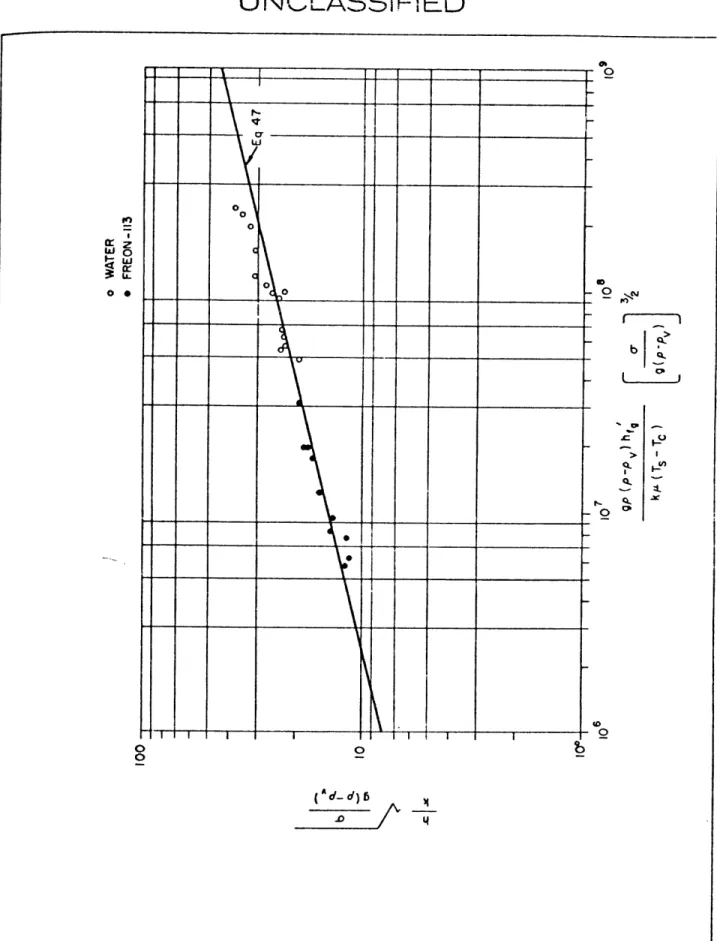
121 Variation of Condenser Heat Transfer Coefficient with
Dimensionless Collapse Length - Water, One Heater ... 46 22 Augmented Natural Convection in Water .. .. ... .... ... 51 23 Calculated Bulk Temperature Variation with Condenser
Heat Flux - Freon-113. .. .. ... .... ... .... ... ... 53
24 Condensive Limit on Horizontal Surface. .. ... ... .... ... 56 25 Model and Coordinate System for Vapor Gap Analysis. .. ... 58 26 Heat Transfer Rate as a Function of Angle at a Temperature
Difference of 40OF. .. ... .... ... ... .... ... ... 62 27 Condensive Limit on an Inclined Surface .. .. ... ... ... 63 28 Photograph of Doubly-Rippled Surface .. .. .. ... ... ... 66 29 Schematic and Coordinate System for Doubly-Rippled
Surface .. .. ... ... .... .... ... .... .... ... ... 67 30 Nondimensional Film Thickness Along Crest of Sinusoidal
Undulation... ... ... ... 74
31 Condensate Film Thickness on Crest of Sinusoidal and
Gregorig Type Profiles. .. ... ... .... .... ... .... ... 79 32 Condensive Limit for Doubly-Rippled Horizontal Condenser
Surface .. .. ... ... .... .... .... ... .... ... ... 81 33 Bulk Temperature Variation with Condenser Heat Flux
-Water .. .. ... ... .... .... ... .... .... ... .... ... 90
18
424UNCLASSIFED
1. INTRODUCTION
1. 1 Electronic Cooling
The advent of modern, high speed, high power electronic components has generated growing interest in boiling heat transfer for electronic cooling.
Most first-generation electronic devices and some of today's standard units are adequately cooled by the natural circulation of ambient air. The cooling requirements of many others can be met by the forced flow of air or other standard fluids in conjunction with highly conductive thermal paths through appropriate structural elements (so-called cold-plates, cold-bars, etc.). However, a growing number of thermal and electrical constraints can be met only by direct immersion of the components and/or devices in a
dielectric coolant chosen to provide boiling heat transfer at the heated sur-faces. This technique can be applied in two distinct electronic device cate-gories differing widely in dissipated power per unit. The first is typified by high-voltage power supplies for ground and airborne radar transmitters typically dissipating 1-5 kilowatts which must operate successfully over a wide range of environmental conditions and where volumetric and weight considerations are paramount [1]. The second is comprised of solid-state devices in high speed, data processing, logic and memory equipment typically dissipating 200-800 milliwatts where the need to reduce wiring delays [2) and the increased power consumption per gate associated with high switching frequency [3] have led to more compact devices and heat fluxes at the sub-strate level approaching 200 W/in. 2 [4].
In both of the above categories, the relatively small temperature differ-ences inherent in boiling transfer, play a crucial role in reducing thermal cycling. Substantial spatial and temporal power variations can thus be
tolerated without increasing component failure rates. In the cooling of high-power components as, for example, in temperature sensitive high-power tubes, the nearly constant surface temperature is essential to proper operation. In many memory units the maintenance of a relatively narrow temperature range
UNCLASSIFIED
at the core, despite variations in power dissipation, facilitates precise determination of the required driving current. This in turn reduces powker input to the system while, simultaneously, decreasing heat dissipation within the memory by eliminating special circuits otherwise required to compensate for thermal drift [1, 5].
1.2 Pool Boilers
In the design of pool boilers for electronic assemblies, the coolant may be considered expendable or unexpendable. In the expending type the vapor generated is allowed to escape through a pressure control valve [6]. Obvi-ously, the use of such a system is limited to tasks in which the required life is short, since the supply of liquid is rapidly depleted and as the liquid level falls, components are exposed to vapor. For systems requiring a high level of reliability and longer operating life, the generated vapor must be
con-densed and recirculated.
Initially, such cooling systems had been designed with remote condensers or condensing surfaces placed in the vapor space above the boiling fluid as shown in Fig. 1. There are, however, two major drawbacks associated with a vapor space condenser: packaging height is limited to the liquid height at minimum temperature and the presence of even small quantities of
noncon-densables (e. g., air) can cause a dramatic degradation in condenser
per-formance [7] leading to higher system pressures and temperatures.Con-sequently, elaborate filling and degassing procedures must be specified for these systems, thus increasing maintenance costs and decreasing overall
0 0 td p 0 0 0 () 0) CD 0
UNCLASSIFIED
1. 3 Submerged Condenser
It is possible, though to overcome these drawbacks by completely filling the pool boilder and incorporating an expansion chamber in the design, as shown in Fig. 2. The condenser is thus submerged at all times in the liquid and liquid level variations with temperature are eliminated. In this config-uration, the condenser surface serves primarily to subcool the liquid in the pool boilder and vapor bubbles generated at the surfaces of the dissipative electronic components rise and begin to condense in the fluid. The presence of noncondensables dissolved in the liquid reduces the collapse rate of the vapor bubbles, but the noncondensables can be removed at the submerged
condenser surface by slightly pitching the surface (~ 5*) towards the expan-sion chamber inlet. The small gas bubbles impinging on the surface slide along the surface and are vented into the expansion chamber. As a result, noncondensables do not substantially affect heat transfer at the submerged condenser surface. This is in sharp distinction with the vapor space con-denser in which the noncondensables accumulate in the vapor space and impede the flow of vapor toward the condenser surface. The elimination of the vapor space thus significantly reduces the effect of noncondensables on the thermal performance of the system and, in addition, results in considerable economics in volume and weight [8, 9] . Similar advantages can often be realized by
utilizing the side walls of the container as the primary cooling surfaces, as shown in Fig. 3, or as secondary cooling surfaces in conjunction with the
horizontal submerged condenser.
As in other boiling systems, the dissipative elements in the submerged condenser system experience only moderate increases in temperature as a result of large increases in their dissipated power. Furthermore, low dissipation or thermally passive components immersed in the bulk fluid undergo only slight changes in temperature for large variations in the total system power dissipated. The major obstacle to widespread use of this technique has been the absence of explicit information on significant design parameters and on the rate of heat transfer at the submerged condenser surface.
Fairbanks et al.
[101
have provided a basis for research in this field. Their investigation of a finned condenser submerged in water, FC-75, or a mixture of water and ethylene glycol and placed above boiling surfaces,UNCLASSIFIED
FLEXIBLE
BELLOWS
LIQUID
COOLANT
USE ABLE
PACKAGING
HEIGHT
Fig. 2 - Completely Filled Container with Submerged Heat Exchanger
EXPANSION CHAMBER '-a. 0 0 0 '-a. CD '1 0 '1 tTl '--a CD C-) '-1 0 '-a. C) 0 CD Cl) '-A. CD. '--a 0 0 I-a I-'. NT
z
cU)
-11
U
UNCLASSIFIED
revealed that in the absence of a vapor space the heat transfer coefficients at the condenser surface could attain "50% of the values that would be con-puted for normal filmwise condensation in a vapor space" [10]. A finned
copper plate with 0. 25 in. deep and 0. 125 in. wide fins spaced 0. 125 in. apart with the principal area on the vertical surface of the fins served as the
condenser surface. The system was vented to atmospheric pressure and the heat input at the boiling surfaces varied between 0. 5 and 1. 0 kilowatts,
yielding a maximum condenser heat flux based on projected area of
approxi-4 2
mately 1. 9 x 10 Btu/hr-ft2. Utilizing a trial-and-error dimensionless parameter approach, Fairbanks et al. found that data for all three fluids
could be correlated in terms of 3 dimensionless parameters:
h pvh pqc
h 2 pc (T -T ) 3 p h pL
nc s c v fg
with
1 c(42 3 x)y
to generally within 20 percent. However, the values of x, y, and c were found to vary with the number of heat sources. This latter dependence
seriously constrained the usefulness of their correlation and suggested the need for a more fundamental exploration of the thermal mechanisms active in the system.
Simons and Seely [6] investigated the relative performance of several electronic cooling systems, including a submerged condenser system, for a
particular electronic packaging configuration.
Their results indicate that at
a given condenser surface temperature more vapor can be condensed in asystem employing a vapor-space condenser than in a system relying on a submerged condenser. The difference in performance between the two systems was small and possible vapor channeling due to the particular
packaging configuration substantially reduces the generality of their results. Despite the absence of a rational design procedure, the inherent advan-tanges of submerged condenser systems have been recognized and are being presently utilized in the appropriate industrial applications. Raytheon
UNCLASSIFIED
Company, in particular, has designed a number of submerged condenser systems for cooling high-power radar components [1, 11] , as shown in
Fig. 4, and continues to specify submerged condenser systems for future applications. However, a fundamental understanding of the thermal nechan-ism active in submerged condenser systems is necessary if optimum size, cost and efficiency are to be achieved.
1.4 Present Investigation
The aim of this investigation is, then, to conduct a combined analytical and experimental study of the thermal mechanisms active in a submerged condenser system, to define its operational limits and gain explicit informa-tion on significant design parameters.
In Chapter 2 the overall operating characteristics of an experimental submerged condenser system utilizing water and Freon-113 as the working fluids are discussed and illustrated with photographs, sketches, and graphs.
The relevant thermal mechanisms are examined in detail in Chapter 3. These mechanisms are related to specific operational modes and shown to accurately define the upper and lower bounds of operation. Chapter 4 examines a possible technique for improving the upper bound of operation, and Chapter 5 incorporates the experimental and analytical results in a design procedure for submerged condenser systems.
T
UNCLASSIFIED
67-38280
Fig. 4A - Side-Wall, Air-Cooled Power Supply Module (1)
66-35190
UNCLASSIFIED
2. OPERATING CHARACTERISTICS
OF EXPERIMENTAL APPARATUS
2. 1 Apparatus and Procedure
The preceeding chapter has briefly reviewed the cooling requirements of electronic devices and components and shown that a particular need exists for submerged condenser cooling systems. However, no analytic or comn-prehensive design procedure is as yet available. In the present investigation the operating characteristics of a submerged condenser were obtained with the aid of the apparatus shown in Figs. 5 and 6.
The apparatus consisted of five cylindrical heaters, 0.25 inch in diameter, electrically powered and oriented horizontally in an insulated Plexiglas and brass container 6 inches on a side. Degassed water and Freon-113 were
chosen as the working fluids. The flat, horizontal condensing surface was at the top of the container, approximately 4. 5 inches from the heaters, and incorporated a cooling coil through which city water at nearly 60*F inlet temperature was circulated. A liquid reservoir located on top of the con-tainer served to maintain a nearly constant average system pressure of
14. 9 psi. The ratio of total heated to condenser surface area varied from 0. 14 to 0. 71 depending on the number of heaters activated. Flow meters, voltmeters, ammeters, and a stripchart recorder were used as required.
The average condenser surface temperature was determined with thermocouples located 0. 030 inch below the surface. The average heated surface temperature was determined by the use of an especially prepared, hollow, thin-walled heater with thermocouples in the center. The approp-riate extrapolations based on thermal conductivity and heat flux were made in each case to obtain the average surface temperatures. The bulk tempera-ture of the working fluid was measured by sheathed thermocouples inserted through the base of the container into the fluid.
The operating characteristics and other data were obtained in a series of data runs for each working fluid and heater configuration. Prior to each
series of runs the working fluid was carefully degassed. For each run the
-- w~m~ Orj 0 0 t!1 (D 4*
c
z
0
l
m
UNCLASSIFIED
Fig. 6 - Photograph of Experimental Submerged Condenser Apparatus
UNCLASSIFIED
heat input at the heaters and, hence, the condenser and heated surface heat flux, was maintained constant while the average condenser surface tempera-ture was varied by varying the flow of city water through the condenser
cooling coil. Further details on the experimental apparatus and procedure can be found in the Appendix. These experiments served to establish the
sequence of thermal transport mechanisms active in the submerged condenser system and defined its operational limits.
2.2 Operating Characteristics
The results of this investigation can be best understood by reference to families of operating curves relating the condenser heat flux, q", to the temperature difference, Th - Tc, between the heater and condenser sur-faces. Such operating curves for water and F-113 and 1 and 2 heaters are presented in Figs. 7, 8, 9, and 10. The four figures are seen to be essen-tially similar differing only in the magnitude of the parameters.
Examing Fig. 7, which is for I heater in water, in greater detail, it is apparent that the thermal behavior of a submerged condenser system can be bounded by a proper choice of the limiting heat transfer mechanisms in an enclosed and nearly isobaric liquid. The lower bound of operation (Mode I)
corresponds to heat transfer by natural convection at both the heated and condenser surfaces and is associated with relatively low condenser heat flux, q". As q" increases, while the condenser surface temperature T is
c c c
held constant, Th increases past the incipience temperature and subcooled boiling is initiated at the heated surface. For further increases in q', fully
c
developed boiling is achieved at the heater while natural convection augmented
by bubble pumping occurs at the condenser surface (Mode Ila). As q" iscincreased still further, the generated vapor bubbles impinge and condense on the condenser surface (Mode IIb) and heat transfer at the surface is achieved primarily by condensation.
The locus of Mode II for Tc = constant essentially follows a boiling curve but its exact shape in the isolated bubble as well as in the fully-developed boiling regions is sensitive to the degree of bulk liquid subcooling. The variation of bulk temperature with q" is examined in Subsection 2. 3.
(D (D CD
c
z
0
W
-nl
m
U
(SATURATED POOL 'BURNOUT LIMIT AT q"u13 x 104 ) 0-a 0 Cl) $1 l'1 0n
I
0 20 40 60 80 100 120 140 T1 -Tc (*F)c
z
0
W
co
1
[T
U
1600
-0
(D1
(SATURATED POOL 'BURNOUT' LIMIT AT q=
=9x
103)INCIPIENCE OF BOILING, VISUALLY OBSERVED VAPOR BLANKETING, VISUALLY OBSERVED
& 0.284 TSAT 118.5 *F 1 0D 0 0 (1 c (.) cr (D. 0 CL) (D 0 (D Cl) U) $ +
A
- /100*/ I, I I CONDENSIVE LIMIT / Ml
/0-ODE l b /-I T I
~~1~--I
/
I
80*F CONVECTIVE BOUND 0_o
*MODE Ea (MODE I) 0 10 20 30 40 50 60 70 80 T - Tc (*F DUE TO HYSTERESIS, TAKEN AS THEPOINT AT WHICH NUCLEATION CEASES
FOR DECREASING HEAT FLUX
C
-7
(5
U2
k * -'-pWme4p* , ft I -r - - mlv - I I Vok"-w-I L 1. 1 1 We IUNCLASSIFIED
The thermal behavior of a submerged condenser system is subject to one of two possible upper bounds depending on the range of system operation. For low values of T and/or low heater to condenser surface area ratios, the upper bound is established by the critical or "burnout" heat flux at the heated surface. Alternatively, high values of Tc and/or area ratios
approaching unity, result in an experimentally observed upper bound which is significantly below the critical heat flux and apparently due to a condensa-tion limit associated with vapor blanketing at the condenser surface. This sequence of heat transfer mechanisms is illustrated in the series of photo-graphs and accompanying sketches shown in Figs. 11 and 12.
Doubling the heater to condenser surface area ratio by using two heaters rather than one affects the operating characteristics only slightly as can be verified by comparing the two-heater, water data of Fig. 8 with the
one-heater, water data shown in Fig. 7.
The behavior of the system is again
seen to be bounded by a lower convective bound from which distinct T = constant curves emerge as q" increases. However, at a given value of q",c c
along a Tc = constant curve, Th is necessarily somewhat lower and slight alterations in the locus of Mode II are also apparent due to the lower heat flux, q1, at each heater.
For area ratios much greater than 1, the condensive limit dominates the entire range of operation. The maximum q decreases to a small fraction of the critical heat flux and may, in fact, fall below the flux level necessary to initiate even saturated pool boiling. The operating characteristics shown in Figs. 7 through 10 can not be expected to represent thermal behavior in
such systems. But for typically encountered area ratios, the essential operating characteristics are as shown in the above figures and are nearly independent of heater configuration.
Submerged condenser operation in Freon-113 with one and two heaters, represented in Figs. 9 and 10, was similarly found to follow the same modes and be bounded by the same operating limits but necessarily at a q" magnitude
(U)
0 e 00
*, o , 0~ 0o
FRONT VIEW SIDE VIEW
c
la: SUBMERGED CONDENSER OPERATING MODE 3a -WATER,NE HEATER (qc"=1.4 X 10⁴, Tb= 206)
Z
0
r-)>CD9
0. '1oUl)
CU)
-1
FO V0E SFRONT VIEW SIDE VIEW
FRONT VIEW 120: SUBMERGED CONDENSER OPERATING MODE 3 b -WATERONE HEATER (q .4
c 14XIO,=Tb=2IO.5)
C)
FRONT VIEW
SIDE VIEW
SIDE VIEW 12b: SUBMERGED CONDENSER CONDENSATION LIMIT -WATER,ONE HEATER (qc= 1.4 X IO,= Tb= 213)
(U) c'o 0 ) III. 0 . NJ
C
z
r)
fil
UN CLASS!FIED
2. 3 Bulk Temperature
The temperature of the bulk fluid essentially determines the temperature of the low dissipation and thermally passive elements in the system. While the operating curves relating q" to Th ~ T discussed above contain the basicc h c
system information, the bulk subcooling is only implicitly presented through its effect on the boiling curves of Mode II. More precise information on the bulk temperature is presented in Figs. 13 through 16 where Tb and Th are
related to q" at constant condenser surface temperature, Tc, for one and two
heaters in water and Freon- 113. Obviously, some care must be taken in defining the bulk temperature as significant differences exist between the temperature of the heated and condenser surface boundary layers. However, experimental measurements have shown that in the region between the
boundary layers the liquid temperature is nearly uniform (± 0. 5*F) due to convective circulation and bubble-pumping effects. It was this nearly uniform
temperature that was defined as the appropriate bulk temperature.
The curves
thus obtained are again seen to be essentially similar to each other despitedifferences in working fluid and heater configuration.
Examining Fig. 13 for one heater in water, in greater detail, reveals
that the bulk temperature increases asymptotically towards the saturation
temperature which is attained at the condensation limit. At the left of thefigure is the bulk temperature profile that would result from pure natural
convection heat transfer at the condenser surface. The experimentally determined bulk temperature profile thus gives clear evidence of augmented heat transfer at the condenser resulting from bubble pumping and condensa-tion effects.Fig. 14 for two heaters in water indicates that at the same heat flux through the condenser the value of Tb is slightly higher than for one heater but the difference is greatest in the midrange of q" and decreases as the natural connection bound on the one hand and condensive limit on the other are approached. As expected, the analogous curves for Freon-113 are similar.
0 C) 0 :j CL
o
i
D 0 q X 104 BTU/hr -ftc
z
0
C-)
r-Uo
280 11 4 2 qcX 10, BTU/hr-f t '-9. ~ Cb *1 H 0 '-9-'-1
c
z
$m"Al"Wme W~iI ~ ~ ~ WV ~ ~'1 ~ 4~m~1~ -~V~# ~ ~ ~Us'~* ~ (D30
~(D
*1 I(DN
C
z
Cf)
M-CD
160x
11Xo0, BTU/hr-1t2OTQ tdi I D o-tl (D rl+ 0 CL CD (D
c
z
cn
1
m
U,
UNCLASSIFIED
The foregoing has identified the thermal mechanisms active in a sub-merged condenser system, but considerable analytic and empirical data is necessary before a design procedure can be specified. In subsequent sec-tions, the controlling mechanisms will be examined in detail and, where possible, related to existing models and correlations.
UNCLASSIFIED
3. OPERATIONAL MODES
The operational limits and thermal performance of an experimental sub-merged condenser system were outlined in Chapter 2. However, a thorough knowledge of the specific thermal mechanisms active in the system and their possible interactions is required if the experimental results are to be used in evolving a rational design procedure. As shown in Figs. 7 through 10, a
lower bound of operation (Mode I) corresponding to natural convection heat
transfer at both the heated and condenser surfaces can be defined. Similarly, one of two possible upper bounds, corresponding to a condensive limit at the condenser surface or burnout at the heater, can be shown to exist in sub-merged condenser systems. For values of q" within the envelope ofopera-C
tion (Mode II), lines of constant Tc are found to correspond to pool boiling curves modified by subcooling effects, while pool subcooling is determined by the heat transfer rate at the condenser surface. In the following sections the controlling mechanisms in the operational modes will be explored and, where possible, related to existing correlations. The results will then be combined to yield a prediction of the performance characteristics of sub-merged condenser systems.
3. 1 Mode I - Natural Convection
At low heat flux through the heated surface, thermal transport by natural convection is sufficient to maintain the surface temperature below that
required to nucleate vapor bubbles in surface cavities. The fluid in the enclosure circulates under the influence of a thermally induced density gradient and boundary layers are formed at the heated and cooled surfaces.
The rate of heat transfer is determined by conduction through the boundary
layers at the surfaces of interest and has been studied extensively for variousgeometries and fluids as summarized in [12, 13]. Assuming side-wall effects to be negligible, it is possible to determine the rate of heat transfer through the enclosure by appropriately combining heat transfer coefficients based on
U NCLASSIFIED
the average bulk temperature at the hot and cold surfaces. For the present
configuration, heat transfer by natural convection from horizontal plates and cylinders must be examined.
Natural convection data for heat transfer from horizontal plates (hot facing up or cold facing down) can be represented as a continuous function
of Gr LPr, for which the power dependence of Nu on Gr Pr increases with increasing Gr LPr. To facilitate computation, this function is often separated into a laminar and a turbulent range. For Pr between 1 and 10
1/4
Nu = 0. 56 (GrLPr)
4 9
in the laminar flow range, 10 < Gr Pr < 10 and
1/3
Nu = 0. 13 (Gr LPr) (2)
in the turbulent flow range, 10 < Gr Pr < 10 Data for horizontal
cylinders with 103 < Gr Pr < 109 have, similarly, been found to be adequately correlated by Eq. (1) if
I-
is substituted for the length L in the dimension-less groups [7].Solving the above equations for the appropriate heat transfer coefficients, h h and h , combining these as
hheater an condenser A
(3)
T \h/ h c
to yield the overall heat transfer coefficient, httal, based on the condenser area and substituting in the thermal transport relation results in:
q" = h (T - T) (4)
c T h c
Eq. (4) is plotted in Fig. 17 for Tc = 70*F in water and found to compare favorably with data for water which were visually determined to be in the convection mode (Mode I).
C
Cb N CD CD '1c
z
C
U)
UNCLASSIFIED
3.2 Mode II - Subcooled Boiling 3. 2. 1 At the Heated Surface
As the heater heat flux increases beyond q!'. thermal transport
incip) hra rnpr
by natural convection is no longer sufficient to maintain the surface tempera-ture below that required to nucleate vapor bubbles in surface cavities. Con-sequently, despite subcooling in the bulk liquid vapor bubbles begin to grow in the superheated layer adjacent to the surface. The relation between heat flux and wall superheat is subcooled nucleate boiling is discussed in great detail in [7, 14, 15] and may be visualized as a perturbation of the saturated pool boiling curve. The saturated and subcooled boiling data for water
obtained in this investigation are shown in Fig. 18.
It is important to note at this point that typical design criteria for submerged condenser systems, including available heat sink temperatures and the need to reduce condenser surface area, usually operate to restrict liquid subcooling, and, hence, the magnitude of the perturbation on the
saturated pool boiling curve is generally small.
The initial portion of the saturated boiling curve is associated with
natural convection and can be successfully correlated as:Sq"
h =h
(T - T)
h s(5)
where the heat transfer coefficient is evaluated from the natural convection
data. The presence of pool subcooling can be simply accounted for by an
additional temperature driving force as:
q = h [(Th -T) + Tb)] (6)
where h is evaluated from natural convection data [15] . For some geometries
it may be necessary to include a cross flow velocity, due to additional fluid circulation effects, in the determination of the heat transfer coefficient
[
4]I
f
UNCLASSIFIED
Fig. 18 - Pool Boiling of Water 31
UNCLASSIFIED
The wall superheat required to initiate the growth of vapor bubbles in degassed liquids is dependent on the heater surface characteristics, fluid properties and pool subcooling. A precise determination of the nucleation
superheat or of the heat flux required to initiate bubble growth on an arbitrary surface is not yet possible. Alternately, it is possible to locate the nuclea-tion point, with reasonable accuracy by smoothly joining the natural convec-tion curve and the full-developed boiling curve, as shown in Fig. 18. The
visually determined boiling incipience points are seen to lie above the
con-vective curves, suggesting the presence of some additional circulation effects previously neglected. It must be noted, moreover, that visual incipience, can-not generally be expected to correspond to true incipience, but may be found to lie somewhat further along the boiling curve.
While the water data shown in Fig. 18 does not evidence any tem-perature discontinuities, the phenomenon of temtem-perature hysterisis is a
major concern in the boiling of many fluids including Freon-113 [4]. When temperature overshoot hysterisis is present, convective heat transfer
per-sists past the intersection of the convective and fully-developed boiling curves and suddenly reverts to fully-developed boiling along the entire sur-face. This behavior is thought to result from the existence of metastable vapor bubbles and the quenching of large cavities during subcooling [4] . The
likelihood of boiling hysterisis in some surface-fluid combinations,
necessi-tates the use of the decreasing-heat-flux boiling curves in discussing theirboiling characteristics.
Heat transfer in saturated pool nucleate boiling has been correlated by several investigators. One of the more widely used correlation was developed by Rohsenow [7] and based on a bubble-pumping mechanism. The correlation, shown below, utilizes one empirical constant, C , evaluated for each surface-fluid combination.
C3
q" 1
P
g(p 1 -p) (T - T ) (7)3 h r5.4
w
s
Cf hf3Pr ga
UNCLASSIFIED
A considerable number of values C have been determined and tabulated by investigators of boiling phenomena. However, for many surface-filuid
combinations of interest, C must be determined experimentally, if an accurate prediction of boiling transfer is desired. Hence, the correlation is of limited utility unless used to extrapolate experimental results to other pressure levels.
While some success has thus been achieved in correlating and describing saturated pool boiling, a description of the precise effects of subcooling has so far eluded investigators. As shown in Fig. 18, the data for moderately subcooled pools deviate to some extent from the saturated pool data. However, the direction and magnitude of this shift appears to depend strongly on heater geometry and pool convective conditions [15] . For tubular heaters the subcooled boiling curves cross the saturated curve and in the fully-developed region yield higher wall superheats than the
saturated curve. This trend is apparent in Fig. 18 and is in agreement with earlier investigations [16, 17] . Subcooled boiling curves for horizontal flat plates, on the other hand, do not cross the saturated curve and yield wall superheats which are lower than the saturated wall superheats over the entire range of nucleate boiling [18] . Due to a scarcity of data and the inability to precisely identify induced circulation effects, it is thus essential that an experimental determination of the subcooling effects be made for each
geometry of interest.
The peak, critical or burnout heat flux marks the end of the nucleate boiling regime. In spite of substantial research there is still no universal
explanation for the phenomenon, as even carefully controlled experimental data show considerable scatter. The critical heat flux is known to depend on many factors including the pressure, induced convection effects, diameter and orientation of the heater, but it is especially sensitive to the degree of bulk subcooling.
Zuber's [ 19] assumption that the critical heat flux results when sufficient liquid can no longer flow past the vapor columns to the heated surface due to the hydrodynamic instability of the liquid-vapor interface, suggests that qr can be set equal to:
UNCLASSIFIED
S
0
.1
8
h
[ g g _ _ u(p-
_p ) 11/-
4 -P
1/ 2
crit
v fg
[
2
p
J
(8)
Experimental results for many fluids are close to the range of magnitude indicated by this relation [14] . In the present investigation saturated pool
burnout for a 0.25 inch OD, horizontal cylindrical heater in water was achieved at approximately 4. 3 x 10⁵ Btu/hr-ft2 versus 4. 9 x 10⁵ predicted by Eq. (8).
For the boiling of subcooled liquids, Ivey and Morris [20] proposed the simple expression:
1/4
crit, sub + 0. 1 -- I
--
b (9)
crit, sat T1 h p
Heat transfer in the isolated bubble regime for moderate subcooling, as well as saturated pool conditions, results primarily enthalpy transport by vapor bubbles departing from the surface [15, 21]. For heater heat flux,
q1, slightly greater than the incipience flux, qci and for moderately
ho incip'
subcooled pools, vapor bubbles formed in isolated surface cavities, depart from the surface individually. However, as the flux increases and more surface cavities are activated, the process of vapor removal from the
surface changes from an intermittent to a continuous one and vapor columns form [22] . The stages of transitions are illustrated in Fig. 19, and have been related by Moissis and Berenson [22] to the decreasing bubble separa-tion with increasing vapor flow. Utilizing expressions derived by Moissis and Griffith [23] for consecutive bubble agglomeration, it was shown [22 that, for typical surface finishes, the transition heat flux for saturated pool boiling can be expressed as:
0.5
o
1/4
UNCLASSIFIED
0
G
0
oC
0
b
Lb
(a) (b) (c) (d) (e)Fig. 19 - Stages in the Transition from the Region of Isolated Bubbles to the Region of Continuous Vapor Columns (vapors flow increasing
from a to e)
[
22]
35UNCLASSIFIED
The transition flux for a subcooled pool can be expected to differ from this result, but for moderate subcooling the difference should not be substantial.
Bubble departure in isolated bubble boiling is governed by bouyant, dynamic and surface tension forces. Fritz [24] , on the basis of earlier work,
equated surface tension and bouyancy forces at departure, and obtained rela-tion for the departing bubble diameter as:
1/2 g
o-D = cd %F2 [ ( (
0g {P~Pv
where cd was found to be 0.0148 for H2 and H2O [13].
Eq. (11) provided an adequate departure criteria, but more recent efforts have further refined the correlation by accounting for dynamic effects.
In particular, Cole and Rohsenow [25] have included data with substantial pressure variation and proposed that the departure diameter for saturated pools be expressed as:
g a pc T 5/4 D
o
= c o p s (12) [~.g
(p-pv
[Pvhfg
where -4 c = 1. 5 x 10 for waterc = 4.65 x 10~4 for other liquids
and showed Eq. (12) to be in good agreement with available data.
In subcooled pools, the reduction in bubble growth rate and the con-sequent decrease in the inertia of the surrounding liquid acts to increase the departure diameter. However, the increased pool circulation and greater buoyant force acting on the departing bubble can be expected to lead to some-what smaller departure diameters. These possible effects have not been fully studied and no correlation for the influence of subcooling on the bubble departure diameter exists at this time.
UNCLASSIFIED
The total number of bubbles generated at a particular heat flux, q1, is far more difficult to determine. While departure frequency and nucleation site density data can be combined to yield an approximate result, the departure frequency is not constant [ 26] and, as yet, no practical method exists for predicting the nucleation site density. Alternately, it is possible to estimate the rate of vapor generation as some fraction of the heat flux, according to:
Q
v _hq''
(13)
A pvhfg
where
r
0 for high subcooling and low heat flux but for q h greater than 20 percent of the critical heat flux q > 0. 5 [27] and increases to = 1 at the critical flux.For heat flux, q h, greater than qlr, vapor columns rooted in the boiling surface appear. Initially, the diameter of the columns is equal to the departure diameter of the bubbles, but with increasing heat flux the
column diameter increases to accommodate vapor flow [22] . In a recent
study, Gaertner [28] found that in post transition (q1 > q saturated pool boiling, vapor ''mushrooms'' each fed by several vapor columns appeared above the boiling surface. Observations in this investigation showed a
similar trend and the cylindrical heaters used appeared to be nearly vapor blanketed on the upper surface for high flux rates. The vapor bubbles thus formed were substantially larger than pre-transition bubbles and appeared similar to bubbles formed in film boiling. Studies by Zuber [19, 29] and Berenson [30] indicate that in film boiling the diameter of vapor bubbles formed at the liquid-vapor interface is within the range:
r
a
1/21/
3. 14 g0 (- 1v 2 D 5. 45 [g 04a
1/2
(14)g (p I - pv) 0 g (P I - Pv)_
The average diameter is thus approximately four times the departure diam-eter in the isolated bubble region (Eq. (12)) and is in qualitative agreement with the observations.
UNCLASSIFIED
3. 2. 2 In the Bulk
In the subcooled boiling mode (Mode II) the vapor bubbles generated at the heater surface rise and condense in the bulk liquid. Their height of penetration into the liquid, and consequently their effect on heat transfer at the condenser surface, is directly related to their initial diameter, rise velocity, and the prevalent collapse mechanism.
3. 2. 2. 1 Departure Diameter
As noted above, the available correlations indicate that the departure diameter varies from approximately
gu 1.1
g (p - V
in isolated bubble boiling from typical surfaces, to perhaps four time that value in columar boiling when vapor "mushrooms" cover the surface.
3.2.2.2 Rise Velocity
The rise of vapor bubbles is, as all else in boiling transfer, difficult to evaluate. The rise velocity of an undisturbed bubble in the diam-eter range of interest can be approximated [31] as:
Vb 1/3 N 2gD (15)
However, the presence of neighboring bubbles, fluid circulation, and slide walls can exert a profound influence on the rise velocity. These and other influences have been qualitatively and sometimes quantitatively evaluated, but their combined effect on bubble rise velocity can not yet be predicted.
3. 2. 2. 3 Collapse Mechanism
The mechanics of vapor bubble collapse under spherically symmetrical conditions have received extensive attention. Recent investiga-tions [3 2, 33, 34] have shown that the collapse mode was controlled alternately
UNCLASSIFIED
by liquid inertia, heat transfer or both, depending on system conditions. The effects of noncondensable gas and translatory bubble motion have also been recently incorporated into the appropriate bubble collapse relations [32]
A dimensionless parameter, B, B Ja2 q (16) where cp (Ts - Tb) Ja = f
~
h fgpvrepresenting the ratio of the time duration of inertia effects to that of heat transfer effects in the collapse process has been defined [34] and found to characterize the prime mode of collapse. For B < 0. 05 heat transfer dominates the collapse process while a value of B > 10 indicates the pre-dominance of inertia effects.
Inertia controlled collapse is governed by the classical Rayleigh solution [34] 1 3/2 T 1 31 2/ dx (17) J (1-x where T 21/2 I R 3 p R R 0
The collapse rate is high and continues to increase as the collapse proceeds. Translatory motion does not materially affect the collapse rate in this mode, but the presence of a noncondensable gas can substantially reduce the rate of collapse. Cavitation bubbles and vapor bubbles collapsing in highly subcooled liquids appear to be primarily inertial controlled.
UNCLASSIFIED
Heat transfer controlled collapse is governed by:
T 2 . 1 y (z)) y (z)
1
=1/2 JaT
dz
(18)
0 [ y (y)dy] z T Kt ,y R/R R 0An exact solution for Eq. (18) can be obtained by direct numerical integra-tion [32] . Alternately, it is possible to obtain an upper bound on the collapse rate by assuming the existence of a thin thermal boundary layer and utilizing the Plesset-Zwick temperature integral [35] . The latter approach [34]
yields a manageable expression for y as: 1 2 2 T h 3 3 y + - - 3 (19) where 4 2 Kt Th= - Ja h T R 2
In this mode, the collapse rate is relatively slow and decreases further as collapse proceeds. Translatory motion of the bubble, such as usually results from buoyancy, increases the collapse rate, especially when the liquid sub-cooling is small and the collapse rate slow [32] . The presence of noncon-densables always retards the collapse, but its effect is manifested earlier when the translatory velocity is high and is, in any event, a highly nonlinear influence on the collapse rate [32] . Bubbles collapsing in moderately
sub-cooled liquid (Ja 50) are predominantly heat transfer controlled and it is, hence, this mode which is of prime importance in submerged condenser
systems.
UNCLASSIFIED
Due to the asymptotic nature of heat transfer controlled collapse, no precise criteria exists for the definition of a collapse period. However, since it is the bubble volume which is of prime interest, and at y = 0. 2 the bubble volume is only one percent of its departure volume, the collapse period Tc can be defined as:
T ( + y2 - 3) 2.3 (20) c 3y y = 0. 2 and
2. 3
or c 4 Ja2 KIt must be further noted that the use of Eq. (19) and the neglect of transla-tional velocity effects have yielded a strictly conservative collapse criteria
(in the absence of noncondensables).
3. 2. 2. 4 Height of Penetration
Utilizing the above relations for bubble departure diameter, rise velocity and rate of collapse, it is now possible to determine approxi-mately the height of penetration of the vapor bubbles and the approximate vapor fraction in a moderately subcooled liquid-filled enclosure free of noncondensable gas.
The collapse length L equals: c t L f vb dt (21) 0 Substituting 4 2 K T -T Ja R 2 -t (22)
UNCLASSIFIED
into Eq. (21) Ro 0T C 4 Ja 2 KI
c
Vb d T( Introducing Eq. (15) R 2 LC 2K 4 Ja KI
C
0 R 2 C Ja K2 q-NJDd T c NTD d T y = D/D0 R 2 gc L c =KJgD
Ja2K0f D 5 C L 7T 0I
f Lc 8 2 K JaK K 0Numerical integration of the integral yields:
NJy d T yd T T =2. 3 f Ny dT= 1. 38 (28) And, therefore D 5/2 C