HAL Id: in2p3-00919657
http://hal.in2p3.fr/in2p3-00919657
Submitted on 17 Dec 2013HAL is a multi-disciplinary open access
archive for the deposit and dissemination of sci-entific research documents, whether they are pub-lished or not. The documents may come from teaching and research institutions in France or abroad, or from public or private research centers.
L’archive ouverte pluridisciplinaire HAL, est destinée au dépôt et à la diffusion de documents scientifiques de niveau recherche, publiés ou non, émanant des établissements d’enseignement et de recherche français ou étrangers, des laboratoires publics ou privés.
Ion sources at GANIL
R. Leroy, C. Barué, C. Canet, M. Dubois, M. Dupuis, F. Durantel, J.L.
Flambard, G. Gaubert, S. Gibouin, C. Huet-Equilbec, et al.
To cite this version:
R. Leroy, C. Barué, C. Canet, M. Dubois, M. Dupuis, et al.. Ion sources at GANIL. 17th International Conference on Cyclotrons and their Applications, Oct 2004, Tokyo, Japan. pp.1-5. �in2p3-00919657�
ION SOURCES AT GANIL
R. LEROY, C. BARUE, C. CANET, M. DUBOIS, M. DUPUIS, F. DURANTEL, J-L. FLAMBARD, G. GAUBERT, S. GIBOUIN, C. HUET-EQUILBEC, Y.HUGUET, P. JARDIN, N. LECESNE, P. LEHERISSIER, F. LEMAGNEN,
J.Y. PACQUET, F. PELLEMOINE, M.G. SAINT LAURENT, A.C.C. VILLARI GANIL, Bd H. Becquerel 14076 caen cedex 5, FRANCE
O. BAJEAT, S. ESSABAA, C. LAU, M. DUCOURTIEUX IPN Orsay BP 1 F – 91406 Orsay, France
F.G. NIZERY CEA/DAPNIA, Saclay, France
Abstract
The GANIL produces since many years heavy ion beams with Electron Cyclotron Resonance ion sources. Different facilities have been constructed during the last years in order to allow experiments in a large range of energy (from some tens of kV to 100 MeV/nucleon). The list of available ions has been greatly extended with the construction of the SPIRAL1 facility that produces and accelerates radioactives ions . An overview of the different developments made at GANIL for stable and radioactive ion beam production including the sources for the SPIRAL2 project is given in this paper.
THE PRODUCTION OF STABLE ION
BEAMS AT GANIL
Metallic ion beam developments for the high
energy beams.
Two sources are devoted to the production of stable ion beams for nuclear physic experiments: The ECR4 developed at GANIL, and an improved version "ECR4M" [1] characterized by a stronger magnetic confinement. Both sources work at 14 GHz. The first one is placed on a high voltage plate-form to extract the beam up to 100 kV, and the second one has a 25 kV mono-gap extraction system.
Intense ion beams from gaseous elements are easily and routinely produced by these ion sources. However, the production of intense beams of metallic elements is delicate for the following reasons :
• evaporation of the sample :
most of the time, the metallic element to ionize is under solid form. It must be evaporated into the source plasma. Although high intensities can be produced with the oven method (80 µA Ca11+) [2], it becomes more difficult for low vapor pressure elements. Nickel is a good example : increasing the production of nickel by increasing the oven temperature (typically above 1500°C) would prematurely damage the oven.
• ionization efficiency :
since most of the metallic atoms or ions condense on the cold plasma chamber walls, the evaporation rate has to be higher compared to gas operation : the metallic consumption is typically 10 times higher for a given intensity level. This high consumption is not compatible
with the use of rare and expensive isotopes, mostly requested by physicists. The ionization efficiency has to be as high as possible.
• beam stability :
The chemical reactivity of metallic atoms condensed on the plasma chamber walls influences the source stability. For example, strong chemical getter effects have been observed when using a mixing gaz, leading to uncontrollable intensity flushes.
Two methods of production of the metallic vapors are mainly used at GANIL: the "oven" and the "MIVOC" methods. A complete overview of the methods tested and used at GANIL can be found in reference [3] and an updated list of available beams can be consulted on our web page www.ganil.fr.
The oven method
This method is well suited to elements having a vapor pressure between 10−3
and 10−1
mbar for a temperature lower than 1500°C and higher than 300°C. Above 1500°C the components of the oven (heating wire and crucible) are quickly damaged, decreasing drastically the life time of the oven. Below 300°C the evaporation is dominated by plasma heating, due to the location on axis of the oven. Most of the metallic ion beams are produced with the oven technique at GANIL (Mg, Ca, Pb, Sn, etc...) during long term runs and an updated list of available beams can be consulted on our web page www.ganil.fr.
Two new ovens are under developments. The first one called HCO for high capacity oven is based on the concept of the micro oven and presents a bigger inner diameter in order to increase the weight of the sample that has to be evaporated, increasing by this way the duration of the run. The second one deals with very high temperatures and the goal consists in reaching 2000°C in order to allow the production af refractory elements like Uranium for example (see Figure 1).
The MIVOC method
The MIVOC method is based on the use of high vapor pressure metallic volatile compounds at room temperature. For example, nickelocene (Ni(C5H5)2) has a
vapor pressure of 3.5 10-3 mbar at 20°C. This method is now routinely used at GANIL for the production of nickel beams at high intensity : a maximum intensity of 70 eµA has been obtained for natural nickel on charge state 9+
and at 20 kV extraction voltage. The total extracted current from the source was 5 emA.
More information can be found in references [3] [4].
Figure 1: Sketch of the high temperature oven.
PRODUCTION OF HIGH CHARGE STATE
STABLE ION BEAMS FOR ATOMIC
PHYSICS: THE LIMBE FACILITY WITH
THE SUPERSHYPIE ION SOURCE.
The LIMBE facility is an apparatus located in a building very close to the cyclotrons of the GANIL. It offers to physicist the possibility to make experiments with beams at the energy corresponding to the extraction voltage (<Q*25 kV). It is equipped with the SUPERSHYPIE ion source that is an upgrade of the ECR4M source[1].The SUPERSHYPIE ion source
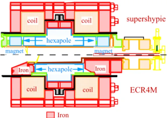
The idea of the upgrade of our ECR4M ion source consists in changing the length of the plasma by associating permanent magnets with coils to define the axial magnetic field. The axial permanent magnets (with a radial magnetization) create a modulation of the field that increases the maxima B given by the coils.
Thus, the 12 cm long at injection and 9 cm long at extraction iron pieces of ECR4M that concentrated the magnetic flow delivered by the coils have been removed and replaced by two 5 cm long permanent magnet rings and two hexapolar rings have been added in the free places. ECR4M supershypie hexapole hexapole Iron coil coil coil coil magnet magnet Iron Iron
Figure 2: drawing of ECR4M and supershypie.
This has allowed the increase by a factor 1.5 of the length of the hexapole. The design of the plasma chamber has been considerably simplified as it is now constitued of a double wall cylinder.
The source has been tested with our existing 14.5 Ghz transmitter and an example of the charge state distribution obtained with Ar is given in Figure 3.
0
5
10
15
20
25
I
CF(µAe)
particle repartition (%)
7+ 8+ 9+ 10+ 11+12 + 13+ 14+ 15+Figure 3: Argon charge state distribution when the source is optimised for Ar12+ production. PHF=1060 W, extraction
voltage=18 kV.
Numerous experiments have been run on the LIMBE facility and Table 1 resumes the intensities that have been obtained just after the first analysing magnet.
Ion Intensity (eµA) Ion Intensity (eµA) He+ 1500 Ar8+ 250 He2+ 1500 Ar14+ 23 C4+ 250 Ar16+ 1.9 O6+ 450 Ar17+ 0.08 O7+ 140 Ar18+ 4.10-4 N7+ 3.5 Kr16+ 50 Ne8+ 170 Kr24+ 5.2 Ne9+ 14.5 Xe23+ 11 Ne10+ 1.2 Xe27+ 4.2
Table 1: Intensities (eµA) of the SUPERSHYPIE ECRIS measured after the analyzing dipole
RADIOACTIVE ION BEAM
PRODUCTION
The SPIRAL facility
Production of radioactive ions has started at GANIL on the SPIRAL facility since 2001 and numerous multicharged radioactive ion beams have been delivered for high energy nuclear experiments. The production principle consists in fragmenting the high energy heavy ion beam delivered by the GANIL cyclotron in a carbon target and to ionize the reaction product inside an ecr ion source called Nanogan3.
The Nanogan 3 configuration
In order to allow the futher acceleration by the cyclotron, a compact multicharged ion source has been developped and coupled to a carbon target (see Figure 4) The target is heated by the primary beam up to 2200°C. In the case of a low beam power, an extra ohmic heating can be added through the axis of the target to maintain the diffusion of radioactive atoms.
After diffusion, the radioactive atoms effuse to the ion source through a cold transfer tube that makes a chemical selection as the main part of the non-gaseous elements sticks on the walls of the tube. The atoms then enter into the plasma of the ion source.
This source, called NANOGAN3, is a 10 GHz electron cyclotron resonance ion source with a magnetic field totally induced by permanent magnets (Figure 4). The source has been described in details in reference [5]. The choice of permanent magnets has been driven by the cost and the compacity of the source that limits the volume of radioactive waste after irradiation.
Total ionisation efficiencies –ie sum of the efficiency of each charge state- greater than 95% have been measured for different gases (Ar, Ne, Kr) with a calibrated leak during the presence and the absence of the primary beam. A comparison of the charge state distributions of stable argon during different moments of the production shows that after a short delay of out-gassing the behaviour of the source is no longer affected by the presence of the hot target in its neighbourhood.
radioactive ion beam permanent magnets carbon target thin window HF Injection (10 GHz) primary beam transfer tube
Figure 4:The Nanogan 3 configuration
A eighteenth of target ion sources have now been irradiated on the SPIRAL facility for the production of radioactive argon, neons and kryptons during 15 days with till 1.4 kW of primary beam power. A new target has been developed for 6He and 8He production which is divided into two parts because of the long range of He in carbon (see reference 6). In all cases, it has not been observed any decrease of the multicharged radioactive ion beam intensity during the long term irradiation that proves that the permanent magnets have not been damaged. The two first irradiated ion soures have been dismounted in order to change the target. The magnetic fields of these sources have been measured before and after irradiation and no significant change has been observed.
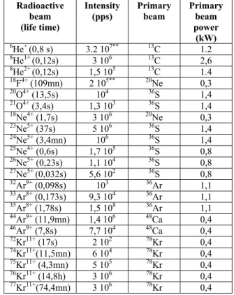
Table 2gives the intensities of the beams before or after acceleration on the SPIRAL facility.
Radioactive beam (life time) Intensity (pps) Primary beam Primary beam power (kW) 6 He+ (0,8 s) 3.2 107** 13C 1.2 8 He1+ (0,12s) 3 106 13C 2,6 8 He2+ (0,12s) 1,5 105 13C 1.4 18 F4+ (109mn) 2 105** 20Ne 0,3 20 O4+ (13,5s) 104 36S 1,4 21 O4+ (3,4s) 1,3 103 36S 1,4 18 Ne4+ (1,7s) 3 106 20Ne 0,3 23 Ne5+ (37s) 5 106 36S 1,4 24Ne5+ (3,4mn) 106 36S 1,4 25 Ne4+ (0,6s) 1,7 105 36S 0,8 26 Ne5+ (0,23s) 1,1 104 36S 0,8 27 Ne5+ (0,032s) 5,6 102 36S 0,8 32 Ar9+ (0,098s) 103 36Ar 1,1 33 Ar8+ (0,173s) 9,3 104 36Ar 1,1 35 Ar8+ (1,78s) 1,5 108 36Ar 1,1 44 Ar9+ (11,9mn) 1,4 106 48Ca 0,4 46 Ar9+ (7,8s) 7,7 104 48Ca 0,4 72 Kr11+ (17s) 2 102 78Kr 0,4 74 Kr11+(11,5mn) 6 104 78Kr 0,4 75Kr11+ (4,3mn) 5 105 78Kr 0,4 76 Kr11+ (14,8h) 3 106 78Kr 0,4 77 Kr11+(74,4mn) 3 106 78Kr 0,4
Table 2:Radioactive ion beam intensities produced on the SPIRAL facility. The intensities marked with two stars are measured after acceleration while the other ones are measured before acceleration.
Further developments for the SPIRAL facility:
The MONONAKE configuration for radioactive
alkali ion production
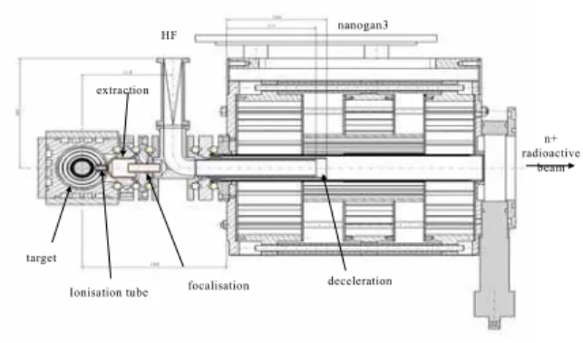
The present limitation of the NANOGAN 3 configuration is due to the cold transfer tube between the target and the plasma of the ion source. This configuration presents the advantage to make a chemical selection and to eliminate the isobaric atoms that can condense on the the tube before ionisation. However this advantage becomes a disadvantage for condensable radioactive ion beam production like for example for alkali elements. For multicharged alkali ion production, a solution consists in coupling a monocharged ion source to the NANOGAN 3 ion source. Figure 5 shows a design of the NANONAKE configuration. It consists in two sources. The first one is an upgrade of the MONOLITHE ion source that has been described in reference 7: the target is placed in a heater and the atoms can only escape through a hot tungsten tube where the alkali elements are ionised in the single charge state by surface ionisation process. The ions are then accelerated and injected into the NANOGAN 3 ion source with an energy just sufficient to drop the plasma potential barrier and to stop inside the plasma of the ECR ion source. The multi-ionisation process occurs and a multicharged ion beam can be extracted from the NANOGAN 3 source. In order to allow the injection of the 1+ ion beam in the ecr ion source, the HF injection
has been changed and replaced by a circular waveguide that can be biased and is surrounded by a grounded electrode in order to decelerate the beam in the ecr source and to tune precisely the energy of the monocharged ion beam (see Figure 5).
This configuration is constructed and the first off-line tests have began. The first test has consisted in checking that the ionisation of the multicharged ion source is not perturbated by the neighborhood of the 1+ ion source. In comparison with the nanogan3 configuration, the same charge state distribution with the same efficiency has been obtained for Ar. The second part of the off line test will consist in testing the charge breeding process by injecting a Lu powder in the production target, heating and ionizing the Lu vapor and injecting it in the ecr ion source. At least a third test is envisaged by injecting a radioactive ion beam inside the target and by measuring the different charge states of the radioactive element after the SIRa separator.
target Ionisation tube extraction nanogan3 HF focalisation deceleration n+ radioactive beam
Figure 5:The nanonake configuration for alcali elements. This method allows to obtain the overall efficiency of the system and has soon been used for measuring the diffusion properties of the SPIRAL targets. These tests will occur during the next year before implementation on the SPIRAL facility. It has to be noticed that the present design permits to be installed on SPIRAL without any modification of the production cave and can be removed with the existing remote controlled system.
Radioactive ion sources for The SPIRAL2
project
To explore the production of heavy neutron-rich nuclei with suitable intensities, the method of production has been reviewed and it appears that the fission of uranium induced by neutrons with an energy of around 40 MeV can lead to interesting production rates for heavy neutron rich elements like Xe or Sn (see reference 8). The SPIRAL 2 project consists in building a new accelerator for the primary beam coupled to a new radioactive ion production area. The rare isotope beams are produced via the fission process, with the aim of 1013 fissions/s at least, induced either by fast neutrons from a C converter in a UCx target, or by direct bombardment of fissile material. The driver, with an acceleration potential of 40 MV, will
accelerate deuterons with an intensity up to 5 mA (200 kW of beam power). In the future, heavy ions with mass-to-charge ratio A/q=3 (intensity up to 1 mA) and even higher A/q ions (up to 6) will be accelerable in order to acces to fusion-evaporation nuclear reactions. After production, the radioactive ion beam is injected in a charge booster to increase the charge state and after is injected in the present CIME cyclotron for acceleration. A detailled description of the project including the accelerator is given in reference 9 and is available on the GANIL web site www.ganil.fr.
For the radioactive ion beam, the production system needs some sources that have to be efficient in term of ionisation and radiation resistivity. The sources are coupled to the uranium target placed in front of a rotating wheel that permits the creation of the fast neutrons needed for fission of the target.
THE ION SOURCES FOR THE
RADIOACTIVE
ION BEAM FORMATION
The key word for an ion source in case of radioactive ion beam production is the efficiency. This efficiency is variable depending on the chemical element that has to be ionised and on the type of ion source that is used.
In case of SPIRAL 2, it looks clear that to fully profit from this facility, the largest choice of radioactive beams is wished. That is the reason why different ionization ways are considered depending on the chemical properties of the radioactive elements.
The ECR ion sources
This kind of sources is paticularly efficient for the production of gaseous elemens such a noble gases of gaseous compounds.At that time, no ECRIS tested on-line respects the features requested for SPIRAL 2, that means mainly a good ionization efficiency (more than 50%) for noble gases and some molecular compounds, and a life-time of 3 months under irradiation. A large development program has been launched in order to adapt a monocharged ion source to the SPIRAL2 conditions. A 2.45 GHz ion source called MONOBOB has been designed and constructed (Figure 6)
Target
ECR Ion Source
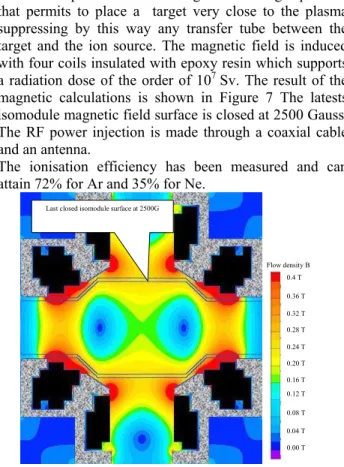
This source presents the advantage to have large apertures that permits to place a target very close to the plasma suppressing by this way any transfer tube between the target and the ion source. The magnetic field is induced with four coils insulated with epoxy resin which supports a radiation dose of the order of 107 Sv. The result of the magnetic calculations is shown in Figure 7 The latests isomodule magnetic field surface is closed at 2500 Gauss. The RF power injection is made through a coaxial cable and an antenna.
The ionisation efficiency has been measured and can attain 72% for Ar and 35% for Ne.
0.4 T 0.36 T 0.32 T 0.16 T 0.24 T 0.20 T 0.28 T 0.12 T 0.08 T 0.04 T 0.00 T Flow density B Last closed isomodule surface at 2500G
0.4 T 0.36 T 0.32 T 0.16 T 0.24 T 0.20 T 0.28 T 0.12 T 0.08 T 0.04 T 0.00 T Flow density B 0.4 T 0.36 T 0.32 T 0.16 T 0.24 T 0.20 T 0.28 T 0.12 T 0.08 T 0.04 T 0.00 T Flow density B Last closed isomodule surface at 2500G
Figure 7: Magnetic field distribution in the monobob ion source
The FEBIAD ion source
The advantage of this kind of source is its small size that minimizes the delay time in the ionization chamber that alllows an access to short life time isotopes and that can be easily heated up to 1800°C. For instance, at ISOLDE- CERN, Switzerland or at IPN Orsay, France, FEBIAD ion sources at high temperature are connected to standard UCx targets and beams of isotopes with half life time lower than 300ms have been measured (for example 124Ag or 94Kr). These prototypes work with an anode grid close to a hot cathode in order to extract the ionizing electrons. The ohmic heating of the cathode is about 1.5 kW and the extraction voltage about 150 V. Outside the vacuum chamber, around the ionization chamber, a magnetic coil is placed in order to optimize the ionization process. The
magnetic field inside the chamber is about 300 Gauss. Furthermore a FEBIAD-kind prototype designed to work efficiently without magnet has been developed and ionization efficiency of about 35% for noble gases. The SPIRAL 2 project raises two issues concerning such a type of ion source. The first one is the life of the source, which should be close to 3 months. The second one deals with the insulator required to apply the discharge high voltage. So far, the life of the MK5 units at ISOLDE-CERN is limited to one month. Under typical on-line conditions, the lifetime is rather twenty days. The main cause of the ionization efficiency collapse is not yet clearly identified.
Thermo-ionic ion source
The surface ion source consists simply of a refractory metal tube at a high temperature. For positive ion productions, the heated tube captures an electron from atoms with low ionization potential impinging on the surface. This ion source is the most efficient for the production of alkali ions. For the other elements, in particular alkali-earth and rare earth, it has been experimentally demonstrated that the ionization efficiency of the surface ion source is enhanced by orders of magnitudes when replacing the simple ionization tube by a hot cavity. The cavity has an extraction hole which area is small compared to the cavity inner surface At that time, only the surface ion source of TRIUMF demonstrated experimentally the possibility of working in conditions close to those foreseen for SPIRAL 2, in term of irradiation time and dose rate.
LASER ion source (Resonance Ionization by
Laser Ion Source)
Different LASER IS have been developed for the production of radioactive ions of non volatile elements. This type of source is particularly efficient for the production of metallic ions. Furthermore, the ionization process is particularly selective.
The LASER IS will not be studied now but the constraints relative to its implantation and use will be taken into account, so as to allow the possibility to inject the laser beam through the low energy beam line and the implementation of a “LASER room” close to the production area.
REFERENCES
1 P. Sortais et al., Rev. Sci. Instrum. 61, p. 228 (1990). 2 P. Lehérissier et al., 9th ICIS conference, Rev. Sci.
Instrum., 73, p 558 (2002)
3 News from GANIL, n°67, p. 11, mars 2001. http://www.ganil.fr/research/sp/ng.html
4 C. Barué et al., PHIBI workshop, Catania, Sept. 2000. 5 L. Maunoury et al, Proceedings of the 18th Int.
Workshop on ECR Ion Sources, February 26-28, College Station, Texas USA (1997)
6 A.C.C. Villari et al Proceedings of. CAARI 2000, Denton, TX, USA (2000)
7 R. Leroy et al, proc. of the 9th ICIS, Rev. of Sci. Instr, 73, p711 (Feb. 2002)
8 M.G. Saint Laurent et al, SPIRAL phase 2, European RTT, final report, www.ganil.fr/ research/developments/spiral2/index.htm
9 LINAG phase 1 report, www.ganil.fr/ research/developments/spiral2/index.htm