Publisher’s version / Version de l'éditeur:
Journal of the Acoustical Society of America, 109, March 3, pp. 999-1010, 2001-03-01
READ THESE TERMS AND CONDITIONS CAREFULLY BEFORE USING THIS WEBSITE.
https://nrc-publications.canada.ca/eng/copyright
Vous avez des questions? Nous pouvons vous aider. Pour communiquer directement avec un auteur, consultez la première page de la revue dans laquelle son article a été publié afin de trouver ses coordonnées. Si vous n’arrivez pas à les repérer, communiquez avec nous à PublicationsArchive-ArchivesPublications@nrc-cnrc.gc.ca.
Questions? Contact the NRC Publications Archive team at
PublicationsArchive-ArchivesPublications@nrc-cnrc.gc.ca. If you wish to email the authors directly, please see the first page of the publication for their contact information.
Archives des publications du CNRC
This publication could be one of several versions: author’s original, accepted manuscript or the publisher’s version. / La version de cette publication peut être l’une des suivantes : la version prépublication de l’auteur, la version acceptée du manuscrit ou la version de l’éditeur.
For the publisher’s version, please access the DOI link below./ Pour consulter la version de l’éditeur, utilisez le lien DOI ci-dessous.
https://doi.org/10.1121/1.1344162
Access and use of this website and the material on it are subject to the Terms and Conditions set forth at
Modeling vibrational energy transmission at bolted junctions between a plate and a stiffening rib
Bosmans, I.; Nightingale, T. R. T.
https://publications-cnrc.canada.ca/fra/droits
L’accès à ce site Web et l’utilisation de son contenu sont assujettis aux conditions présentées dans le site
LISEZ CES CONDITIONS ATTENTIVEMENT AVANT D’UTILISER CE SITE WEB.
NRC Publications Record / Notice d'Archives des publications de CNRC:
https://nrc-publications.canada.ca/eng/view/object/?id=5ea24231-752f-4478-a393-c8e6a11c5d3c https://publications-cnrc.canada.ca/fra/voir/objet/?id=5ea24231-752f-4478-a393-c8e6a11c5d3c
Modeling vibrational energy transmission at bolted junctions between a plate and a stiffening rib
Bosmans, I.; Nightingale, T.R.T.
NRCC-44763
A version of this document is published in / Une version de ce document se trouve dan Journal of the Acoustical Society of America, v. 109, no. 3, March 2001, pp. 999-1009
Modelling Vibrational Energy Transmission at Bolted Junctions between a
Plate and a Stiffening Rib.
Ivan Bosmans and Trevor R.T. Nightingale
National Research Council Canada, Institute for Research in Construction, Acoustics, 1500 Montreal Road, Ottawa, Ontario, K1A 0R6, Canada.
Received:
ABSTRACT
An analytical model is presented for structure-borne sound transmission at a bolted junction in a rib-stiffened plate structure. The model is based on the wave approach for junctions of semi-infinite plates and calculates coupling loss factors required by Statistical Energy Analysis. The stiffening rib is modelled as a plate strip and the junction is represented by an elastic interlayer with a spatially dependent stiffness. Experimental verification is carried out on a series of Plexiglas plate structures with varying rib depth and bolt spacing. A well-defined connection length at the junction was created by inserting thin spacers between the plate and the rib at each bolt. Comparison between numerical and experimental data for this case showed good agreement. Measured results for the bolted junction without spacers, suggested that structure-borne sound transmission could be modelled as a series of connections characterized by an equivalent connection length. This concept is explored further by determining an optimum connection length which gives the best agreement between numerical and experimental data.
I. INTRODUCTION
The application of Statistical Energy Analysis1 (SEA) for predicting the vibro-acoustic response of complex structures requires accurate models for structure-borne sound transmission at junctions between plates and beams. In SEA, coupling loss factors quantify the energy flow between coupled plates and are usually calculated by modelling the interaction of plane waves at a junction of corresponding semi-infinite plates. This wave approach has been developed primarily for line connections between semi-infinite plates and infinite beams. In automotive, aerospace and light-weight building structures, many plate junctions are created using rivets, spot weldings, bolts, screws or nails. These junctions generally behave as line connections as long as the wavelengths in the plate are large compared to the fastener spacing. At high frequencies, the plate and rib surfaces between the fastening points do not move in phase, and the junction acts as an array of local connections rather than as a line connection.
This paper investigates structure-borne sound transmission at a bolted junction between a plate and a rib. This type of junction is commonly applied in walls and floors in light-weight building structures, and a thorough understanding of the dynamic behaviour of these junctions is necessary for studying the effects of flanking transmission. The main objective of this paper is to investigate whether a bolted junction should be modelled by considering an equivalent connection length between the connected elements in the vicinity of each fastener. For this purpose, an analytical calculation model is developed for junctions of semi-infinite plates and plate strips, coupled by an elastic interlayer with spatially varying stiffness.
Calculation models predicting structure-borne sound transmission between plates have been published by several authors and the complexity of the modelled junctions has increased considerably over the last two decades. Structure-borne sound transmission at a variety of plate
and beam junctions has been studied by Cremer et al.2 for the cases of normal and random incidence. Low frequency approximations were derived for the normal incidence bending wave transmission loss at corner, tee and cross junctions. The more complicated case including conversion between bending and in-plane waves has been treated for a corner junction. Apart from rigid connections, Cremer’s work included junctions with elastic interlayers as well as plate/beam junctions.
Kihlman3 derived closed form expressions for bending and in-plane wave transmission at symmetric cross-junctions. The symmetry of the junctions simplified the analysis significantly, since in-plane waves are generated only in the plates perpendicular to the excited plate. More general cases of corner, tee and cross junctions including bending, quasi-longitudinal and transverse waves were solved several years later. Wöhle et al.4,5 modelled a junction of semi-infinite plates rigidly attached to a massless beam. Craven et al.6 and Gibbs et al.7 developed a similar calculation model but their approach used a different formulation of the boundary conditions and included the internal loss of the plate material.
Junctions of elastically connected plates are traditionally modelled by introducing a spring element between the connected plates.2,4,5 This approach has been applied by Craik and Osipov8 when modelling structure-borne sound transmission involving elastically supported walls in buildings. Mees and Vermeir9 used a more sophisticated model and treated the elastic layer as a wave supporting medium.
With respect to the properties of the connected plates, most of the authors adopted thin plate theory to describe the bending response and considered junctions of isotropic plates. McCollum et al.10 used thick plate theory to model bending and in-plane wave transmission at a
corner junction. Bosmans et al.11 developed a model for junctions of thin orthotropic plates and discussed its application in the context of an SEA calculation scheme.
Bending wave transmission between plates connected by a common beam has been investigated by Cremer et al.2 Steel12 applied a more extensive theory to predict flanking transmission in framed buildings. The analysis included all wave types and the description of the dynamic behaviour of the beam allowed for a spring-like deformation of the beam cross-section. Langley et al.13 adopted a ‘wave dynamic stiffness’ approach for modelling vibration transmission at plate/beam junctions. The latter approach is applicable to beams with solid cross-sections and to thin walled beam elements with closed or open cross-cross-sections. Later, Heron14 treated a thin walled beam as an assembly of individual plate strips and modelled their interconnection using a wave line impedance method. A similar plate strip formulation was used by Bosmans et al.15 for predicting structure-borne sound transmission across a line connected stiffening rib in an orthotropic plate. Craik et al.16 applied a plate strip model to predict vibration transmission between the leafs of light-weight walls.
Most of the models published in literature were developed for plates connected along a line. Structure-borne sound transmission between point connected plates has traditionally been modelled using the modal approach in SEA.1 In this approach, coupling loss factors are expressed in terms of point mobility functions. Since this simplified model assumes that each point connection is acting independently, the typical transition from line to point connection with increasing frequency is not included in the theory. Craik et al.16 used the modal approach to model point connections between a beam and two parallel plates. Bosmans and Vermeir17 presented a more complete theory where a point connected plate junction is modelled using an interlayer with a spatially dependent stiffness. The spatial variation is assumed to be periodic and
the plate response is described by a scattered wavefield. Since no simplifying assumptions concerning the interaction between the various connections were introduced, this model is applicable for practically any ratio of the structural wavelength to the point spacing. Heron18 discusses a similar technique to formulate the plate response at a junction of point connected plates. The cross transfer matrix description of each connection incorporates all six degrees-of-freedom, but assumes an infinitely small connection length. The latter assumption may not be appropriate when the size of the connection is comparable to the wavelengths in the plate.
In this paper, the plate strip approach and the point connection theory of Refs. 15 and 17 are combined to model structure-borne sound transmission across a stiffening rib which is attached to a plate using equally spaced bolts. The accuracy of this model is demonstrated by experimental verification for the case where spacers are inserted at each point connection to create a well-defined connection length. Experimental results for the case without spacers is compared to numerical data obtained for a variable width of the connections. By comparing these data, it is shown that the transmission across a bolted stiffening rib can be modelled using an equivalent connection length.
II. CALCULATION MODEL
The calculation model is based on the wave approach for periodic junctions of semi-infinite plates as discussed in Ref. 17. The basic principles of this approach are illustrated in Fig. 1. Consider an incident plane wave, with wavenumber ki and angle of incidence θi, traveling toward
the junction on one of the plates. The periodic boundary condition at the junction, characterized by a spatial period L, causes diffuse reflection and transmission of structure-borne sound waves on the source and receiving plates.17 The forces and displacements at the edges of the coupled
plates are expressed in terms of the unknown amplitudes of the waves in the resulting scattered wavefields. The wave amplitudes are calculated as the solution of a system of equations consisting of equilibrium and continuity conditions at the junction. Structure-borne sound transmission is evaluated by the angle dependent transmission coefficient, which is obtained as the ratio of the intensities carried by the incident and transmitted waves. By integrating the transmission coefficient over all angles of incidence, an angle-averaged result is obtained which may be used to calculate SEA coupling loss factors.1,2
The theory presented in the following paragraphs is developed for plates consisting of a linear elastic, homogeneous and isotropic material. Damping is not included in the calculation model, since it is introduced in the final SEA calculations. Classical thin plate theory is applied to describe the bending wave response and the analysis includes quasi-longitudinal and in-plane transverse waves.
Since the calculation model basically represents an extension to the theory of Ref. 17, only the essential modifications are discussed in this paper. The major difference from the existing model is the introduction of a plate strip at the junction. The model also uses a more complete formulation of the junction eccentricity. These modifications affect the forces and displacements at the junction, as well as the formulation of the boundary conditions. Both aspects are discussed in the following paragraphs.
A. Junction geometry
Fig. 2 shows that the junction is composed of four basic elements: junction beam, semi-infinite plate, plate strip and elastic interlayer. All plate structures are connected to the junction beam. For the junctions considered in this paper, the junction beam does not represent any physical part
of the structure and merely represents a common node for the connected plates. A global coordinate system (x0,y0,z0) is located at the centre of the junction beam. The displacement of the
junction beam is described by three translations (ξb,ηb,ζb) and a rotation around the z0-axis (αzb).
The response of semi-infinite plates and plate strips are expressed in local coordinate systems (xp,yp,zp). Fig. 2 further shows the conventions for the forces (Fxp,Fyp,Fzp) and moment (Mzp) per
unit width acting on the plate edge, as well as for the plate edge displacements (ξp,ηp,ζp,αzp). As
opposed to a semi-infinite plate, a plate strip has an additional boundary parallel to the junction, and is infinitely extended only in the zp-direction. Both plate elements can be coupled directly to
the junction beam, or indirectly using an elastic interlayer. The interlayer is modelled as a spring, and its influence is taken into account by transforming forces and displacements at the plate edge to the corresponding parameters at the edge of the interlayer. Treating the interlayer as a spring is justified as long as the wavelengths in the interlayer material are considerably larger than the interlayer thickness. The spring stiffness for each of the four degrees-of-freedom are calculated as in Ref. 17. In this paper, the bolted connection is modelled by a step-wise variation of the spring stiffness, leading to a periodic boundary condition.
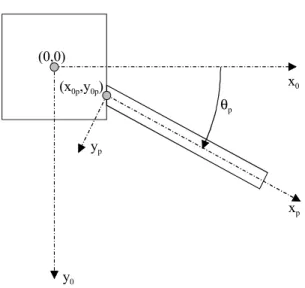
Each plate element can be coupled to the junction at any arbitrary coupling angle θp,
which represents the angle between the (x0,z0)-plane and the (xp,zp)-plane (See Fig. 3). The
fixation point coordinates (x0p,y0p) locate the point in the global coordinate system where the
plate is assumed to be attached to the junction. These coordinates determine the eccentricity by which a plate is mounted at the junction.
The harmonic unit amplitude plane wave traveling toward the junction on the source plate is described by (the time dependence ejωt is omitted in the following equations):
z sin k j x cos k j i i e i i e θ − θ (1)
where x and z refer to the local coordinate system. To satisfy the periodic boundary conditions imposed by a periodic interlayer with spatial period L, the response of the plates is given by a superposition of plane waves traveling away from the junction:17
∑
+ − = θ+ π − − N N n z L n 2 sin k j x k j n i i x e e A (2)where An denotes the wave amplitude. The maximum number of wave components N is
determined based on convergence criteria. An expression for the wave number kx can be derived
by substituting Eq. (2) into the appropriate equations of motion. Substitution of Eq. (2) into the thin plate bending wave equation yields four wavenumbers per wave component n.
In case of a semi-infinite plate, valid wavenumbers are either real and positive, or imaginary and negative. The first set of wavenumbers correspond to waves traveling away from the junction, and the second set to exponentially decaying nearfields. As a result, the general solution for the bending wave response is given as:17
(
)
z L n 2 sin k j N N n x k j n x k j n z L n 2 sin k j N N n pn p i i 2 Bxn 1 Bxn i i e e B e A e ) x ( η ) z , x ( η θ+ π − + − = − − θ+ π − + − =∑
∑
= + = (3)where the wavenumbers kBxn1 and kBxn2 are given in Ref. 17. Since the remaining bending wave
parameters (αzp,Fyp,Mzp) can be expressed in terms of the transverse displacement ηp, they can be
written in a form very similar to Eq. (3). As a result, the x-dependent part corresponding to wave component n for all bending wave parameters, can be written as a function of the unknown bending wave amplitudes An and Bn:
= − − n n x k j x k j 42 n 41 n 32 n 31 n 22 n 21 n 12 n 11 n zpn ypn zpn pn B A e 0 0 e C C C C C C C C ) x ( M ) x ( F ) x ( α ) x ( η 2 Bxn 1 Bxn (4) or: 1 x 2 Bn 2 x 2 Bn 2 x 4 Bn 1 x 4 Bn (x) C E (x)A B = (5)
The coefficient matrix C4Bnx2 is obtained by substitution of Eq. (3) into the formulae of mechanics19. At the plate junction x=0, E2Bnx2(x) becomes a unit matrix and Eq. (5) reduces to:
1 x 2 Bn 2 x 4 Bn 1 x 4 Bn (0) C A B = (6)
In case of a plate strip, a free plate edge is introduced parallel to the junction, at a distance Lx from the coupled plate edge (See Fig. 2). Reflections from the free edge must be
taken into account and the bending wave response of the strip is determined by waves traveling in the positive as well as in the negative x-direction. Consequently, Eq. (4) should be rewritten as: = − − + + + + − − n n n n x k j x k j x k j x k j 44 n 43 n 42 n 41 n 34 n 33 n 32 n 31 n 24 n 23 n 22 n 21 n 14 n 13 n 12 n 11 n zpn ypn zpn pn B A B A e 0 0 0 0 e 0 0 0 0 e 0 0 0 0 e C C C C C C C C C C C C C C C C ) x ( M ) x ( F ) x ( α ) x ( η 2 Bxn 1 Bxn 2 Bxn 1 Bxn (7) or: 1 x 4 Bn 4 x 4 Bn 4 x 4 Bn 1 x 4 Bn (x) C E (x)A B = (8)
The superscripts + and – in Eq. (7) refer to the amplitudes of right and left running waves, respectively. In order to reduce the number of unknowns, it is desirable to eliminate the left running wave amplitudes based on the free boundary condition at x=Lx. At this edge, Fyp and Mzp
are equal to zero, which implies that Fypn(Lx) = Mzpn(Lx) = 0 for every wave component n. By rearranging Eq. (7) for x=Lx, it is possible to express A and −n B , as a function of −n A and +n B : +n
= + + − − n n 22 n 21 n 12 n 11 n n n B A T T T T B A (9)
Using this equation, it is now possible to eliminate the left running wave amplitudes by transforming the coefficient matrix C4Bnx4as follows:
2 x 4 Bn 4 x 4 Bn 2 x 4 Bn C T C = (10)
where the transformation matrix TBn4x2is given as:
T 22 n 12 n 21 n 11 n 2 x 4 Bn T T 1 0 T T 0 1 = T (11)
The forces and displacements at x=0 of a plate strip can be evaluated by substituting C4Bnx2 in Eq. (6). As a result, the boundary conditions of plate strips and semi-infinite plates are described in exactly the same form. Consequently, the elimination of unknowns has improved the computational efficiency, without significantly increasing the complexity of the model. Although the previous analysis was restricted to bending waves, the same procedure can be applied to in-plane waves.
C. Boundary conditions.
The boundary conditions at the junction consist of equilibrium conditions of the junction beam and of continuity conditions between the displacements of the plate edge and the corresponding displacements of the junction beam. The equilibrium conditions are expressed in the global coordinate system, whereas the continuity conditions are formulated in the local coordinate system.
Equilibrium of the junction beam in the x0-direction is described by:
( )
( )
( )
∑
= ∂ ∂ + − p zp p 0 p yp p xp 0 z z , 0 F x θ sin z , 0 F θ cos z , 0 F (12)where the summation is taken over all plates. The third term in Eq. (12) accounts for the additional bending moment applied to the junction beam by the in-plane shear force Fzp. Since
bending of the junction beam is caused by forces acting normal to the beam axis, the influence of the in-plane shear force is taken into account by an equivalent force in the x0-direction. The
equilibrium condition for the remaining degrees-of-freedom are written as:
( )
( )
( )
∑
= ∂ ∂ + + p zp p 0 p yp p xp 0 z z , 0 F y θ cos z , 0 F θ sin z , 0 F (13)( )
∑
= p zp 0,z 0 F (14)( )
(
( )
( )
)
( )
( )
(
F 0,z sinθ F 0,z cosθ)
0 x θ sin z , 0 F θ cos z , 0 F y z , 0 M p p yp p xp p 0 p p yp p xp p 0 p zp = + + − − −∑
∑
∑
(15)As outlined in Ref. 17, the equilibrium conditions are multiplied by e+j(mπ/L)z and integrated over
the spatial period L. By repeating this procedure for m ranging from –N to +N, each equilibrium condition is expressed by 2N+1 equations. Applying this procedure to Eq. (12) yields:
( )
( )
F( )
0 0 m N.. N L πm 2 θ sin k x j θ sin 0 F θ cos 0 F p zpm i i p 0 p ypm p xpm = ∀ =− + + − −∑
(16)Similar expressions can be obtained for Eqs. (13-15).
The continuity conditions of a plate coupled to a periodic elastic interlayer are given by:
( ) ( )
z(
ξ 0,z ξ cosθ η sinθ α(
x sinθ y cosθ)
)
F( )
0,z 0Kx p − b p− b p− zb 0p p− 0p p − xp = (17)
( ) ( )
z(
η 0,z ξ sinθ η cosθ α(
x cosθ y sinθ)
)
F( )
0,z 0( ) ( )
F( )
0,z 0 z η y z ξ x ζ z , 0 ζ z Kz p b 0p b 0p b− zp = ∂ ∂ + ∂ ∂ + − (19)( ) ( )
z(
α 0,z α)
M( )
0,z 0 Krz zp − zb + zp = (20)In these equations, Kx(z), Ky(z), Kz(z) and Krz(z) represent the space dependent, periodically
varying spring stiffness of the elastic interlayer.17 For local connections with a finite width, the spring stiffness is constant over the width of each connection, and zero elsewhere. For idealized point connections, the spring stiffness is expressed in terms of a dirac function. The two partial derivatives in Eq. (19) correspond to the rotation of the junction beam cross-section around the x0- and y0-axes. By applying the same procedure as the one used to derive Eq. (16), each
continuity condition is expressed by 2N+1 equations.17 Application of this procedure to Eq. (17) leads to the following expression:
( )
(
)
(
ξ 0 ξ cosθ η sinθ α x sinθ y cosθ)
LF( )
0 0 m N.. NK xpm N N n p p 0 p p 0 zbn p bn p bn pn xmn − − − − − = ∀ =− +
∑
+ − = (21) An expression for the stiffness coefficient Kxmn is given in Ref. 17. Similar expressions areobtained for Eqs. (18-20). The equilibrium and continuity conditions derived from Eqs. (12-15) and (17-20) are combined with Eq. (6) to create a set of equations in the unknown wave amplitudes. The solution of this set of equations is then used to calculate the intensity carried by the waves transmitted at the junction.
III. EXPERIMENTAL VERIFICATION ON BOLTED JUNCTIONS WITH SPACERS
In this section, the calculation model is validated on a bolted junction between a plate and a stiffening rib (Fig. 4), where thin metal spacers were inserted between both elements to create a well-defined connection length at each fastener. A Plexiglas sheet (2.46 m x 1.24 m x 0.0119 m)
was suspended from the laboratory ceiling using two soft springs. Three different stiffening ribs were attached to the plate using equally spaced bolts. The ribs were mounted in the middle of the sheet and effectively divided the sheet in two identical plates. All ribs had a thickness of 0.0187 m, but were characterized by three different depths Lx: 0.05 m, 0.10 m and 0.235 m. Based on
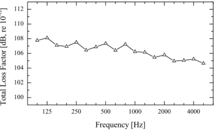
measured resonance frequencies of small beam samples, the elastic properties of Plexiglas were determined as Young’s modulus E = 4.8⋅109 Pa and Poisson’s ratio ν = 0.4, with a density of 1183 kg/m3. The total loss factor of the entire Plexiglas sheet without the ribs was determined using reverberation time measurements. The measured loss factor, shown in Fig. 5, was later introduced as an internal loss factor in the SEA model.
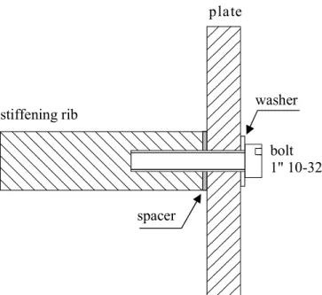
For each depth of the rib, three bolt spacings were considered, as listed in Table I. The bolted junction is illustrated in Fig. 6. At each fastener, a square metal spacer (0.0187 x 0.0187 x 0.0006 m) was inserted between the plate and the rib. The interlayer stiffness corresponding to the metal spacers was calculated using the following literature data: E = 7.1⋅1010 Pa and ν = 0.3.
The bolts were driven in the rib manually using a torque wrench. It was found that increasing the torque above 4.2 Nm did not noticeably affect the measured results. The additional mass introduced at the junction by the bolts, washers and spacers (5.6 g per connection) was not taken into account in the model.
Velocity level difference (VLD) measurements were carried out using a two channel technique as reported by Craik.20 Using this method, the transverse velocity level is measured in one randomly positioned measurement point on each plate while the source plate is excited randomly using a light impact device. The average VLD between the source and the receiving plate is estimated by repeating this procedure for several pairs of measurement points until the average converges to a stable value.
For the calculations, the Plexiglas sheet was modelled as two semi-infinite plates with coupling angles θp = 0° and 180°. For both plates, the fixation point coordinates (x0p,y0p) were
assumed to coincide with the origin of the global coordinate system. The stiffening rib was modelled as a plate strip with coupling angle θp = 90° and fixation point coordinates (0,hp/2),
where hp denotes the thickness of the Plexiglas sheet. The spacers are modelled by a periodic
elastic interlayer connecting the plate strip to the junction beam. The coupling loss factor corresponding to bending wave transmission between both plates was calculated in frequency steps of 1/27 of an octave, and then averaged to obtain one-third-octave band results from 100 to 5000 Hz. The VLD between both plates was estimated using a simple SEA model which consisted of two subsystems corresponding to bending waves on both plates. The rib was not included in the SEA model, since its influence was taken into account when calculating the coupling loss factors.15 Further, in-plane wave subsystems were not considered since their influence is only important for complex structures involving many junctions and long transmission paths.21 Strong coupling effects, which might bias SEA predictions for two nominally identical rectangular plates, are not expected to be important since the modal overlap factors of both bending wave subsystems exceed unity above 160 Hz.
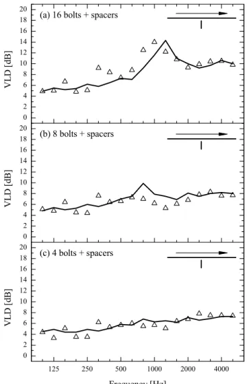
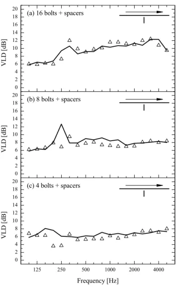
Measured and predicted data for the junction with a 5 cm rib are compared in Fig. 7 for the three cases of point spacing. The measured VLD for the case with 16 connections displays a pronounced peak at 1 kHz. At this frequency, an anti-resonance of the stiffening rib significantly reduces the rotation of the junction, leading to a reduction in bending wave transmission.15 The predicted data also show a maximum in the VLD, but its location is shifted to a higher frequency. The measured results also show a less pronounced maximum at 315 Hz, which is not predicted by the model. These discrepancies might be explained by uncertainties in the measured
material properties, inaccuracies in the modelled boundary conditions of the plate strip or the fact that the inertia due to the fasteners was neglected in the model. Overall, the agreement between theoretical data and measured results is fair since both curves show a similar trend. Good agreement is achieved for the case with 8 connections in Fig. 7b, although the peak predicted at 800 Hz seems to be missing in the measured data. The 4 connection case in Fig. 7c clearly shows the best agreement between measurement and prediction.
Fig. 8 shows the experimental and numerical data for the 10 cm deep rib. The agreement between measurement and calculation is excellent for the case with 16 connections in Fig. 8a. A relatively large prediction error of 6.9 dB can be observed in Fig. 8b at 250 Hz, where the predicted maximum in the VLD does not coincide with the measured maximum at 315 Hz. Also, the calculation model slightly overestimates the VLD in the mid frequency range. For the case with 4 connections in Fig. 8c, the largest discrepancy amounts to 4 dB at 200 Hz, but the agreement above 200 Hz is good.
Finally, the result for the 23.5 cm deep stiffening rib are plotted in Fig. 9. For all cases of point spacing, the model consistently overestimates the VLD below 315 Hz. Above this frequency, the agreement between measurement and calculation is very good for the cases with 16 and 4 bolts (Figs. 9a and 9c). The predictions for the case with 8 bolts in Fig. 9b are very accurate above 1 kHz, but the VLD is slightly overestimated at low and mid frequencies.
Overall, the agreement between measurement and calculation for the three stiffening ribs in Figs. 7-9 is good. The influence of the rib depth and the number of connections is reliably predicted. The calculation model has a tendency to slightly overestimate the VLD, which indicates that the coupling strength between the rib and the plate is overestimated. Nevertheless,
the model has proven to be suitable to predict structure-borne sound transmission at a periodic junction between a plate and a stiffening rib.
IV. EQUIVALENT CONNECTION LENGTH AT BOLTED JUNCTIONS WITHOUT SPACERS
In many realistic junctions using rivets or bolts, the two connected elements are coupled without spacers. Consequently, there will be contact between both elements over the entire length of the junction, even though the actual contact may be discontinuous over time at some locations. Modelling structure-borne sound transmission at these junctions is not as straightforward compared to the case with spacers. In this section, it is shown that junctions without spacers can be treated as an array of local connections characterized by an equivalent connection length. For this purpose, an additional series of experiments was carried out on the Plexiglas structure without spacers for all nine combinations of rib depth and bolt spacing. The equivalent connection length is determined for each junction by fitting numerical data to the measured results.
To understand the behaviour of a bolted junction, it is instructive to review some aspects of bending wave transmission between point connected plates. Co-planar junctions of point connected plates are characterized by a ‘cut-off’ frequency which marks the transition from line connection to point connection.17 The transition frequency depends on the point spacing and the bending wavelength in the plates. When the plate junction involves local connections with a finite coupling length, the width of each connection also has an influence on the bending wave transmission. This is illustrated by the parametric calculation shown in Fig. 10 for the 5 cm deep rib with 4 bolts. By increasing the width of the connections from one that is infinitely small to
one that is equal to the bolt spacing, the junction gradually changes from an idealized point connection to a line connection. Fig. 10 shows that the vibration attenuation increases with increasing connection width. In addition, the transition frequency below which the junction can be considered as a line connection, also increases with increasing coupling length.
The experimental data in Fig. 11a for the 5 cm deep rib illustrate that a junction without spacers shows some distinct features of a point connected plate junction. Structure-borne sound transmission clearly depends on the spacing between the fasteners, even though the rib is nominally in direct contact with the plate. The results for the junctions with 4 and 8 bolts in Fig 11a start to deviate significantly from the result for the 16 bolt case at 500 and 1000 Hz, respectively. In the frequency range where the point spacing does not have a profound influence, the junctions may be considered as line connections. Consequently, 500 Hz and 1000 Hz mark the frequencies above which a transition occurs from line to local connection for the junctions with 4 and 8 bolts. The reduction of the transition frequency with increasing point spacing is typical of point connected plate junctions. When comparing the measured results for the case without spacers (Fig. 11a) to the case with spacers (Fig. 11b), it can be observed that the VLD tends to decrease when spacers are inserted at the junction. Also, the maximum in the VLD for the case with 16 bolts is shifted from 1250 Hz to 1000 Hz as a result of the spacers. Consequently, the spacers have weakened the connection between the plate and the rib.
These observations suggest that a junction without spacers neither behaves as an idealized point connection nor as a line connection, but as something in between. More specifically, the plates appear to be connected by equally spaced connections with (unknown) finite width, and the spacing between the connections is equal to the bolt spacing. Based on the experimental data in Fig. 11, the equivalent connection width seems to be greater than the width
of the spacers. In the following paragraphs, it is shown that structure-borne sound transmission at a bolted junction can be described by assigning an equivalent connection length to each fastener.
The application of the calculation model presented in Section I to the junction without spacers requires two assumptions. The first assumption concerns the linearity of the problem. In between fasteners, the surfaces of the plate and the rib, which are nominally in contact with each other, move apart and together during one cycle of vibration. The discontinuous contact between both elements essentially causes the motion in between two fasteners to be non-linear. Consequently, the application of the theory of Section I requires the assumption that the non-linearity can be ignored and that the transmission at the bolted junction can be described using a linear model.
The second assumption is that the additional damping caused by air pumping can be neglected and that the junction can be treated as a conservative junction. Fortunately, Plexiglas has a relatively high internal damping, and the additional damping due to air pumping, as estimated using the procedure given by Ungar et al.22, generally represents only a small fraction of the internal loss factor. In fact, these small differences would be rather difficult to measure, since the uncertainty of the decay time measurement for the Plexiglas sheet is of the order of 10%. Consequently, the numerical results presented below are based on the same damping data as those used in Section II.
To evaluate the concept of an equivalent connection length, a parametric calculation is carried out with varying width wl of the connections (See Fig. 1). In the absence of the spacers,
the periodic interlayer was rather arbitrarily chosen as a 1 mm thick layer of Plexiglas. For a particular combination of rib depth and bolt spacing, the equivalent connection length, we, is
one-third octave bands. The measured data for the junctions without spacers, together with the results calculated using the equivalent connection lengths are shown in Figs. 12-14. The equivalent connection lengths we are listed in Table II for all combinations of rib depth and bolt
spacing. Also shown in Figs. 12-14 are the results for the extreme cases considered in the parametric calculations: idealized point connection (infinitely small connection length at each bolt) and continuous line connection. The point connection and the line connection correspond to the weakest and the strongest coupling, respectively, between the rib and the plate, and the difference between both cases increases with increasing bolt spacing.
The experimental data and the numerical results corresponding to the equivalent connection length for the 5 cm deep rib are given in Fig. 12. In all three cases, the best agreement between measurement and calculation is obtained when using the equivalent connection length. The measured data for the junction with 16 bolts approaches the results for a line connection, the main difference being a shift in the peak of the VLD. The junction with 8 bolts clearly represents an intermediate case between a line and a point connection. Fig. 12c demonstrates that the junction with 4 bolts can be modelled in first approximation by a point connection, although the latter approach leads to a systematic underestimation of the VLD.
Good agreement is also achieved when using the equivalent connection length for the 10 cm deep stiffening rib, as illustrated in Fig. 13. When excluding the large discrepancy around 315 Hz in Fig. 13a, the rms prediction error is less than 1.5 dB for all cases of bolt spacing. The predictions using a line connection are very accurate for the junction with 16 bolts, and work equally well for the case with 8 bolts below 4 kHz. The junction with 4 bolts represents an intermediate case, as the measured VLD lies between those of the line and point connections.
The calculations using the idealized point connections consistently underestimate the VLD above 250 Hz for all cases of bolt spacing.
The comparison between measured and calculated data for the 23.5 cm rib in Fig. 14, reveals an overestimation of the VLD when using the equivalent connection length at low frequencies. A similar overestimation was observed for the junction with spacers in Fig. 9. Further, the measured VLD at high frequencies for the junction with 16 bolts in Fig. 14a is higher than predicted using a line connection. As a result, good agreement could only be achieved below 2 kHz. Above 250 Hz, the concept of an equivalent connection length seems to work well for the remaining cases in Figs. 14b and 14c. The predictions using a line connection are reasonably accurate for the cases with 16 and 8 bolts. The point connection model underestimates the VLD above 500 Hz for all cases of bolt spacing.
Table II presents the equivalent connection lengths for the 9 cases. The data indicate that the equivalent connection length increases with increasing bolt spacing. However, the table also shows that an increase in we does not necessarily correspond to an increase in the ratio we/L. In
most cases, this ratio actually decreases with increasing bolt spacing. Unfortunately, the sensitivity of the equivalent connection length to the rib depth does not show a clear trend. This may be caused by the fact that the calculation model has a limited accuracy and is based on a number of simplifying assumptions. Consequently, inaccuracies of the model might influence the estimate of the equivalent connection length which is determined by minimizing the prediction error. As a result, there may not be a clear relationship between the equivalent length and the physical properties of the junction.
Overall, the results in Figs. 12-14 illustrate that an appropriate choice of the connection width yields calculated data which agree well with measured results. Although the equivalent
connection length was assumed to be frequency independent, the calculated data matched the measured results in most of the frequency range. Consequently, it was demonstrated that a bolted plate/rib junction can be modelled by assigning an equivalent connection length to each fastener. It should be stressed that the equivalent connection length does not represent a physical parameter, since the detailed behaviour of the junction in reality is much more complex. The results of this paper merely show that a structure-borne sound transmission model, which incorporates the periodic boundary condition of a bolted junction, can be improved if a finite connection length is assigned to the fasteners.
V. CONCLUSIONS
Structure-borne sound transmission at a bolted junction between a plate and a stiffening rib is investigated theoretically and experimentally. A calculation model was presented where the rib was modelled as an infinite plate strip and the bolted connection was treated as an elastic interlayer with periodically varying elastic properties. The model was verified experimentally on a Plexiglas structure where thin metal spacers were inserted between the plate and the rib. Several combinations of the rib depth and bolt spacing were considered and good agreement was achieved between measured and calculated data. Experimental results on a similar structure without spacers demonstrated that the bolted junction behaves as a series of local connections. By comparing measured data to the results of a parametric calculation, an equivalent connection length was determined for each bolt. Measured and calculated results showed good agreement, which confirmed that a bolted junction between a plate and a rib can be modelled using an equivalent connection length. Unfortunately, a clear relationship between the equivalent
connection length and the physical properties of the junction could not be identified. This is suggested for future work.
REFERENCES 1
R.H. Lyon and R.G. DeJong, Theory and Application of Statistical Energy Analysis. (Butterworth-Heinemann, Boston, second edition, 1995).
2
L. Cremer, M. Heckl and E.E. Ungar, Structure-borne sound. (Springer-Verlag, Berlin, 1988).
3
T. Kihlman, Transmission of structure-borne sound through buildings. (Report 9, National Swedish Institute for Building Research, Stockholm, 1967).
4
W. Wöhle, Th. Beckmann and H. Schreckenbach, “Coupling loss factors for statistical energy analysis of sound transmission at rectangular structural slab joints, part I,” J. Sound Vib. 77(3), 323-334 (1981).
5
W. Wöhle, Th. Beckmann and H. Schreckenbach, “Coupling loss factors for statistical energy analysis of sound transmission at rectangular structural slab joints, part II,” J. Sound Vib.
77(3), 335-344 (1981). 6
P.G. Craven and B.M. Gibbs, “Sound transmission and mode coupling at junctions of thin plates, part I : representation of the problem,” J. Sound Vib. 77(3), 417-427 (1981).
7
B.M. Gibbs and P.G. Craven, “Sound transmission and mode coupling at junctions of thin plates, part II : parametric survey,” J. Sound Vib. 77(3), 429-435 (1981).
8
R.J.M. Craik and A. Osipov, “Structural isolation of walls using elastic interlayers,” Appl. Acoust. 46, 233-249 (1995).
9
P. Mees and G. Vermeir, “Structure-borne sound transmission at elastically connected plates,” J. Sound Vib. 166(1), 55-76 (1993).
10
M.D. McCollum and J.M. Cuschieri, “Bending and in-plane wave transmission in thick connected plates using statistical energy analysis,” J. Acoust. Soc. Am. 88(3), 1480-1485 (1990).
11
I. Bosmans, P. Mees and G. Vermeir, “Structure-borne sound transmission between thin orthotropic plates: analytical solutions,” J. Sound Vib. 191(1), 75-90 (1996).
12
J.A. Steel, “Sound transmission between plates in framed structures,” J. Sound Vib. 178(3), 379-394 (1994).
13
R.S. Langley and K.H. Heron, “Elastic wave transmission through plate/beam junctions,” J. Sound Vib, 143(2), 241-253 (1990).
14
K.H. Heron, “Predictive SEA using line wave impedances,” In: F.J. Fahy and W.G. Price (Eds.) IUTAM Symposium on Statistical Energy Analysis, 107-119. (Kluwer, Dordrecht, 1999).
15
I. Bosmans and T.R.T. Nightingale, “Structure-borne sound transmission in rib-stiffened plate structures typical of wood frame buildings,” Build. Acoust., 6(3/4), 289-308 (1999).
16
R.J.M. Craik and R.S. Smith, “Sound transmission through lightweight parallel plates. Part II: structure-borne sound,” Appl. Acoust. 61, 247-269 (2000).
17
I. Bosmans and G. Vermeir, “Diffuse transmission of structure-borne sound at periodic junctions of semi-infinite plates,” J. Acoust. Soc. Am. 101(6), 3443-3456 (1997).
18
K.H. Heron, “The wave approach to predictive Statistical Energy Analysis and equally spaced point connections with isolators,” Proceedings NOISE-CON 98, 579-584 (1998).
19
W. Weaver, S.P. Timoshenko and D.H. Young, Vibration problems in engineering. (Wiley, New York, fifth edition, 1990).
20
R.J.M. Craik, “The measurement of structure-borne sound transmission using impulsive sources,” Appl. Acoust. 15, 355-361 (1982).
21
R. Lyon, “In-plane contribution to structural noise transmission,” Noise Control Eng. J. 26(1), 22-27 (1986).
22
E.E. Ungar and J.R. Carbonell, “On panel vibration damping due to structural joints,” J. Acoust. Soc. Am. 4(8), 1385-1390 (1966).
TABLES
Number of bolts Bolt spacing L [m]
Distance of first bolt from rib end at z=0 [m]
16 0.078 0.039
8 0.156 0.117
4 0.312 0.195
TABLE I. Bolt spacing and location of first bolt, for the junctions with 16, 8 and 4 equally
Equivalent connection length we[m] (we/L)
Rib depth Lx [m] 16 bolts 8 bolts 4 bolts
0.05 0.0390 (0.50) 0.0562 (0.36) 0.1186 (0.38)
0.10 0.0421 (0.54) 0.0967 (0.62) 0.1560 (0.50)
0.235 0.0546 (0.70) 0.0905 (0.58) 0.1310 (0.42)
TABLE II. Equivalent connection length we, and the ratio of the connection length to the bolt
FIGURE CAPTIONS
FIG. 1. An incident plane wave, with wavenumber ki and angle of incidence θi , causes scattered
wave fields on the periodically connected plates. The junction is modelled using a periodic elastic interlayer characterized by a thickness hl, connection width wl and spatial period L.
FIG. 2. Conventions for forces and displacements at the junction. An arbitrary junction is modelled using a combination of four basic elements: a junction beam, a semi-finite plate or infinite plate strip and an elastic layer.
FIG. 3. The plate orientation and position in the global coordinate system (x0,y0,z0) is determined
by the coupling angle θp, and the fixation point coordinates (x0p,y0p).
FIG. 4. Experiments were carried out on a Plexiglas sheet suspended from the laboratory ceiling using two soft springs. The stiffening ribs were attached using equally spaced bolts. Thin metal spacers were inserted between the plate and the rib at each bolt.
FIG. 5. Measured total loss factor of the Plexiglas sheet without ribs as a function of frequency. FIG. 6. Detail of the bolted junction between the plate and the rib.
FIG. 7. Comparison between measured and predicted VLD for the 5 cm deep rib with spacers for three different numbers of bolts. Measurement (∆), prediction ().
FIG. 8. Comparison between measured and predicted VLD for the 10 cm deep rib with spacers for three different numbers of bolts. Measurement (∆), prediction ().
FIG. 9. Comparison between measured and predicted VLD for the 23.5 cm deep rib with spacers for three different numbers of bolts. Measurement (∆), prediction ().
FIG. 10. Calculated VLD’s for the 5 cm deep beam with 4 connections with variable width. The arrow indicates the trend of the results when increasing the width of the connections.
FIG.11. Measured VLD for the 5 cm deep rib without (a) and with (b) spacers for different numbers of bolts: 16 (9), 8 (±) and 4 (∆) bolts.
FIG. 12. Comparison between measured and predicted VLD for the 5 cm deep rib without spacers for three different numbers of bolts. Measurement (∆), calculation: equivalent connection length (), line connection (– – – –), point connection (⋅⋅⋅⋅⋅).
FIG. 13. Comparison between measured and predicted VLD for the 10 cm deep rib without spacers for three different numbers of bolts. Measurement (∆), calculation: equivalent connection length (), line connection (– – – –), point connection (⋅⋅⋅⋅⋅).
FIG. 14. Comparison between measured and predicted VLD for the 23.5 cm deep rib without spacers for three different numbers of bolts. Measurement (∆), calculation: equivalent connection length (), line connection (– – – –), point connection (⋅⋅⋅⋅⋅).
ki θi
L wl
hl
FIG. 1. An incident plane wave, with wavenumber ki and angle of incidence θi , causes scattered
wave fields on the periodically connected plates. The junction is modelled using a periodic elastic interlayer characterized by a thickness hl, connection width wl and spatial period L.
xp yp zp Fxp Mzp αzp ηp ξp αzb ηb semi-infinite plate junction beam plate strip x0 y0 z0 elastic interlayer Lx ξb ζb Fyp Fzp ζp
FIG. 2. Conventions for forces and displacements at the junction. An arbitrary junction is modelled using a combination of four basic elements: a junction beam, a semi-finite plate or infinite plate strip and an elastic layer.
x0 y0 yp x p (x0p,y0p) θp (0,0)
FIG. 3. The plate orientation and position in the global coordinate system (x0,y0,z0) is determined
FIG. 4. Experiments were carried out on a Plexiglas sheet suspended from the laboratory ceiling using two soft springs. The stiffening ribs were attached using equally spaced bolts. Thin metal spacers were inserted between the plate and the rib at each bolt.
125 250 500 1000 2000 4000 100 102 104 106 108 110 112 T o tal L o ss F acto r [ d B , r e 1 0 -1 2 ] Frequency [Hz]
plate stiffening rib spacer washer bolt 1" 10-32
0 2 4 6 8 10 12 14 16 18 20
(a) 16 bolts + spacers
VL D [ d B] 0 2 4 6 8 10 12 14 16 18 20 (b) 8 bolts + spacers VLD [ d B ] 125 250 500 1000 2000 4000 0 2 4 6 8 10 12 14 16 18 20 (c) 4 bolts + spacers VLD [ d B ] Frequency [Hz]
FIG. 7. Comparison between measured and predicted VLD for the 5 cm deep rib with spacers for three different numbers of bolts. Measurement (∆), prediction ().
0 2 4 6 8 10 12 14 16 18 20
(a) 16 bolts + spacers
VL D [ d B] 0 2 4 6 8 10 12 14 16 18 20 (b) 8 bolts + spacers VLD [ d B ] 125 250 500 1000 2000 4000 0 2 4 6 8 10 12 14 16 18 20 (c) 4 bolts + spacers VLD [ d B ] Frequency [Hz]
FIG. 8. Comparison between measured and predicted VLD for the 10 cm deep rib with spacers for three different numbers of bolts. Measurement (∆), prediction ().
0 2 4 6 8 10 12 14 16 18 20
(a) 16 bolts + spacers
VL D [ d B] 0 2 4 6 8 10 12 14 16 18 20 (b) 8 bolts + spacers VLD [ d B ] 125 250 500 1000 2000 4000 0 2 4 6 8 10 12 14 16 18 20 (c) 4 bolts + spacers VLD [ d B ] Frequency [Hz]
FIG. 9. Comparison between measured and predicted VLD for the 23.5 cm deep rib with spacers for three different numbers of bolts. Measurement (∆), prediction ().
125 250 500 1000 2000 4000 0 2 4 6 8 10 12 14 16 18 20 line connection point connection VLD [ d B ] Frequency [Hz]
FIG. 10. Calculated VLD’s for the 5 cm deep beam with 4 connections with variable width. The arrow indicates the trend of the results when increasing the width of the connections.
0 2 4 6 8 10 12 14 16 18 20
(a) without spacers
VLD [ d B ] 125 250 500 1000 2000 4000 0 2 4 6 8 10 12 14 16 18 20 (b) with spacers VLD [ d B ] Frequency [Hz]
FIG. 11. Measured VLD for the 5 cm deep rib without (a) and with (b) spacers for different numbers of bolts: 16 (9), 8 (±) and 4 (∆) bolts.
0 2 4 6 8 10 12 14 16 18 20 (a) 16 bolts VL D [ d B] 0 2 4 6 8 10 12 14 16 18 20 (b) 8 bolts VL D [ d B ] 125 250 500 1000 2000 4000 0 2 4 6 8 10 12 14 16 18 20 (c) 4 bolts VL D [ d B] Frequency [Hz]
FIG. 12. Comparison between measured and predicted VLD for the 5 cm deep rib without spacers for three different numbers of bolts. Measurement (∆), calculation: equivalent connection length (), line connection (– – – –), point connection (⋅⋅⋅⋅⋅).
0 2 4 6 8 10 12 14 16 18 20 (a) 16 bolts VL D [ d B] 0 2 4 6 8 10 12 14 16 18 20 (b) 8 bolts VL D [ d B ] 125 250 500 1000 2000 4000 0 2 4 6 8 10 12 14 16 18 20 (c) 4 bolts VL D [ d B] Frequency [Hz]
FIG. 13. Comparison between measured and predicted VLD for the 10 cm deep rib without spacers for three different numbers of bolts. Measurement (∆), calculation: equivalent connection length (), line connection (– – – –), point connection (⋅⋅⋅⋅⋅).
0 2 4 6 8 10 12 14 16 18 20 (a) 16 bolts VL D [ d B] 0 2 4 6 8 10 12 14 16 18 20 (b) 8 bolts VL D [ d B ] 125 250 500 1000 2000 4000 0 2 4 6 8 10 12 14 16 18 20 (c) 4 bolts VL D [ d B] Frequency [Hz]
FIG. 14. Comparison between measured and predicted VLD for the 23.5 cm deep rib without spacers for three different numbers of bolts. Measurement (∆), calculation: equivalent connection length (), line connection (– – – –), point connection (⋅⋅⋅⋅⋅).