Publisher’s version / Version de l'éditeur:
Vous avez des questions? Nous pouvons vous aider. Pour communiquer directement avec un auteur, consultez la première page de la revue dans laquelle son article a été publié afin de trouver ses coordonnées. Si vous n’arrivez pas à les repérer, communiquez avec nous à PublicationsArchive-ArchivesPublications@nrc-cnrc.gc.ca. Questions? Contact the NRC Publications Archive team at
PublicationsArchive-ArchivesPublications@nrc-cnrc.gc.ca. If you wish to email the authors directly, please see the first page of the publication for their contact information.
https://publications-cnrc.canada.ca/fra/droits
L’accès à ce site Web et l’utilisation de son contenu sont assujettis aux conditions présentées dans le site LISEZ CES CONDITIONS ATTENTIVEMENT AVANT D’UTILISER CE SITE WEB.
Propellers/Shafting 2006 Symposium 2006 [Proceedings], 2006
READ THESE TERMS AND CONDITIONS CAREFULLY BEFORE USING THIS WEBSITE. https://nrc-publications.canada.ca/eng/copyright
NRC Publications Archive Record / Notice des Archives des publications du CNRC :
https://nrc-publications.canada.ca/eng/view/object/?id=8f210b1f-4004-43e4-9fa7-1c56345b6e29 https://publications-cnrc.canada.ca/fra/voir/objet/?id=8f210b1f-4004-43e4-9fa7-1c56345b6e29
NRC Publications Archive
Archives des publications du CNRC
This publication could be one of several versions: author’s original, accepted manuscript or the publisher’s version. / La version de cette publication peut être l’une des suivantes : la version prépublication de l’auteur, la version acceptée du manuscrit ou la version de l’éditeur.
Access and use of this website and the material on it are subject to the Terms and Conditions set forth at
Study of puller podded propulsors with tapered hub propellers in
straight course and azimuthing conditions
National Research Council Canada Institute for Ocean Technology Conseil national de recherches Canada Institut des technologies oc ´eaniques
Institute Report
IR-2006-34
Study of puller podded propulsors with tapered hub
propellers in straight course and azimuthing conditions
Islam, M.F., Veitch, B., Bose, N., Liu, P.
September 2006
Islam, M., Veitch, B., Bose, N., Liu, P. 2006. Study of puller podded propulsors with tapered hub propellers in straight course and azimuthing conditions. Propellers/Shafting 2006 Symposium, 12-13 September, 2006, Williamsburg, Virginia. : 10-1 - 10-14. Pre-print version.
Hydrodynamic Characteristics of Puller Podded Propulsors
with Tapered Hub Propellers
Mohammed Fakhrul Islam
Faculty of Engineering and Applied Science, Memorial University of Newfoundland
St. John’s, NL, A1B 3X5, Canada
Brian Veitch
Faculty of Engineering and Applied Science, Memorial University of Newfoundland
St. John’s, NL, A1B 3X5, Canada
Neil Bose
Faculty of Engineering and Applied Science, Memorial University of Newfoundland
St. John’s, NL, A1B 3X5, Canada
Pengfei Liu
Institute for Ocean Technology, National Research Council Canada
St. John’s, NL, A1B 3T5, Canada
ABSTRACT
This paper presents the results of an experimental study on the effects of propeller hub angle and azimuth conditions on the propulsive characteristics of puller podded propulsors in open water conditions. The propulsive performance of two model puller-podded units with different hub geometry was measured using a custom designed pod dynamometer in a towing tank. The podded units were tested to measure the thrust and torque of the propeller and the forces on the whole unit in three orthogonal directions. The tests were conducted for a range of advance coefficients of 0 to 1.2, combined with the range of static azimuth angles from +20° to –20° with a 10° increment. The dynamometer system consisted of a six-component global dynamometer and a three-component pod dynamometer. The variation in the propulsive performance because of the changes in hub geometry was examined first, followed by a study on the effect of azimuth conditions on the forces and moments on the propulsor. The results of the measurements are presented as the changes of forces and moments of the podded unit on the basis of advance coefficients and azimuth angles. The results illustrated that for the range of azimuth angles tested, the thrust and torque of the propeller and the forces on the whole unit in three orthogonal directions are complex functions of the azimuth angles for puller propulsors.
1. INTRODUCTION
Podded propulsors have become a popular main propulsion system for ships due to their better hydrodynamic characteristics than the conventional propeller-rudder system and the advantages of diesel-electric propulsion. This propulsion unit is considered as a very useful combination of propulsion and steering system. It is accepted that a podded propulsor allows more flexibility in design of the internal arrangement of a ship, potentially reduced noise and vibration, and increased manoeuvrability, especially in a confined space Pakaste et al. (1999).
A research program on podded propellers is being undertaken jointly by the Ocean Engineering Research Centre (OERC) at Memorial University of Newfoundland (MUN), the National Research Council’s Institute for Ocean Technology (IOT), Oceanic Consulting Corporation, and Thordon Bearings Ltd. The program combines parallel developments in numerical prediction methods and experimental evaluation. Amongst the hydrodynamic issues that have been identified are questions regarding the effects of hub taper angle (Islam (2004), Islam et al. (2004), Islam
et al. (2005), Islam et al. (2006), Taylor et al. (2005), Taylor (2005)), pod-strut configuration (Islam (2004), Taylor (2005)), pod-strut interactions (He et al. (2005) and He et al. (2005)), gap pressure (MacNeill et al. 2004), and pod-strut geometry (Molloy et al. (2005) and Islam (2004)) on podded propeller performance. The present study focuses on the effect of propeller hub geometry and azimuth conditions of puller-podded propulsor performance.
Szantyr (2001a and 2001b) published one of the first sets of systematic experimental data on podded propulsors as the main propulsion unit with static azimuth angles. The tests measured the axial and transverse loads and used traditional non-dimensional coefficients to analyze the data. The study was limited to ±15° azimuth angles. In the work, the effect of an azimuth angle on propeller torque was not studied. Grygorowicz and Szantyr (2004) presented open-water measurements of podded propulsors both in puller and pusher configurations in a circulating water channel. Heinke (2004) reported systematic model test results with a 4- and 5-bladed propeller fitted to a generic pod housing in pull- and push-mode. In the report, Heinke presented systematic data for forces and moments on the propeller and pod body at different static azimuth angles. Stettler et al. (2004) also investigated the dynamics of azimuth podded propulsor forces with emphasis on the application of nonlinear vehicle manoeuvring dynamics. There still exists considerable deficiency in the understanding of the hydrodynamic behavior of propellers and pods under different azimuth operating conditions.
The study on the hub geometry and azimuth conditions was aimed to help the better understanding of the behavior of forces and moments that act on the pods, which is important to design the propulsor. For instance, the study would quantify the relationship between azimuth conditions and bearing loads. In a study of podded propulsor failures, bearing failure was identified as one of the most significant cause of failure of the propulsors, Carlton (2002). This study would help the bearing designer to design pod bearings based on the loads that act on the propulsor at different azimuth conditions. Section 2 details the geometry of the propeller and pod-strut models used in this study, while section 3 presents a brief description of the apparatus and testing techniques used. Experimental results and discussions are provided in section 4, followed by summarizing conclusions in section 5.
2. EXPERIMENTAL SET-UP 2-1. Pod Models
The experiments included tests on two model propellers with two pods. The two propellers had identical blade section geometry but different hub taper angles of 15° and 20° (namely, Pull-15° and Pull-20°, respectively). The propellers were four bladed with a diameter of 0.27m, pitch-diameter ration (P/D) of 1.0 and expand area ration (EAR) of 0.6. The geometric particulars of the propellers are given in Islam (2004). The taper angles of the conical hubs were varied to study the influence of the taper angle on the performance of the propulsors.
The geometric particulars of the pod-strut models were defined using the parameters depicted in Figure 1. The values for the model propulsors were selected to provide an average representation of in-service, full-scale single screw podded propulsors. The particulars of the two pod-strut bodies tested are shown in Table 1. As the propeller hub taper angle was the only factor being considered in the first part of the study, only the fore taper angle was varied in the two pod-strut bodies. This was done to ensure a smooth flow transition between the propeller and the pod-strut body. Since all remaining parameters were held constant, Pod 1 with a 15° fore taper angle was used in combination with the Pull-15° propeller, and Pod 2 with a 20° fore taper angle was used in combination with the Pull-20° Propeller. For the study of performance in azimuth conditions, only Pod 2 was tested.
Table 1. Geometric particulars of the two pod-strut models.
2-2. Experimental Apparatus and Approach
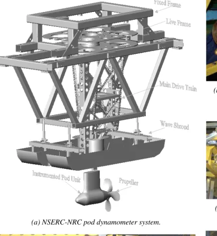
The open water tests of the two pods in straight course and azimuth conditions were performed in accordance with the ITTC recommended procedure, Podded Propulsor Tests and Extrapolation, 7.5-02-03-01.3 (2002), and the description provided by Mewis (2001). A custom-designed dynamometer system called the NSERC-NRC pod dynamometer system (MacNeill et
al. 2004) was used to measure propeller thrust, torque,
and unit forces and moments. In the instrumentation, a motor fitted above the propeller boat drove the propeller via a belt system. The center of the propeller
shaft was 1.5DProp (propeller diameter) below the water
surface. A boat shaped body called wave shroud was attached to the frame of the test equipment and placed just above the water surface. The boat stayed 3 to 5 mm above the water surface to avoid waves caused by the strut piercing the surface. The part of the shaft above the strut (the shaft connected the pod unit to the main drive of the equipment) went through the boat. Also, water temperature, carriage speed, V, and the rotational
speed of the propeller, n, were measured. Figure 2
shows the different parts of the experimental apparatus.
External Dimensions of Model Pods Pod 1 mm Pod 2 mm
Propeller Diameter, DProp 270 270
Pod Diameter, DPod 139 139
Pod Length, LPod 410 410
Strut Height, SHeight 300 300
Strut Chord Length 225 225
Strut Distance, SDist 100 100
Strut Width 60 60
Fore Taper Length 85 85
Fore Taper Angle 15° 20°
Aft Taper Length 110 110
Aft Taper Angle 25° 25°
As shown in Figure 2(a), the dynamometer system has two major parts. The first part is the pod dynamometer, which measures the thrust and torque of the propeller at the propeller shaft. The second part of the system is the global dynamometer, which measures the unit forces in three coordinate directions at a location above the propeller boat. A propeller boat was designed to minimize the surface wave effects. Further details of the experimental apparatus can be found in MacNeill et
al. (2004). The propulsor was placed at different static
azimuth conditions by rotating the entire lower part of the instrumentation (instrumented pod unit and the main drive as shown in Figure 2(a)). The entire lower part hung on a round plate, which had machined marks that defined the azimuth angles.
Fig. 1- Geometric parameters used to define pod-strut geometry.
(b) Propeller and the pod encasing the pod
dynamometer
(a) NSERC-NRC pod dynamometer system.
(c) Global dynamometer looking from below.
(e) Motor that runs the propeller with the gearbox. (d) Motor used in the lifting system. Fig. 2- Different parts of the experimental apparatus used in the pod series tests.
3. RESULTS AND DISCUSSIONS
The NSERC-NRC pod dynamometer system can measure propeller and pod forces and moments,
namely: propeller thrust at hub end (Tprop), propeller
thrust at pod end (Tpod), propeller torque (Q), unit
longitudinal force (FX) and moment (MX), unit
transverse force (FY) and moment (MY), and unit vertical
force (FZ) and moment (MZ).
For the study of hub taper angle, the measurements were done in straight course and in puller configurations using the two pods (Pod 1 and Pod 2).
For the study of azimuth conditions, the measurements were done in puller configurations using the Pod 2 at five different azimuth angles. The global dynamometer was calibrated using the method as described in David
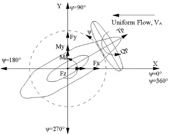
et al. (1980) and Galway (2000). The methods take into account cross talk between the six load cells and produced an interaction matrix to convert the voltage output into relevant forces and moments. The definition of the forces, moments and co-ordinates that were used to analyze the data and present the results is shown in Figure 3. The coordinate centre coincided with the
intersection of the horizontal axis through the propeller shaft centre and the vertical axis through the strut shaft center. The results are presented in the form of traditional non-dimensional coefficients as defined in Table 2.
Figure 3. Definitions of forces, moments, co-ordinates of a puller azimuth podded propulsor.
Table 2. List of performance coefficients for the podded propulsor unit.
Performance Characteristics Data Reduction Equation
KTprop – propeller thrust coefficient
T
/
n
2D
4prop
ρ
KTunit– unit thrust coefficient, KTx
or Longitudinal force coefficient, KFX
4 2
/
n
D
T
unitρ
orF
X/
ρ
n
2D
410KQ – propeller torque coefficient
10
Q
/
ρ
n
2D
5J – propeller advance coefficient
V
nD
A
/
ηprop – propeller efficiency
(
)
Q Tprop
K
K
J
/
2
π
×
/
ηunit – unit efficiency
(
)
Q Tunit
K
K
J
/
2
π
×
/
KFy – transverse force coefficient
F
/
n
2D
4Y
ρ
KFz– vertical force coefficient
F
/
n
2D
4Z
ρ
KMx– moment coefficient around x axis
M
/
n
2D
5X
ρ
KMy– moment coefficient around y axis
M
/
n
2D
5Y
ρ
KMz– moment coefficient around z axis
(steering moment) 5 2
/
n
D
M
Zρ
Where,Tprop - propeller thrust ρ – water density
Tunit - unit thrust n – propeller rotational speed
Q - propeller torque D – propeller diameter
VA - propeller advance speed F X, Y, Z - components of the hydrodynamic force on the
pod
M X, Y, Z - components of the hydrodynamic moment on
the pod
3-1. Influence of Hub Taper Angle
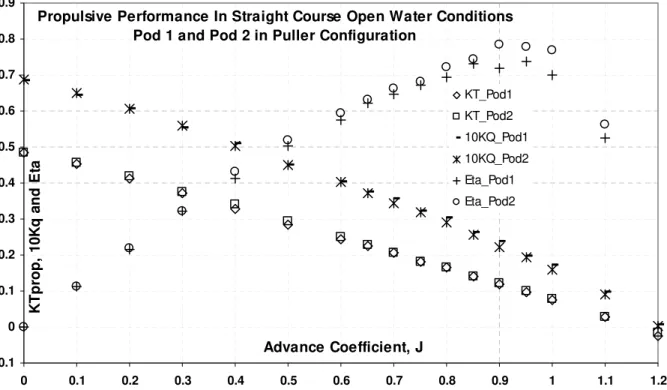
The KTprop, KTunit, 10KQ, ŋpropand ŋunitvalues for the two
pods in straight course operating conditions (in the
range of J=0.0~1.20) is presented in Figures 4 and 5. The experiments were conducted in the puller configuration at 17 different advance coefficients with repetition of at least 4 advance coefficients. The plot
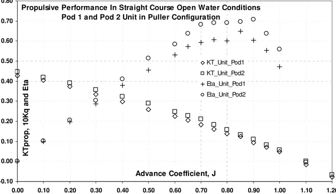
shown in the figure provides a comparison of the open water results for the two pods. Figure 4 shows the thrust and torque coefficients and propulsive efficiencies of only the propellers, propeller with 15° taper angle and propeller with 20° taper angle, in the two pod units, Pod 1 and Pod 2, respectively. Figure 5 shows the thrust coefficients and propulsive efficiencies of the two pod units (pod-strut-propeller as a whole unit) Pod 1 and Pod 2. All the measurements were conducted at a constant 660 rpm both for the positive direction of rotation, Pull-20° (i.e. clockwise rotation viewed from downstream) and negative direction of rotation, Pull-15° (i.e. anticlockwise rotation viewed from downstream). The analysis of the repeated tests showed that the repeatability for the thrust and torque coefficients stayed within 2%. Taylor (2005) presented an uncertainly analysis of the test equipment.
To assess the influence of the hub taper angle on the podded propeller units, the differences in performance coefficients of the two pods are shown in Table 3. The percent values were calculated using equation 1.
(
2 1)
100
/
2 0.0%
=
−
×
= J pod pod podX
X
X
Diff
…(1)From Figures 4 and 5, and Table 3, it is observed that for two podded units in puller configurations, increasing the hub taper angle had noticeable effect on propeller thrust and torque coefficient and efficiency in
the range of advance coefficients tested. Increasing hub taper angle had an increasing effect on thrust coefficient as the advance coefficient was increased from 0.0 to 0.5. However, the thrust was decreased for the propeller with increasing hub angle as the advance coefficient was above 0.6. The Pull-20° propeller produced 2% more and 01% less thrust than the Pull-15° propeller at advance coefficient of 0.5 and 0.8, respectively. The propeller shaft torque coefficient was increased by a small amount (within 0.3%) in the range of advance coefficient of 0.0 to 0.6, as the hub angle was increased. The propeller shaft torque coefficient decreased approximately 2.0% as the hub angle was increased (when the advance coefficients were above 0.6). This resulted in noticeable increase in propeller efficiency
with an increase in hub angle (4.0% increase in ŋpropat
J=0.8). However, Pull-20° produced higher unit thrust
at all advance coefficients, and the maximum increase was seen at moderate advance coefficients of J=0.5~0.8 (approximately 5% increase at J=0.8). Similarly to the propeller efficiency or the unit thrust coefficient, the pod unit with a higher hub angle provided higher unit efficiency. Also, the maximum increase of unit efficiency for the propeller with a higher hub angle was seen at the advance coefficient of J=0.8 (approximately 13.0%).
Propulsive Performance In Straight Course Open Water Conditions Pod 1 and Pod 2 in Puller Configuration
-0.1 0 0.1 0.2 0.3 0.4 0.5 0.6 0.7 0.8 0.9 0 0.1 0.2 0.3 0.4 0.5 0.6 0.7 0.8 0.9 1 1.1 1.2 Advance Coefficient, J K Tpr op, 1 0 K q a nd E ta KT_Pod1 KT_Pod2 10KQ_Pod1 10KQ_Pod2 Eta_Pod1 Eta_Pod2
Fig. 4- Propulsive performance of the propeller “only” for the propulsors, Pod 1 (propeller with 15° hub) and Pod 2 (propeller with 20° hub).
Propulsive Performance In Straight Course Open Water Conditions Pod 1 and Pod 2 Unit in Puller Configuration
-0.10 0.00 0.10 0.20 0.30 0.40 0.50 0.60 0.70 0.80 0.00 0.10 0.20 0.30 0.40 0.50 0.60 0.70 0.80 0.90 1.00 1.10 1.20 Advance Coefficient, J K Tpr op, 1 0 K q a nd E ta KT_Unit_Pod1 KT_Unit_Pod2 Eta_Unit_Pod1 Eta_Unit_Pod2
Fig. 5- Propulsive performance for the whole pod units (pod-strut-propeller): Pod 1 and Pod 2. Table 3. Percent Difference between 20° Pull Podded Propeller and 15° Pull Podded Propeller Results
% Diff % Diff % Dirff % Diff % Diff
J KQ KTprop ηprop KT_unit ηunit
0.0 0.3 -0.1 0.0 4.5 0.0 0.2 0.0 1.1 0.3 3.8 1.2 0.5 0.2 1.9 1.9 7.3 8.2 0.7 -1.6 -0.2 2.3 6.2 12.6 0.8 -1.8 -0.1 3.7 4.5 12.5 0.9 -1.9 0.7 8.1 3.6 14.6
3-2. Influence of Azimuth Conditions on Propeller Forces
The coefficients of the propulsor in puller configurations at different azimuth conditions are influenced by the hub geometry, propeller rotation direction and the interaction with pod-strut housing. The interaction effect is essentially because of the heterogeneous flow distribution in the propeller plane, induced by the propeller blades, strut and pod housing. The thrust and torque coefficients and propulsive efficiency of “only” the propeller, obtained from the tests in open water azimuth conditions (with the Pod 2 in puller configuration) are shown in figures 6 and 7. The propeller thrust was in the direction of propeller shaft (see Figure 3). The tests were done in five static azimuth angles ranging from –20° to 20° in an increment of 10°. The positive direction of azimuth angle for the pod unit is shown in figure 3. In figures 6 and 7, 10Port means the pod unit was placed at 10°
away from the straight course position in an anticlockwise direction (looking toward the pod unit from top).
Figure 6 shows that the propeller thrust and torque coefficients and propulsive performance remained approximately the same for 20° (Port) and –20° (Starboard) static azimuth angles (for all the advance coefficients tested). The same conclusion applies for 10° (Port) and –10° (Starboard) static azimuth angular positions. The propeller efficiency at straight-ahead condition was lowest and at 20° Port/Starboard condition was highest. At advance coefficient, J=1.0, the propeller efficiency was maximum when the pod unit was at 20° azimuth angle position in port or starboard side. It should be noted that Figure 6 and 7 shows results only for the propeller only not the whole unit. Figure 7 (a) and (b) show the variation of propeller thrust and torque with the azimuthing angles at a fixed
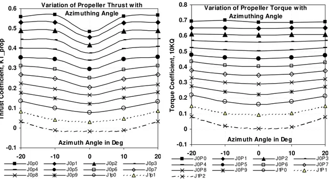
advance coefficients as indicated in the legends. The Figures show that propeller thrust and torque were minimum when it was operating at straight course condition, compared to ±10° and ±20° azimuth conditions (for the entire range of advance coefficient). Table 4 shows the performance variations of the propeller operating in straight course conditions compared to the azimuth conditions. In the calculation of differences in thrust and toque coefficients, equation 1 was used. In the calculation of differences in propulsive efficiency, equation 2 was used.
(
)
8 . 0/
100
_
%
= − −×
−
=
J ahead striaght azimuth ahead straightEta
Eta
Eta
Eta
Diff
…(2) As shown in table 4, and Figures 7(a) and 7(b), for all advance coefficients tested, the thrust and torque coefficients and propulsive efficiency for the propeller “only” were the lowest at straight course operating conditions (as indicated by negative sign of % Diffvalues in table 4). At the design advance coefficient of
J=0.8, an increase of 11.0% of KTprop was seen for the
propulsors with an azimuth angle of 20° port side, as compared to that of the propulsor in straight course. In the same operating conditions, an increase of 7.0%, 6.0% and 12.0% was seen for the propulsors in 10°, -10° and –20° azimuth angles. Thus, the percentage increases of thrust because of azimuth on either direction (Port or Star side) from the straight course condition are almost the same. Similar results were observed for all other advance coefficients. The percentage change of torque coefficients and propulsive efficiency of the propeller also behaved like that of the thrust coefficients. At advance coefficient of 0.8, an increase of 19.0%, 17.0%, 16.0% and 20.0% was seen for the propulsors in 20°, 10°, -10° and –20° azimuth angles. The results also showed that, as the azimuth angles changed from 0° to +20° or from 0° to -20°, the increases of thrust, torque and efficiency were nonlinear with the change of azimuth angles.
Propulsive Performance In Static Azimuthing Conditions Pod 2 in Puller Configuration
0.00 0.10 0.20 0.30 0.40 0.50 0.60 0.70 0.80 0.90 1.00 1.10 0.00 0.10 0.20 0.30 0.40 0.50 0.60 0.70 0.80 0.90 1.00 1.10 1.20 Advance Coefficient., J K T _p ro p 10 K Q an d E ffi ci e n cy Eta_Pod_Striaght Eta_Pod_10Star Eta_Pod_10Port Eta_Pod_20Star Eta_Pod_20Port KT_Pod_10Star KT_Pod_10Port KT_Pod_20Star KT_Pod_20Port KT_Pod_Straight 10KQ_10Star 10KQ_10Port 10KQ_20Star 10KQ_20Port 10KQ_Straight
Variation of Propeller Thrust w ith Azim uthing Angle
-0.1 0 0.1 0.2 0.3 0.4 0.5 0.6 -20 -10 0 10 20
Azim uth Angle in Deg
Thr u s t C o e ffi c ie n t, K T _ p ro p J0p0 J0p1 J0p2 J0p3 J0p4 J0p5 J0p6 J0p7 J0p8 J0p9 J1p0 J1p1 J1p2
Variation of Propeller Torque w ith Azim uthing Angle
-0.1 0 0.1 0.2 0.3 0.4 0.5 0.6 0.7 0.8 -20 -10 0 10 20
Azim uth Angle in Deg
T o rq u e C o ef fi ci en t, 10K Q J0P 0 J0P 1 J0P 2 J0P 3 J0P 4 J0P 5 J0P 6 J0P 7 J0P 8 J0P 9 J1P 0 J1P 1 J1P 2
Fig. 7(a)- Variation of thrust coefficients with azimuth angles at fixed advance coefficients.
Fig. 7(b)- Variation of torque coefficients with azimuth angles at fixed advance coefficients.
Table 4. Percent Difference in 20° Pull Podded Propeller and 15° Pull Podded Propeller Results
% Diff in KTprop % Diff in 10KQ % Diff in ηprop
KTprop 10KQ ηprop J 20° Port 10° Port -10° Star -20° Star 20° Port 10° Port -10° Star -20° Star 20° Port 10° Port -10° Star -20° Star 0.0 - 17.1 - 16.0 - 18.0 - 15.2 - 0.6 0.1 - 1.8 - 0.8 0.0 0.0 0.0 0.0 0.2 - 14.4 - 13.9 -14.5 - 14.9 -0.5 - 0.4 -0.3 -0.9 - 4.9 - 4.7 - 5.0 - 4.9 0.4 - 14.2 - 11.6 -11.3 - 12.2 -2.9 - 1.1 -0.8 -2.8 - 9.3 - 8.8 - 8.8 - 7.7 0.6 - 12.4 - 8.7 - 8.9 - 12.6 - 3.3 - 0.5 - 0.9 - 4.4 - 14.3 - 13.0 - 12.7 - 12.8 0.8 - 10.9 - 7.2 - 6.5 - 12.3 - 4.8 - 1.5 - 1.3 - 5.8 - 18.8 - 16.9 - 15.4 - 19.9 1.0 - 11.6 - 4.7 - 4.7 - 12.0 - 7.4 - 2.2 - 2.1 - 8.8 - 32.7 - 19.9 - 19.8 - 29.0
3-3. Influence of Azimuth Conditions on Unit Forces The forces and moment coefficients of Pod 2 for the range of advance coefficients and azimuth angle tested are presented in figures 8 to12. The longitudinal force
coefficients, KTX (also called unit thrust, KTunit)
decreased as the advance coefficients increased (see Figure 8). As the azimuth angles were increased from
0° to 20° or from 0° to –20°, the KTX decreased. An
exception occurred when the azimuth angles were changed from 0° to 10° (Port side) where a small
increase of KTX was seen. The reduction of the
longitudinal force was stronger for the negative azimuth direction, i.e. for right hand propeller, the clockwise
azimuth direction (in the present case, the –10° and – 20° azimuth conditions, see Figure 13b).
Figures 9 and 13(c) show the change of transverse force coefficients with advance coefficient and azimuth angles (at different fixed Js). The propulsors with positive azimuth angles showed an increasing transverse force with the increase of J, and the propulsors with negative azimuth angles showed a decreasing transverse force with the increase of J. The zero transverse force was found in the range of azimuth angles from –1° to -3.5° (clockwise azimuth) for all of the advance coefficients. The vertical force coefficient,
KFZ, also showed a similar trend as that of the KFY (see
with increase of azimuth angles and the zero vertical force occurred in the range of azimuth angles from 0° to 14° (counter-clockwise azimuth) for the range of advance coefficients tested. The moments around x-
and y-axis (KMX and KMY) are dependent on the
longitudinal and transverse forces, and the propeller torque. These moments also showed an increasing trend with increase of azimuth angles (see Figures 11 and
13(e)). The steering moment (vertical moment about z-axis) became zero in the range of azimuth angles from 4° to 10° (counter-clockwise azimuth) for the range of advance coefficients tested. As the azimuth angle increased, the steering moment increased in a non-linear fashion for the range of –20° to 20° azimuth angles (see Figures 12 and 13f).
Longitudinal Force Coefficients, KFX
-0.25 -0.15 -0.05 0.05 0.15 0.25 0.35 0.45 0.55 0.00 0.10 0.20 0.30 0.40 0.50 0.60 0.70 0.80 0.90 1.00 1.10 1.20 Advance Coefficient, J KF X KFx_10Star KFX_10Port KFX_20Star KFX_20Port KFX_Striaght
Fig. 8- longitudinal force coefficient plots for the Pod 2 at different azimuth conditions.
Transverse Force Coefficients, KFY
-0.35 -0.25 -0.15 -0.05 0.05 0.15 0.25 0.35 0.00 0.10 0.20 0.30 0.40 0.50 0.60 0.70 0.80 0.90 1.00 1.10 1.20 Advance Coefficient, J KF Y KFY_10Star KFY_10Port KFY_20Star KFY_20Port KFY_Straight
Vertical Force Coefficients, KFZ -0.30 -0.20 -0.10 0.00 0.10 0.20 0.30 0.00 0.10 0.20 0.30 0.40 0.50 0.60 0.70 0.80 0.90 1.00 1.10 1.20 Advance Coefficient, J KF Z KFZ_10Star KFZ_10Port KFZ_20Star KFZ_20Port KFZ_Straight
Fig. 10- Vertical force coefficient plots for the Pod 2 at different azimuth conditions.
Longitudinal Moment Coefficients, KMX
-0.85 -0.65 -0.45 -0.25 -0.05 0.15 0.35 0.55 0.75 0.00 0.10 0.20 0.30 0.40 0.50 0.60 0.70 0.80 0.90 1.00 1.10 1.20 Advance Coefficient, J KM X KMX_10Star KMX_10Port KMX_20Star KMX_20Port KMX_Straight
Fig. 11- longitudinal moment coefficient plots for the Pod 2 at different azimuth conditions.
Vertical (Steering) Moment Coefficients, KMZ
-0.10 -0.05 0.00 0.05 0.10 0.15 0.00 0.10 0.20 0.30 0.40 0.50 0.60 0.70 0.80 0.90 1.00 1.10 1.20 Advance Coefficient, J KM Z KMZ_10Port KMZ_10Star KMZ_20Star KMZ_20Port KMZ_Straight
(a) Test set-up and measurement location
Variation of Unit Thrust w ith Azim uthing Angle
-0.3 -0.2 -0.1 0 0.1 0.2 0.3 0.4 0.5 -20 -15 -10 -5 0 5 10 15 20 Azim uth Angle in Deg
T h ru st C o ef fi ci en t, K T _U n it J0p0 J0p1 J0p2 J0p3 J0p4 J0p5 J0p6 J0p7 J0p8 J0p9 J1p0 J1p1 J1p2
(b) Longitudinal force coefficient Variation of Transvers Unit force w ith
Azim uthing Angle
-0.35 -0.3 -0.25 -0.2 -0.15 -0.1 -0.05 0 0.05 0.1 0.15 0.2 0.25 0.3 -20 -15 -10 -5 0 5 10 15 20
Azim uth Angle in Deg
T ran sver se F o rce C o ef fi c ien t, K F Y J0p0 J0p1 J0p2 J0p3 J0p4 J0p5 J0p6 J0p7 J0p8 J0p9 J1p0 J1p1 J1p2
(c) Transverse force coefficient
Variation of Vertical Unit force w ith Azim uthing Angle
-0.25 -0.2 -0.15 -0.1 -0.05 0 0.05 0.1 0.15 0.2 0.25 -20 -15 -10 -5 0 5 10 15 20
Azim uth Angle in Deg
V er ti ca l F o rc e C o ef fi ci en t, K F Z J0p0J0p2 J0p1J0p3 J0p4 J0p5 J0p6 J0p7 J0p8 J0p9 J1p0 J1p1 J1p2
(d) Vertical force coefficient Variation of Axial Mom ent Coefficients w ith
Azim uthing Angle
-1 -0.8 -0.6 -0.4 -0.2 0 0.2 0.4 0.6 0.8 -20 -15 -10 -5 0 5 10 15 20
Azim uth Angle in Deg
A x ial M o m e n t C o e ff icie n t, K M X J0p0 J0p1 J0p2 J0p3 J0p4 J0p5 J0p6 J0p7 J0p8 J0p9 J1p0 J1p1 J1p2
(e) Longitudinal moment coefficient
Variation of Vertical (Steering) Mom ent Coefficients w ith Azim uthing Angle
-0.15 -0.1 -0.05 0 0.05 0.1 0.15 -20 -15 -10 -5 0 5 10 15 20
Azim uth Angle in Deg
V e rt ical Mo m e n t C o ef fi c ien t, K M Z J0p0 J0p1 J0p2 J0p3 J0p4 J0p5 J0p6 J0p7 J0p8 J0p9 J1p0 J1p1 J1p2
4 CONCLUDING REMARKS
The present set of experiments investigated the effects of propeller hub taper angle and azimuth angle on the propulsive performance of podded propulsors in puller configuration. Two pods were tested using the pod testing system at the OERC towing tank at Memorial University. The results have provided valuable insight into the effects of hub taper angle and azimuth angle on the propulsive performance of podded propulsor. The first set of experiments on the study of hub taper angle showed that, increasing the hub taper angle had an increasing effect on propeller efficiency in the range of advance coefficients tested. The propeller torque coefficient decreased approximately 2.0% as the hub angle was increased in the range of advance coefficients of 0.6 to 1.0. This resulted in a noticeable increase in propeller efficiency with increase in hub angle (4.0% increase in propeller efficiency at advance coefficient of 0.8). The podded unit with higher hub taper angle always produced higher unit thrust and the maximum increase was seen at moderate advance coefficients of 0.5 to 0.8 (approximately 5.0% increase at advance coefficient of 0.8). Similarly to the propeller efficiency and unit thrust coefficient, the pod unit with higher hub angle provided higher unit efficiency and maximum increase was seen at around design advance coefficient 0.8 (approximately 13.0% increase).
The influence of azimuth angle on the characteristics of puller-podded propulsors was dependent on the magnitude and direction of the azimuth angle. However, the thrust and torque of only the propeller were more or less independent of the azimuth direction. The thrust and torque coefficients for the propeller were lowest at straight course conditions. At the design advance coefficient of 0.8, an increase of 11.0% of propeller thrust coefficient was seen for the propulsors with an azimuth angle of 20°, as compared to that of the propulsor in straight course. In the same operating conditions, an increase of 7.0%, 6.0% and 12.0% was seen for the propulsors in 10°, -10° and –20° azimuth conditions. Similar results were observed for all other advance coefficients. The percentage change of torque coefficients and propulsive efficiency also behaved like that of the thrust coefficients. At advance coefficient of 0.8, an increase of 19.0%, 17.0%, 16.0% and 20.0% was seen for the propulsors in 20°, 10°, -10° and –20° azimuth angles. The results also showed that, as the azimuth angles changed from 0° to +20° or from 0° to -20°, the increases of thrust, torque and efficiency were nonlinear with the change of azimuth angles. It should be noted that, the increase of thrust, torque and efficiency of the propeller not necessarily means an increase in the whole unit thrust and efficiency, where the drag of the pod-strut is also included.
The force and moment coefficients of the propulsors showed a strong dependence on the propeller advance coefficient and azimuth angle. The longitudinal force coefficient was decreasing with the increasing advance coefficients and for both azimuth directions (±20°). The reduction of the longitudinal force was stronger for the negative azimuth direction, i.e. for right hand propeller, the clockwise azimuth direction (in the present case, the –10° and –20° azimuth conditions). The propulsors with positive azimuth angles shows as increasing transverse force with the increase of J and vice versa. The zero transverse force was found in the range of azimuth angles from –1° to -3.5° (clockwise azimuth) for all of the advance coefficients. The vertical force coefficient also showed a similar trend as that of the transverse force coefficient. It showed an increasing trend with increase of azimuth angles and the zero vertical force occurred in the range of azimuth angles from 0° to 14° (counter-clockwise azimuth) for the range of advance coefficients tested. The moments around x- and y-axis also showed an increasing trend with increase of azimuth angles. The steering moment (vertical moment about z-axis) became zero in the range of azimuth angles from 4° to 10° (counter-clockwise azimuth) for the range of advance coefficients tested. As the azimuth angle increased, the steering moment increased in a non-linear fashion for the range of –20° to 20° azimuth angles.
ACKNOWLEDGEMENTS
The authors thank the Natural Sciences and Engineering Research Council (NSERC) Canada, Oceanic Consulting Corp., Thordon Bearings Inc., the National Research Council (NRC), and Memorial University for their financial and other support. Thanks are also extended to Andrew MacNeill of Oceanic Consulting, Jim Gosse and the technical service stuff of Memorial University.
REFERENCES
CARLTON, J.S., (2002), “Podded Propulsors: some design and service experience”, The Motor Ship Marine Propulsion Conference, Copenhagen, Denmark, April 9-10, 7p.
GALWAY R. D., (1980), “A Comparison of Methods for Calibration and Use of Multi-Component Strain Gauge Wind Tunnel Balances”, Aeronautical Report LR-600, NRC No. 18227, National Aeronautical Establishment, National Research Council, Canada, 40p.
HE, M., VEITCH B., BOSE N., BRUCE C. AND LIU P., (2005), “Numerical Simulations of Propeller Wake
Impacting on a Strut”, Proceedings of the CFD2005, St John’s, NL Canada, August, 8p.
HE, M., VEITCH B., BOSE N. AND LIU P., (2005), “An Investigation on Wake/Strut Interaction of a
Tractor-Type Podded Propulsor”, Proceedings of the 7th
CMHSC, Halifax, NS Canada, September 21-22, 8p. HEINKE, H.J., (2004), “Investigation about the Forces and Moments at Podded Drives”, In Proc. of the 1st International Conference on Technological Advances in Podded Propulsion, Newcastle University, UK, April, pp. 305-320.
HESS D.E., NIGON R.T., BEDEL J.W., (2000), “Dynamometer Calibration and Usage”, Research and Development Report No. NSWCCD-50-TR-2000/040, Hydromechanics Directorate, Carderrock Division, Naval Surface Warfare Center, West Bethesda, Maryland, 31p.
ISLAM, M. F., (2004), “Numerical investigation on effects of hub taper angle and Pod-strut geometry on propulsive performance of pusher Propeller configurations”, Master’s of Engineering thesis, Memorial University of Newfoundland, Canada, 136 p. ISLAM, M. F., TAYLOR, R., QUINTON J., VEITCH, B., BOSE, N., COLBOURNE, B. AND LIU, P., (2004), “Numerical investigation of propulsive characteristics of podded propeller”, Proceedings of the 1st International Conference on Technological Advances in Podded Propulsion, Newcastle University, UK, April, pp. 513-525.
ISLAM, M. VEITCH, B., BOSE, N. AND LIU, P., (2005), “Cavitation Characteristics of Pushing and Pulling Podded Propellers With Different Hub Taper
Angles”, Proceedings. of the 7th CMHSC, Halifax, NS
Canada, September 21-22, 7p.
ISLAM, M. VEITCH, B., BOSE, N. AND LIU, P., (2006), “Numerical Study of Hub Taper Angle on Podded Propeller Performance”, Journal of Marine Technology, Vo. 43, No.1, pp.1-10.
ITTC – Recommended Procedures, (2002), “Propulsion, Performance - Podded Propeller Tests and Extrapolation”, 7.5-02-03-01.3, Revision 00.
PAKASTE, R., LAUKIA, K., WILHELMSON, M., KUUSKOSKI, (1999), “Experience with Azipod® propulsion systems on board marine vessels", ABB
Review, Issue 2, 12p.
MOLLOY, S., ISLAM, M. F., HE. M., VEITCH, B., BOSE, N., WANG, J., AKINTURK, A. AND LIU, P., (2005), “Use of factorial design in podded propulsors
geometric series”, Proceedings of the 7th CMHSC,
Halifax, NS Canada, September 21-22, 8 p.
MACNEILL, A., TAYLOR, R., MOLLOY, S., BOSE, N., VEITCH, B., RANDELL, T. AND LIU, P., (2004), “Design of model pod test unit”, Proceedings of the 1st International Conference on Technological Advances in Podded Propulsion, Newcastle University, UK, April, pp. 447-458.
MEWIS, F., (2001), “The efficiency of pod propulsion”, HADMAR 2001, Bulgaria, October, 7p. SZANTYR, J.A., (2001), “Hydrodynamic Model Experiments with Pod Propulsor”, International Symposium of Ship Propulsion (Lavrentiev Lectures), State Marine Technical University, St. Petersburg, Russia, pp. 95-104.
SZANTYR, J.A., (2001), “Hydrodynamic Model Experiments with Pod Propulsor”, Oceanic
Engineering International, Vol. 5, No.2, pp. 95-103. GRYGOROWICZ, M. AND SZANTYR, J.A., (2004), “Open Water Experiments with Two Pods Propulsor Models”, In Proc. of the 1st International Conference on Technological Advances in Podded Propulsion, Newcastle University, UK, April, pp. 357-370.
STETTLER, J.W. AND HOVER, F.S., TRIANTAFYLLOU, M.S., (2004), “Preliminary Results of Testing on the Dynamics of an Azimuth Podded Propulsor Relating to Vehicle Manoeuvring”, In Proc. of the 1st International Conference on Technological Advances in Podded Propulsion, University of Newcastle, UK, pp. 321-338.
TAYLOR, R. VEITCH, B., BOSE, N., (2005), “The Influence of Hub Taper Angle on Podded Propeller Performance: ‘Propeller Only’ Tests vs. ‘Podded
Propeller Unit’ Tests”, Proceedings of the 7th CMHSC,
Halifax, NS Canada, September 21-22, 8p.
TAYLOR R, (2005), “Experimental Investigation of the Influence of Hub Taper Angle on the Performance of Push and Pull Configuration Podded Propellers”, Master’s of Engineering Thesis, Memorial University of Newfoundland, Canada, 120p.