HAL Id: hal-03091168
https://hal.archives-ouvertes.fr/hal-03091168
Submitted on 30 Dec 2020HAL is a multi-disciplinary open access archive for the deposit and dissemination of sci-entific research documents, whether they are pub-lished or not. The documents may come from
L’archive ouverte pluridisciplinaire HAL, est destinée au dépôt et à la diffusion de documents scientifiques de niveau recherche, publiés ou non, émanant des établissements d’enseignement et de
Synthesis and (some) applications of
carbon-nanotube-supported pyrolytic carbon nanocones
Germercy Paredes, Grégory Seine, Robin Cours, Florent Houdellier, Hatem
Allouche, Thierry Ondarçuhu, Fabrice Piazza, Marc Monthioux
To cite this version:
Germercy Paredes, Grégory Seine, Robin Cours, Florent Houdellier, Hatem Allouche, et al.. Synthesis and (some) applications of carbon-nanotube-supported pyrolytic carbon nanocones. Indian Journal of Engineering and Materials Sciences, CSIR-NISCAIR, In press. �hal-03091168�
Synthesis and (some) applications of carbon-nanotube-supported pyrolytic
carbon nanocones
Germercy Paredes1,2, Grégory Seine1, Robin Cours1, Florent Houdellier1, Hatem Allouche1,
Thierry Ondarçuhu3, Fabrice Piazza2, Marc Monthioux1
1Centre d’Elaboration des Matériaux et d’Etudes Structurales (CEMES), UPR-8011 CNRS,
Université de Toulouse, France.
2Laboratorio Nanociencias, Pontificia Universidad Católica Madre y Maestra, Santiago de Los
Caballeros, Dominican Republic.
3 Institut de Mécanique des Fluides (IMFT) de Toulouse UMR 5502, Toulouse, France.
I. Introduction
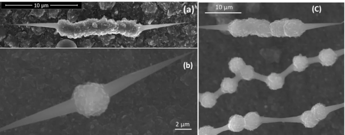
All-graphene carbon cones with nanosized apex can be obtained by means of high temperature pyrolytic carbon deposition process using methane and hydrogen as gaseous feedstock and individual carbon nanotubes (CNTs) as deposition substrates1,2. Aside the cones
with smooth surface, micrometer-sized carbon beads (Figures 1b and 1c) or fiber segments (Figures 1a and 1c) are deposited meanwhile, which are a key morphological component for allowing handling and mounting the carbon cones and then using them for various applications.
Figure 1. (a) Morphology of a "carbon nanocone" with a fiber segment. (b) Morphology of a
nanocone" morphology types: chains of carbon beads linked by truncated cones, and a fiber-segment/cone morphology.
Figure 2. Carbon nanocone texture and nanotexture. (a) High resolution transmission electron
microscopy (HRTEM) image showing a perfect orientation of the nanocone graphene layers with respect to the cone axis (primary carbon nanotube). As indicated (see arrows) the cone surface is made of graphene edges, each of them being a preferred site for adsorption. (b) Display of the constituting graphenes within the conical part (model by I. Suarez-Martinez, Curtin University, Australia).
II. Synthesis and growth mechanisms
CNTs are grown first, using iron nanoparticles as catalyst combined with a regular chemical vapor deposition process (CCVD) in which a CH4 + H2 feedstock is cracked at 1000-1100°C2.
Then catalyst-free conditions (CVD) involving temperatures in the 1300-1500°C range and a modified H2/CH4 ratio are used to deposit pyrolytic carbon onto each CNT, which
spontaneously adopt the complex morphologies as shown in Figure 1 while aligning more or less periodically along the CNTs1-4. A deposition mechanism which requires both the presence
of small carbon radicals and the transient formation of pitch-like (i.e., containing polyaromatic hydrocarbon molecules (PAHs) and lighter hydrocarbons) droplets in the gas phase is proposed, based on both the literature and experimental evidences4 (Figure 3).
Figure 3. sketch of the formation mechanisms of the carbon nanocone-bearing morphologies
seen in Figure 1. A: growth of the primary CNTs; B: deposition of pitch-like (PAH-containing) droplets onto the CNTs, forming double meniscus; C: PAHs align parallel to the CNT axis upon surface tension forces and then subsequently carbonise, forming bicones; D: Growth of the cones mostly from C radicals, while the short fiber segments (or beads) form mostly from droplets.
At the beginning of the deposition process, radicals cannot chemisorb onto the CNTs because of the lack of active sites. Therefore, based on ref.4, the proposed mechanism for the early
deposition step is related to the wettability of the substrate (the primary nanotube surface) by the carbon species (PAH-containing droplets) where the deposition and carbonization processes take place. Because of the substrate geometry (non-planar), two situations of partial wetting define the way droplets are deposited onto the nanofilament. These situations depend on the nanotube over droplet diameter ratio. Should the droplets exhibit diameters smaller than the CNT diameters (5-10 nm), they would deposit on the filament surface as they would onto a planar surface, corresponding to the first situation. The second situation occurs when the carbon nanotubes have smaller diameters than droplets. In such a case, each PAH-rich droplet is deposited onto the carbon nanotube surface forming a double meniscus (Figure 3b). The primary droplet deposition event is assumed to be somewhat periodic following the Plateau-Rayleigh instability5. These double menisci are responsible for forming the primary
double nanocones observed in short duration experiments (step C in Figure 3)4. Indeed, The
PAHs from the liquid double meniscus align parallel to the nanotube because of capillary forces and surface tension and then carbonize as concentric graphenes (step C in Figure 3). The cones continue growing the same way until a threshold value of about 100 nm for the
diameter at the cone base is reached. At the reached threshold value, the deposition of the droplets continues at the base of the double cones now following situation 1 above-mentioned, because at that time, the radius of curvature of the substrate surface has become long enough for the droplets to deposit on it as they would do onto a flat substrate. From this moment, the graphenes resulting from the carbonization of the PAHs no longer align well, because the effect of surface tensions no longer prevails, producing morphologies with rough surface. Rough surface sub-morphologies can be bead-like or fiber-segment-like (Figure 1) probably depending on the number of droplets in the gas phase. Once this step is reached, the cones and the beads/fiber segments continue to grow simultaneously, but now driven by a competition between the two carbon deposition modes: the chemisorption of radicals onto the active sites present at the cone surface and the physisorption of PAH-rich droplets mostly onto the bead/fiber-segments, respectively.
III. Application of carbon cones as electron emitters
The concentric texture and the graphene perfection of the carbon cones are likely to provide them with the physical properties of large multiwall CNTs, typically, high electrical and thermal conductivities, high current density, and high flexural resilience, yet with an apex in the ~5-10 nm range only. Therefore, carbon cones were successfully tested as electron emitters instead of the usual W emitter, in cold-field emission guns (CFEG) (Figure 4a), the best current electron sources for electron microscopes. Results overpassed the expectations, and the carbon cone emitter revealed to be able to provide 5 times higher reduced brightness and better coherence than any commercial electron source for TEM6-8. They also are better than
pristine CNTs, because of the conical shape which provides sufficient mechanical stability to prevent the tip from vibrating while emitting.
Overall, the carbon cone electron source exhibits much better time stability than the best CFEG on market (Figure 4b), presumably because much fewer active sites are present at the cone surface (Figure 2a) with respect to the tungsten crystal, leaving the residual species present in the ultravacuum atmosphere with little opportunity to adsorb and thereby
Figure 4. (a) Carbon cone W-welded by focused ion beam onto a regular yet truncated W tip
emitter. (b) comparison of the current stability with time for 1) the carbon cone emitter; (b-2) a regular W tip emitter. Such a stability is unprecedented for CFEG electron source (from ref.8).
preventing the current from dropping. Indeed, as the cones are made of concentrically displayed perfect graphenes, the only active sites at the cone surface are the graphene edges, which occurrence is in the range of one every 7-10 nm on the cone side (Figure 2a) and 2-3 nm in the vicinity of the cone apex (Figure 5b). On the opposite, for a chemically-etched single-crystal tungsten-tip, every surface atom is under-coordinated, hence is reactive towards the residual species, which makes one active site every 2-3 Angströms at the tip surface. Carbon cones were then patented for this application9.
IV. Application of carbon cones as probes for scanning probe microscopy
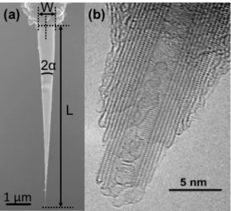
The aspect ratio and electrical conductivity property (which is expected from the perfect nanotextural quality, see Figure 2) make the carbon cones presumably suitable as probes for various modes of near field microscopy. The carbon nanocone shape have a length L in the range of (2-7 µm) and a base-width W of about up 700 nm, and a very sharp apex angle noted
2α. The smallest the cone radius W/2, the closest to zero the cone angle. This very small angle
can be estimated by the following equation:
Tan α = α = W/(2 * L) (1)
this leads to:
2α = W/L (2)
For W = 700 nm; L = 6 µm (maximum value) as depicted in Figure 5a, the cone angle 2α takes the value of 0.12°.
Figure 5. Main geometrical characteristics of a nanocone tip. (a) SEM image showing the
length, width and angle parameters. (b) High resolution transmission electron microscopy (HRTEM) image of the cone apex. (Photo credit: R. Wang, CEMES-CNRS).
Carbon cone morphologies such as shown in Figure 1a were glued onto tailor-made AFM cantilevers (obtained from AppNano) following either a micro-manipulation procedure under optical microscope as initially proposed by Dai et al. for CNTs10, or the same focused electron
beam-induced welding techniques as carried-out for mounting the cones as electron emitters6,7. In the latter case, the mounting process was conducted using a Scanning Electron
Microscope (SEM Zeiss 1540 XB) equipped with a dual Focused Ion Beam (FIB) Electron Beam system and a micromanipulator (clamps) as depicted in Figure 6. Subsequently, tests of the probes for different conductive and non-conductive SPM modes were conducted.
Figure 6. Mounting a carbon nanocone tip as SPM probe by focused electron-beam-induced
metal deposition. (a) A carbon nanocone morphology is grabbed by micromanipulator clamps; (b) The carbon nanocone morphology is placed into the groove of a specially-designed Si-doped cantilever; (c) The carbon nanocone tip (welded onto the cantilever) is ready to be used for different AFM tests: the yellow colour represents a Si doped cantilever, the purple colour, the carbon cone tip morphology, and the red parts correspond to the platinum metal deposit used for welding.
Carbon nanocones exhibit better resolution than standard AFM Si tips when used for AFM-tapping mode topography images (Figure 7). The images parameters of a scan size area of 500 nm width with a speed scan of 2hz and 256 X 256 scan pixels allowed distinguishing the background of a silicon wafer surface as well as the separation between two gold nanoparticles which are clearly delimited thanks to the tip sharpness of the carbon cone tip (Figure 7b). Thanks to their carbon nature, these conical tips are also suitable for near-field modes requiring conducting probes, such as conducting AFM, charge injection, and Kelvin force microscopy, for which they have already shown a promising behaviour11. Other
conductive modes such as C-AFM, Scanning Tunnel Microscopy (STM), and non-conductive ones such as Peak-Force Quantitative Nanomechanical Mapping (PFQN AFM)- are currently tested, and work in this area is in progress.
Figure 7. (a) AFM image obtained from a commercial Si probe on gold nanoparticles deposited
on a Si wafer; (b) Same area as (a) using a carbon cone probe.
V. Conclusions
In summary, we have shown that unique carbon conical morphologies can be produced from pyrolytic carbon deposition onto nanoscale substrates (carbon nanotubes) during a thermal CVD process. The fact of synthetizing micro-nano morphologies made up of smooth nanocones as well as rough bead or fiber segments, suggest (at least under experimental conditions of high temperature and atmospheric pressure) a pyrolytic carbon deposition driven by two different mechanisms. This can be explained by the coexistence (in the gas phase) of carbon radicals, which provide the needed active sites, in addition to PAH-containing droplets which randomly deposit wherever onto the substrate surface.
On the other hand, it was demonstrated that the well-controlled geometrical characteristics (i.e. aspect ratio, tip radius) of the synthesized morphologies, and their excellent physical properties (i.e. good electrical conductivity, mechanical strength) as well as their relatively easy mounting, allow them to have the potential to equip electron sources with unprecedented performances, and to be unique, presumably durable, multi-mode probes for various kinds of near-field microscopy.
Acknowledgments
The Pontificia Universidad Católica Madre y Maestra (Santiago, Dominican Republic) is thanked for providing the grant for GP. The LabEx NEXT is thanked for funding the "CarboProbe" project and mutual visits.
References
1. Jacobsen R L & Monthioux M, Nature 385 (1997) 211-212.
2. Allouche H, Monthioux M & Jacobsen R L, Carbon 41 (2003) 2897-2912. 3. Allouche H & Monthioux M, Carbon 43 (2005) 1265-1278.
4. Monthioux M, Allouche H & Jacobsen R L, Carbon 44 (2006) 3183-3194.
5. Haefner S, Benzaquen M, Bäumchen O, Salez T, Peters R, McGraw J D, Jacobs K, Raphaël E & Dalnoki-Veress K, Nature Communications 6 (2015) 7409.
6. Houdellier F, Masseboeuf A, Monthioux M & Hÿtch M J, Carbon 50 (2012) 2037-2044. 7. Houdellier F, de Knoop L, Gatel C, Masseboeuf A, Mamishin S, Taniguchi Y, Delmas M,
Monthioux M, Hÿtch M J & Snoeck E, Ultramicroscopy 151 (2015) 107-115.
8. Mamishin S, Kubo Y, Cours R, Monthioux M & Houdellier F, Ultramicroscopy 182 (2107) 303-307.
9. Monthioux M & Houdellier F, European Patent (pub. EP 2-617-049-B1), delivered October 10 (extended to Japan, USA), 2018.
10. Dai H, Hafner J H, Rinzler A G, Colbert D T & Smalley R E, Nature 384 (1996) 147-150. 11. Paredes G, Seine G, Palleau E, Delmas M, Ressier L, Cours R, Masseboeuf A, Ondarçuhu
T, Piazza F & Monthioux M, Proc. of The World Conference on Carbon 'Carbon-2018', Madrid (Spain), Ext. Abstr. #837.
Abstract
Graphene-based cones with nanosized apex can be obtained by means of high temperature pyrolytic carbon deposition process using methane and hydrogen as gaseous feedstock and single carbon nanotubes as deposition substrates. Aside the cones, micrometer-sized carbon beads or fibre segments are deposited meanwhile which are a key morphological component for allowing handling and mounting the carbon cones and then using them for various applications. Based on both the literature dealing with pyrolytic carbon deposition processes and experimental observations, a peculiar deposition mechanism is proposed, involving the transient formation of pitch-like liquid phase droplets which deposit onto the individual carbon nanotubes. In this picture, it is believed that a key parameter is the ratio between the droplet and the nanotube diameters, respectively. The cone concentric texture and perfect nanotexture are shown by high resolution transmission electron microscopy, which allows interesting mechanical and conducting properties to be predicted. Correspondingly, applications of the carbon nanocones as electron emitters for cold-field electron sources on the one hand, and as probes for various modes of near-field microscopy on the other hand, have been tested.
Figure captions
Figure 1. (a) Morphology of a "carbon nanocone" with a fiber segment. (b) Morphology of a
"carbon nanocone" with an isolated carbon bead. C) Co-existence of different "carbon nanocone" morphology types: chains of carbon beads linked by truncated cones, and a fiber-segment/cone morphology.
Figure 2. Carbon nanocone texture and nanotexture. (a) High resolution transmission electron
microscopy (HRTEM) image showing a perfect orientation of the nanocone graphene layers with respect to the cone axis (primary carbon nanotube). As indicated (see arrows) the cone surface is made of graphene edges, each of them being a preferred site for adsorption. (b) Display of the constituting graphenes within the conical part (model by I. Suarez-Martinez, Curtin University, Australia).
Figure 3. sketch of the formation mechanisms of the carbon nanocone-bearing morphologies
seen in Figure 1. A: growth of the primary CNTs; B: deposition of pitch-like (PAH-containing) droplets onto the CNTs, forming double meniscus; C: PAHs align parallel to the CNT axis upon surface tension forces and then subsequently carbonise, forming bicones; D: Growth of the cones mostly from C radicals, while the short fiber segments (or beads) form mostly from droplets.
Figure 4. (a) Carbon cone W-welded by focused ion beam onto a regular yet truncated W tip
emitter. (b) comparison of the current stability with time for 1) the carbon cone emitter; (b-2) a regular W tip emitter. Such a stability is unprecedented for CFEG electron source (from ref.8).
Figure 5. Main geometrical characteristics of a nanocone tip. (a) SEM image showing the
length, width and angle parameters. (b) High resolution transmission electron microscopy (HRTEM) image of the cone apex. (Photo credit: R. Wang, CEMES-CNRS).
Figure 6. Mounting a carbon nanocone tip as SPM probe by focused electron-beam-induced
metal deposition. (a) A carbon nanocone morphology is grabbed by micromanipulator clamps; (b) The carbon nanocone morphology is placed into the groove of a specially-designed Si-doped cantilever; (c) The carbon nanocone tip (welded onto the cantilever) is ready to be used for different AFM tests: the yellow colour represents a Si doped cantilever, the purple colour, the carbon cone tip morphology, and the red parts correspond to the platinum metal deposit used for welding.
Figure 7. (a) AFM image obtained from a commercial Si probe on gold nanoparticles deposited