HAL Id: hal-02474087
https://hal.archives-ouvertes.fr/hal-02474087
Submitted on 19 Feb 2020
HAL is a multi-disciplinary open access archive for the deposit and dissemination of sci-entific research documents, whether they are pub-lished or not. The documents may come from teaching and research institutions in France or abroad, or from public or private research centers.
L’archive ouverte pluridisciplinaire HAL, est destinée au dépôt et à la diffusion de documents scientifiques de niveau recherche, publiés ou non, émanant des établissements d’enseignement et de recherche français ou étrangers, des laboratoires publics ou privés.
Applications
van Hieu Nguyen, Aliou Diallo, Philippe Le Thuc, Robert Staraj, Stéphane
Lanteri, Georges F. Carles
To cite this version:
van Hieu Nguyen, Aliou Diallo, Philippe Le Thuc, Robert Staraj, Stéphane Lanteri, et al.. A Miniature Implanted Antenna for UHF RFID Applications. Progress In Electromagnetics Research C, EMW Publishing, 2020, 99, pp.221-238. �10.2528/PIERC19102905�. �hal-02474087�
Van Hieu NGUYEN* 1, Aliou DIALLO1, Philippe LE THUC1, Robert STARAJ1, Stephane LANTERI2 and Georges F. CARLE3
Abstract—In this paper, the design of a miniature antenna dedicated to be implanted in a small animal and intended to work in the European UHF RFID (865-868 MHz) band is presented. One of the goals of this work is the miniaturization of the radiating element while preserving its efficiency to allow a reliable communication between an external interrogating reader and the implanted device. The radiating element is a small rectangular loop antenna associated to a dipole allowing the impedance matching. The antenna has dimensions of 2.4 mm x 25.4 mm x 0.5 mm and integrates an Impinj Monza 4 chip presenting an impedance of 5.5-j74 Ohms at 868 MHz. The antenna is designed and optimized by using the ANSYS HFSS software. The obtained results show a simulated radiation efficiency of 0.7% and a simulated total gain of -17.5 dBi. A prototype was realized and RSSI measurements have demonstrated the possibility of reliable wireless communications between the implanted antenna and an external reader. In addition, Specific Absorption Rate (SAR) calculation indicates that this implanted antenna meets the required safety regulations.
1. INTRODUCTION
The monitoring of small animals in laboratory tests and the remote analysis of their behavior in real time interest researchers for a long time. This monitoring can be done by using implanted miniature wireless sensors. Thus, electronic radio telemetry capsules were invented in the 1950’s and were used to measure temperature and pressure [1]. These capsules can integrated numerous electronic components such as battery, digital signal processor, light emitting diodes, camera, other sensory devices and at least one antenna which is one of the most difficult components to design for this kind of application [2]. Indeed, the main difficulty in designing antennas for bio-implantable communication devices is to provide an efficient radiating structure, despite the volume constraints and the high impact of the surrounding biological tissues which constitute a dispersive environment and reduce the antenna radiating performance such as its efficiency [3], [4].
Although many studies have focused on the design of implanted antennas dedicated to the MICS band (402-405 MHz) [5], [6], it should be noted that at these frequencies, the size of the antennas and the use of battery can be a real disadvantage in the case of small animals which require miniature structures [7].
Thus, the use of RFID (Radio Frequency IDentification) technology in the European UHF band (865-868 MHz) can be a good solution because it has two major advantages: it facilitates the implementation of the tag and does not require the addition of a battery to power the implanted device [8]. Recently, several research papers have presented implantable antenna solutions dedicated to the UHF bands (868 or 915 MHz) and using the RFID technology. For example, in [9] a folded dipole antenna for an implantable RFID tag working in the US UHF band has been proposed. This structure of dimensions 4 x 22 mm2 works as a loop antenna and is intended to be implanted in a human body. This type of antenna possesses a dominant magnetic field and may not be able to communicate effectively with interrogating antennas having a dominant electric field. Moreover, unfortunately, its performance in terms of efficiency and gain are not given by the authors. In [10], the design and characterization of a compact multilayer passive UHF-RFID tag solution for implantable biotelemetry based on Low-Temperature Co-fired Ceramic (LTCC) technology is presented. It consists in a spiral PIFA (Planar Inverted-F Antenna) antenna matched to an UHF embedded integrated circuit source thanks to an
inductor line. However, except the antenna bandwidth, neither its efficiency nor its gain are given. In [11], a cylindrical antenna presenting dimensions of 55.2 x π x 25 mm3 and destinated to be implanted
in human living tissues is proposed. Despite its good performance, its global dimensions do not allow its implantation in small animals such as mice. Thus, for the design and optimization of this type of antenna, the use of methods like the genetic algorithm can be very useful [12].
This work aims at the wireless identification and positioning of small animals in a standard housing environment. In order to make the communication possible, a trade-off needs to be found between two main parameters of the antenna: its efficiency and its volume. Indeed, on one hand, its radiation efficiency must be sufficient to maintain the communication between the implant also called tag (consisting of the antenna and the RFID chip) and the reader. On the other hand, the antenna volume must be sufficiently small to limit the disturbances that the device may create on the animal habits. Moreover, the antenna of the implanted tag must be biocompatible, meaning that it must be covered with a material tolerated by the organism to prevent the possibility of rejection by the animal body [6], [13] and [14].
In [15], a novel tag antenna intended for small animal identification application has been designed and the link budget calculation of this implanted antenna was presented. In this paper, the detail process allowing to achieve this antenna is presented more in detail. First, in section 2, the link budget is calculated to determine the minimum tag antenna performance suitable for a reliable communication within the framework of the desired application. Then, in section 3, the proposed initial antenna is optimized by using some techniques leading to the final design and its performance are compared with those of other existing solutions. In section 4, the electric and magnetic fields as well as the SAR (Specific Absorption Rate) distribution are also studied. Finally, a prototype has been realized and measured in environmental conditions close to the final application.
2. LINK BUDGET CALCULATION
The objective of this section is to calculate the necessary minimal gain of the implanted antenna allowing a reliable communication between an external reader and the implanted tag. The latter is placed at a depth of 2 mm in a homogeneous phantom model whose dielectric properties are equivalent to those of the different layers of tissues present in small animals, which are skin, muscle and bone. The values of the dielectric permittivity, loss tangent, conductivity and thickness of each layer are given in Table 1. The total equivalent dielectric permittivity εreq, loss tangent tanδeqand conductivity σeqare respectively
39.6, 0.39 and 0.79 (S/m) [16] - [20].
Table 1. Electric properties of the different tissues.
εr tanδ σ (S/m) T hickness (mm)
Skin 41.05 0.28 0.64 2.0 M uscle 56.90 0.45 1.27 5.5 Bone 23.00 0.34 0.39 6.0
The reader antenna is positioned in a confined space with reduced dimensions and has a limited gain of 3.2 dBi. The power emitted by the reader is limited to Ptx reader = 27 dBm (reader’s output power)
in order to respect the ERC (European Radiocommunications Committee) recommendations for the ISM band at 868 MHz which impose a maximum power of 500 mW (27 dBm) [21]. The characteristics of the reader and its antenna are given in Table 2.
There are two models for defining the near field and far field regions around an electromagnetic source based on the largest dimension D of antenna and the wavelength λ: the three-region model and the two-region model [22]. In our application, D is the diagonal length of the reader antenna ground plane and is equal to 141 mm. In this case, D/2 is greater than λ/2π, defined as the radius of the Wheeler sphere [23]. So, the tag antenna is located in the near field of the interrogating antenna and the formula to be used for the link budget calculation of the forward path is (1) [24].
Table 2. Reader Parameters.
Reader sensitivity Reader trans. power Ptx reader Reader antenna gain Greader
-82 dBm 27 dBm 3.2 dBi
Prx tag = Ptx readerGtagGreader(
λ 4πR) 2[1 − λ2 (2πR)2 + λ4 (2πR)4] (1)
For this near field calculation, the part of ∆ = [1 − (2πR)λ2 2 + λ 4
(2πR)4] represents an attenuation of
0.71 dB (with R=58 mm, the distance between two antennas) by compare to the Friis formula in the far field. For the reverse path, a similar analysis leads to the conclusion that the communication link is now made in the far field of the implanted antenna. That is why the Friis equation is used according to the specifications of the tag antenna design.
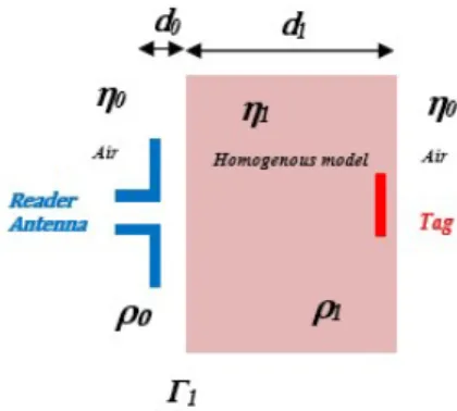
If we note di (i = 0, 1) the length of the propagation channel of the wave in each medium (Figure
1), d0 the thickness of the air layer and d1 the equivalent thickness of the animal body layers, the
attenuation of the medium Am is then defined by:
Am= (
4πdi
λi
)2e−αidi (2)
where α0 = 0 is the attenuation constant of the air and α1 is the equivalent attenuation in the
animal body: α1 = ω v u u t µreqεreq 2 [ s 1 + ( σeq ωεreq )2− 1] (3)
with µreqequals to 1 in our study. Moreover, we consider that the incident wave propagates through
the different media as shown in Figure 1, with different impedances producing a global loss represented by Lint at the interface between air and body. Lint is obtained by the equations given in [25] from the
value of the reflection coefficient Γ1 (6) which can be expressed directly in terms of d1 and ρi (5).
Figure 1. Transmission and reflection model on the dielectric layer.
ρ0 = η1− η0 η1+ η0 (4) ρ1 = η0− η1 η0+ η1 (5)
Γ1 =
ρ0+ ρ1e−j2k1d1
1 + ρ0ρ1e−j2k1d1
(6)
Lint= |Γ1|2 (7)
In Figure 1, ρ0 and ρ1 denote respectively the elementary reflection coefficients between the air
and the animal body and between the animal body and the air, k1 = 2π/λ1 is the wave number in the
body, and λ0 is the wavelength in the air. η0 and η1 are the impedances of the air layer and animal
body respectively, and are defined by:
η0 = rµ 0 ε0 (8) η1 = s µreqµ0 εreqε0 (9) Thus, based on the reader’s performance, a tag sensibility Prx tag min about -16.9 dBm [26], the
attenuation Am in the animal environment and the losses Lint at the interface between the air and
the animal environment, the minimum value of the implantable antenna gain Gtag min allowing the
communication forward link in this environment can be estimated as: Gtag min=
Prx tag minPLintPAm
Ptx readerGreader
(10) The backscattered power by the implanted tag received by the RFID reader must be greater than its sensitivity (the minimum power required to detect the feedback signal of the tag) to guarantee the communication. For the reverse communication link, the power received by the reader can be determined by the following relation [27], [28], where Lmodulation represents the modulation losses estimated at -3
dB [25].
Prx reader(dBm) = Ptx tag+ Greader+ Gtag+
X Lint+
X
Am+ Lmodulation (11)
Table 3. Calculated parameters.
Am Lint Gtag min Prx reader
25 dB 7.5 dB -28.9 dBi -55.2 dBm
Table 3 summarizes the obtained values for the different parameters for the whole forward-reverse link. Gtag minis obtained by using (10) and Prx reader, which is the received power of the reader antenna
(11). Thus, it will be necessary to have a minimum implanted antenna gain Gtag min of -28.9 dBi so
that the reader can detect the power returned by the tag.
3. DESIGN OF THE UHF RFID TAG IMPLANTED ANTENNA 3.1. Design and optimization of the antenna in its environment
The antenna optimization was done while the radiating element was placed in a homogenous phantom (Figure 2) having a cylindrical shape and a total volume of π x 13.52 x 70 mm3. The geometry of the antenna is shown in Figure 3. It is composed of a dipole printed on a Duroid substrate (permittivity εr
= 2.2, dielectric loss tangent tanδ = 0.0009 and thickness h=0.127mm) excited by coupling with a loop antenna, which is associated with an Impinj Monza 4 chip [26]. This chip presents an impedance ofR
5.5-j74 Ohms at 868 MHz and is enclosed in a Silicone insulating layer of thickness ts(εr = 3.3 and tanδ
and also to facilitate the transition of the radiating wave between the implanted antenna and the small animal tissues [8]. Moreover, as the thickness of the insulator layer has an influence on the resonance frequency of the antenna, its radiation efficiency and also on the SAR (Specific Absorption Rate), these parameters will be determined later.
Figure 2. Implanted tag in the homogeneous body phantom.
Figure 3. Geometry of the antenna: (a) top view, (b) bottom view and (c) side view.
To match the antenna to the complex impedance of the chip, it is necessary to obtain an antenna input impedance equals to the complex conjugate of the chip one i.e. 5.5 + j74 Ohms [26]. The calculation of the loop impedance Zloop = Rin + jLω was obtained using the formulas given in [22],
Rin = Rr+ Rl, Rr and Rl being respectively the radiation and the loss resistances of the loop given by
equations (12) and (13): Rr= 320π4 A2 λ4 (12) Rl= P 2w s πf µ σ (13)
where A denotes the area of the loop, P is its perimeter, µ is the permeability of the used material, w is the copper line width, and σ is its conductivity. The goal is to obtain Rin close to 5.5 Ω. We have
chosen the optimization loop dimension in the tissue with A = 1 mm x 13 mm, w = 0.2 mm and P = 28 mm as shown in Figure 4.
Knowing that a biocompatible material such as Silicone has to be used to coat the antenna, the influence of its thickness on its input impedance, its resonance frequency and its radiating efficiency was first studied (Figures 5-8). The optimized thickness was set to 0.25 mm and the reason of this choice will be explained later. If we consider the input impedance presented by the loop antenna without the Silicone layer (Figure 5(a)), we can see that its presents the desired real part of 5.5 Ohms but an
Figure 4. Loop geometry (the chip is represented by the red square).
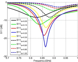
imaginary part of only 40 Ohms. Figure 5 shows that the Silicone layer has more influence on the real part than on the imaginary part of the input impedance. However, the loop length allows to adjust the imaginary part. Thus in the presence of the Silicone layer, a loop having a length of 13 mm and a width of 1 mm allows to increase the imaginary part close to the desired value but decreases at the same time the real part. That is why a dipole was added close to the loop to obtain a strong coupling and enhance the real part (Figure 3). This dipole contains two adjustable strands of length L1. The variation of the antenna impedance as a function of L1 is presented Figure 6. Nevertheless, as the size of the tag is limited to 26 mm due to the specifications of our application, we have folded the dipole along its length leading to an increase of the real part from 0.9 to 2.5 Ohms, for L1 = 12.5 mm (Figure 5(b)). Then two other strands of length L2 were added to increase the real part up to 3.5 Ohms (Figure 6(a)). This action allows the imaginary part to remain constant as shown (Figure 5(b) and Figure 6(a)). Finally, two metal plates of length L3 = 4.9 mm were designed on the other face of the substrate to couple with the upper radiating element. Moreover, two vias have been added to connect the upper and the lower metal plates to obtain the desired electrical length despite the small volume available. By this way, the real part has increased up to 5.5 Ohms (Figure 6(b)). The study on the influence of the Silicone layer thickness has thus shown that by choosing ts = 0.25 mm, the impedance matching
procedure was facilitated and the antenna efficiency was enhanced (Figures 5-6). These results can be explained the properties of the close environment of the antenna. Indeed, as the dielectric constant of the environment is high, the guided wavelength decreases. Equation (12) confirms that the decrease of the guided wavelength leads to an enhancement of the resistance value.
(a) (b)
Figure 5. Simulated at 868 MHz: (a) Loop impedance as function of its length Lloopfor Wloop=1 mm,
(b) Antenna impedance as function of the dipole length L1 for Lloop=13 mm.
Instead of calculating the matching efficiency as it is often the case for the antennas tag [30] and which only takes into account the impedance of the antenna and the chip, we have simulated under
(a) (b)
Figure 6. Antenna impedance at 868 MHz: (a) As function of the parameter L2 for L1=12.5 mm, (b) As function of the length L3 of the metal plates for L1 = 12.5 mm and L2 = 8.1 mm.
HFSS the radiated efficiency of our antenna which only takes into account the losses and which is independent of the impedance of the chip [31]. In Figure 7(a), the evolutions of the resonant frequency and the radiation efficiency of the antenna are plotted as a function of the thickness of the Silicone layer. We note that the efficiency is maximum (slightly greater than 0.75%) for a thickness equal to 0.8 mm at 913 MHz which is not the desired frequency. Moreover, if we consider the antenna efficiency at the resonance frequency (868 MHz), we observe that its value is maximum for an insulating layer thickness between 0.2 mm and 0.3 mm (Figure 7(b)). Moreover, we can also see that the insulation layer thickness has an important influence on the antenna matching (Figure 8).
(a) (b)
Figure 7. Simulation as a function of the insulation layer thickness ts: (a) Efficiency and resonance
frequency of the antenna, (b) Antenna efficiency at 868 MHz.
Based on these simulated results, the antenna has been optimized and its final dimensions are: Lloop = 13 mm, L1 = 25 mm, L2 = 6.1 mm and L3 = 4.9 mm are summarized in Table 4. For these
values, the antenna (loop and dipole) impedance is Zant = 6.3 + j74.2 Ohms.
Figure 9(b) is presented the simulated reflection coefficient calculated by using: S11 = Zant− Z
∗ chip
Zant+ Zchip
Figure 8. Simulated reflection coefficients as function of the Silicone isolation thickness ts (mm).
Table 4. Optimized antenna parameter dimensions.
Parameters Values (mm) Lloop 13.0 Wloop 1.0 L1 12.5 L2 8.1 L3 4.9 ts 0.25
We observe a good matching at the working frequency (868 MHz, BW = 70 MHz) and the total gain reaches a maximum value of -17.5 dBi (Figure 9(a)) which is greater than the minimum gain of -28.9 dBi previously calculated for the link budget (10). This gain value is acceptable considering the antenna dimensions and the other works previously presented in [15], [32]-[35]. Thus, the total antenna volume is only 30.5 mm3 which is small compared to similar implantable antennas operating at these frequencies and listed in Table 5. Thus, with this antenna, the received power by the reader Prx reader
can be between -55.2 dBm and -68.4 dBm for an emitted power of 27 dBm according to (1). These results confirm that the performance of the antenna is strongly influenced by the biocompatible insu-lating layer and the lossy tissue environment.
Table 5. Comparison of implantable antenna performance found in literature.
References Bande (MHz) Antenna Type Eff.(%) Gain (dBi) Volume (mm3)
[7] 868 Circular PIFA - -35.1 π x 62 x 1.8 = 203
[11] 868 Cylindrical Microstrip 2.75 - π x 52 x 55 = 4319
[29] 868 Loop 0.33 -28 π x 52 x 15 = 1178 [10] 868 Spiral PIFA - - 8 x 7 x 2 = 112 Proposed Antenna 868 Loop and Dipole 0.7 -17.5 2.4 x 24.5 x 0.5 = 30.5
(a) (b)
Figure 9. Simulated results of the implanted antenna with insulation layer: (a) Reflection coefficients, (b) Radiation pattern.
3.2. Experimental results
To validate our design, a prototype has been realized. Figure 10 shows the antenna prototype and the procedure for measuring its impedance with a Vector Network Analyzer (VNA) Rohde & Schwarz ZVM (10 MHz - 20 GHz). Simulated and measured reflection coefficients in the two cases are calculated using (14) and compared in Figure 11. A reduction of the bandwidth and a slight shift of the resonant frequency can be observed (Figure 11), with a value of S11 around -5 dB at 868 MHz. This is due to the manufacturing process which can introduce small variations on the insulation layer thickness as it was shown Figure 8.
Figure 10. Reflection coefficient measurement set-up.
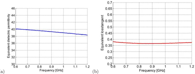
The measurements were done by connecting a small cable to the antenna [11], [32], which was then immersed in a body phantom realized by combining diethylene glycol butyl ether (44%) and de-ionized water (56%) [33], [16], in order to obtain the same permittivity as the homogeneous theoretical model used for the simulation. The solution is contained in a 60 ml polypropylene cylindrical flask having dimensions and shape close to those of the animal body. The equivalent dielectric permittivity and loss tangent of the homogeneous tissue have been characterized between 300 MHz and 3 GHz by using coaxial probe method with the Agilent Technologies E8361C PNA Network Analyzer. The material under test (MUT) has been measured at the Orange Labs laboratory site of Sophia Antipolis (France)
Figure 11. Reflection coefficient of the implanted antenna with Silicone layer.
as shown Figure 12. The coaxial probe is first calibrated at the terminal planes of probe by using Open-Short-Match calibration procedure [34]. The MUT characterization done by using coaxial probe method requires to carefully position the specimen in order to avoid air gaps or bubbles between the specimen liquid interface and the boundaries of coaxial probe that could affect the accuracy of measurement. Finally, the properties of the MUT relative permittivity can be calculated from PNA Network Analyzer measurement by using the Cole-Cole model [19]. The dielectric constant and the loss tangent results are shown in Figures 13(a) and (b). We observed that the properties values of the tissue model do not change too much in the frequency band of interest. Moreover, the trend of these curves corresponds to the results given by Gabriel and all in [17], [18].
Figure 12. Equivalent dielectric permittivity measurement set-up.
The implantable tag prototype has been tested with a RFID reader antenna connected to an Impinj Speedway Revolution R420 reader [35] allowing to receive the data from the implanted antenna associated to the Impinj Monza 4 chip as shown in Figure 14 (a). A computer including a softwareR
interface allowing us to control the whole system is connected to the reader (Figure 14 (b)). With these elements, the reader is able to detect the tag in the Plexiglas rack cage after few seconds. The reader antenna inspired from [36], is presented in Figure 15. It is made up of an annular ring slot, excited by a micro-strip line on the lower face of the substrate. The micro-strip/slot line transition is used in
(a) (b)
Figure 13. Measurement results of the equivalent homogeneous mouse tissue: (a) The equivalent dielectric permittivity, (b) The equivalent loss tangent.
combination with a small open circle stub for the matching. A U-shaped slot stub is also added to miniaturize the whole diameter of the antenna and to obtain the circular polarization usually required for UHF RFID reader antenna.
Figure 14. RSSI measurement: (a) Antenna prototype in the phantom model, (b) Measurement set-up.
The simulated and measured reflection coefficients of the reader antenna are given in Figure 16. We can see that the antenna is well matched in the UHF band with a S11 value around -13 dB at 868 MHz and that a good agreement is obtained between simulated and measured results.
Figure 16. Simulated and measured reflection coefficients of the reader antenna.
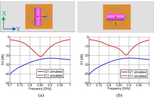
In order to verify that the implanted tag can be detected whatever its position in the cage, further simulated and measured cases were completed. First, the cage bottom was graduated along the X and Y axis in order to position accurately the phantom model (Figures 15 and 18). Figure 17 presents the simulated S parameters calculated for the configurations where the tag is disposed in the homogenous phantom model. This later is then placed at the cage bottom above the center of the reader antenna in two cases: the phantom model oriented along the X axis and along the Y axis. For both cases, we can see that the obtained values are around -23 dB for the transmission coefficient and around -20 dB for the reflection coefficient at 868 MHz.
Figure 17. Simulated reflection and transmission coefficients of the reader antenna at the positions of phantom model oriented along the X axis (a), the Y axis (b).
Then, these siumlated results have been compared to measurements. To know the operating distance of a tag, it is important to measure the backscattered signal which is the power level returned
Figure 18. Positions of phantom model oriented along the X axis (a), the Y axis (b) and varing according to the Y axis.
Figure 19. RSSI measurements when the phantom model is oriented along the X axis (a), and along the Y axis (b) versus the position of the phantom along the Y axis.
by the tag and received by the reader. That can be estimated by measuring the RSSI which is a parameter proportional to the level of the received power [37]. Figure 19 presents the measured values obtained for the two phantom orientations. As we can observe, the RSSI value is close to the maximum when the phantom model is above the center of the reader antenna. The small shift in the position compared to the center of the antenna is due to the asymmetry of the plastic casing of the phantom, the asymmetry of the reader antenna and uncertainties in the phantom positioning. The influence of this asymmetry is logically more important when the phantom is oriented along the Y axis than along the X one. According to Figures 19 (a) and (b), we can observe that the measured RSSI values are between -48 dBm and -68 dBm, which are close to the theoretical values calculated previously in section 2. These results demonstrate that our system can operate in a small and limited area of the cage. Thus, by placing several antennas in different zones of the cage, the system can detect and identify a small animal equipped with such miniaturized implanted tag.
4. CHARACTERIZATION OF E AND H FIELDS
Often implanted antennas powered by RFID chips are either dipoles whose dominating field is the electric field (E) or loop antennas with dominant magnetic fields (H). In this work, we used a dipole antenna coupled to a loop antenna. This allows to obtain a field E and H simultaneously dominant in the operating zone of the tag. To justify the performance of this antenna, we have also studied its radiating near fields as the shape of the E field and especially the one of the H field, which is of particular interest in the context of our application. Figures 20(a) and (b) represent the shape of these two fields as a function of the width and the length of the animal body phantom along the X axis and the Y axis. These electromagnetic fields were simulated at the height of the implanted tag in the homogeneous
model and are observed at 868 MHz. We can note that whatever is the direction of observation, the maximum of the two fields are obtained at the position corresponding to the center of the implanted antenna. The distribution of the fields along the X axis is narrower than that obtained along the Y axis, due to the geometry of the antenna. In addition, we can see that the H and E fields are concentrated around the tag and attenuated as we move away from the surface under consideration. The geometry of the antenna explains the observed results. Indeed, the radiating element is composed of a rectangular magnetic loop (dominant H-field) coupled to an electrical dipole (dominant E-field), that is why these two components are both present in the near-field antenna radiation zone.
(a) (b)
Figure 20. E and H standardized fields as a function of the width of the homogeneous model : (a) Along the X axis, (b) Along the Y axis.
5. CHARACTERIZATION OF SAR (SPECIFIC ABSORPTION RATE)
When an electromagnetic wave source is positioned near or placed within a biological medium, some of the radiated power is absorbed by the medium and may increase its temperature. The energy dissipated in a living body which produces localized heating or generates the heat stress can be quantified by calculating the SAR. The SAR parameter is expressed in Watt per kilogram (W/kg), and is defined as the ratio of the amount of power absorbed (dW ) by the mass unit (dm) of the tissue (15). For determining the SAR, we have to take into account the peak value of the electric field E induced in biological media at the working frequency, the electrical conductivity σ and the density ρm of the
medium (16). In the case of a short exposure duration, the SAR can be expressed from equation (17) as a function of the temperature variation ∆T , the exposure time ∆t and the specific heat Cm of the lossy medium [38], [39]. SAR = dW dm (15) SAR = σ 2ρm |E|2 (16) SAR = Cm ∆T ∆t (17)
It is generally agreed that if the SAR value is too high, the transmitted power is low. Figure 21 shows the SAR10-g distribution around the antenna. This simulation aims at characterizing the thermal elevation in biological media exposed to electromagnetic waves. Indeed, the simulated results denote that the SAR10-g maximum value observed at 868 MHz is 1.31 W/kg (in the case of a Silicone thickness of 0.25 mm and a maximum supply power of 500 mW) which corresponds to the maximum allowed standard guideline in Europe (2 W/kg averaged over 10-g of tissue) [40], [41]. Figure 22 shows the simulated 10-g average SAR maximum values at 868 MHz as a function of the insulation layer thickness by using CST software which gives us more options for simulating this parameter. As depicted in this
figure, the results show that the use of the insulation layer allows to improve the efficiency and reduce the SAR10-g value in the tissue environment. Furthermore, it validates again that the best choice for the Silicone thickness is in the 0.2 mm to 0.3 mm range as mentioned in the section 3.
It is well known that of passive tags, the RFID reader supplies the power to activate the tag. A simulation close to this use case was done by using the reader antenna presented in the 3.2 section. This latter was located under the cage bottom and was fed by 500 mW. The result shows that the SAR10-g maximum value is 0.447 W/kg (Figure 23) which respects the safety regulation rules. The same simulations have been done with HFSS software. The obtained results are very close : around 1.4 W/kg for the case presented Figure 21 and 0,44W/kg for the one presented Figure 23. However, for brevity only CST results are presented.
Figure 21. SAR10-g distribution at 868 MHz in the case of ts = 0.25 mm insulation layer thickness.
Figure 22. Simulated SAR10-g maximum values at 868 MHz as a function of the insulation layer thickness ts.
6. CONCLUSION
In this paper, the design of an implanted antenna intended to operate in the European UHF RFID band was presented. The antenna consists in a printed dipole excited by a loop associated to a RFID chip. Techniques for improving its efficiency and miniaturization have also been proposed. The optimized antenna presents a radiation efficiency of 0.7% and a total gain of -17.5 dBi. A homogeneous body phantom was used for the simulations and the measurements. The observation of the electromagnetic near fields radiated by the implanted antenna has validated the presence of the two fields components
Figure 23. Simulated SAR10-g maximum values at 868 MHz with the presence of the reader antenna placed under the cage.
due to the geometry of the structure thus facilitating the implanted tag detection by the reader. RSSI measurements have also demonstrated the possibility of reliable wireless communications between the implanted antenna and an external reader. Finally, the SAR10-g distribution has been evaluated and the results have shown that the antenna respects the safety requirements and may be used in the intended application.
ACKNOWLEDGMENT
This work was partly funded by the French Government (National Research Agency, ANR) through the “Investments for the Future” Program reference #ANR-11-LABX-0031-01. The authors would like to thank also the CREMANT for its support on the measurement part.
REFERENCES
1. R. S. M. and B. Jacobson, “Endoradiosonde,” Nature, vol. 179, pp. 1239-1240, 1957.
2. W. A. Qureshi, “Current and future applications of the capsule camera,” Nature Rev. Drug Disc., vol. 3, no. May, pp. 7-10, 2004.
3. F. Merli, B. Fuchs, J. R. Mosig, and A. K. Skrivervik, “The effect of insulating layers on the performance of implanted antennas,” IEEE Trans. Antennas Propag., vol. 59, no. 1, pp. 21-31, 2011.
4. A. Karlsson, “Physical limitations of antennas in a lossy medium,” IEEE Trans. Antennas Propag., vol. 52, no. 8, pp. 2027-2033, 2004.
5. C. M. Furse and A. Chrysler, “A History & Future of Implantable Antennas,” in IEEE Antennas and Propagation Society International Symposium (APSURSI), pp. 527-528, 2014.
6. A. Kiourti, K. A. Psathas, and K. S. Nikita, “Implantable and ingestible medical devices with wireless telemetry functionalities: A review of current status and challenges,” Bioelectromagn. Wiley Period. Inc., vol. 35, no. 1, pp. 1-15, 2014.
7. A. Kiourti and K. S. Nikita, “Miniature scalp-implantable antennas for telemetry in the MICS and ISM bands: Design, safety considerations and link budget analysis,” IEEE Trans. Antennas Propag., vol. 60, no. 8, pp. 3568-3575, 2012.
8. L. Catarinucci, R. Colella, L. Mainetti, V. Mighali, L. Patrono, I. Sergi, and L. Tarricone, “Near Field UHF RFID Antenna System Enabling the Tracking of Small Laboratory Animals,” Int. J. Antennas Propag., vol. 2013, pp. 1-10, 2013.
9. R. Bakore, J. C. West, C. Hutchens, and R. Ahmed, “Design of a proposed folded dipole antenna for use with an implantable RFID tag at 915 MHz,” in 2013 IEEE Antennas and Propagation Society International Symposium (APSURSI), Orlando, FL, USA, 2013, pp. 2085–2086.
10. A. Garcia-Miquel, B. Medina-Rodr´ıguez, N. Vidal, F. M. Ramos, E. Roca, and J. M. Lopez-Villegas, “Design and characterization of a miniaturized implantable UHF RFID tag based on LTCC technology,” in 11th European Conference on Antennas and Propagation (EUCAP), pp. 1024-1026, 2017.
11. A. Dubok and A. B. Smolders, “Increased Operational Range for Implantable UHF RFID Antennas,” 8th Eur. Conf. Antennas Propag. (EuCAP 2014), pp. 1749-1753, 2014.
12. J. M. Jeevani, W. Jayasinghe and Disala Uduwawala, “A Novel Multiband Miniature Planar Inverted F Antenna Design for Bluetooth and WLAN Applications,” International Journal of Antennas and Propagation, pp. 1–6, 2015.
13. A. K. Skrivervik, “Implantable antennas: The challenge of efficiency,” in 7th Eur. Conf. Antennas Propagation, EuCAP 2013, pp. 3627-3631, 2013.
14. M. Rodriguez, C. Furse, and R. Franklin, “Manufacturing considerations for implantable antennas,” IEEE Antennas Propag. Soc. AP-S Int. Symp., pp. 2087-2088, 2013.
15. V. H. Nguyen, A. Diallo, P. Le Thuc, R. Staraj, S. Lanteri, G. F. Carle, “Wireless interrogation of small animal phantoms with a miniature implanted UHF RFID tag,” in Antenna Measurements & Applications (CAMA), IEEE International Conference, vol. 3, pp. 306-309, 2017.
16. T. Karacolak, R. Cooper, and E. Topsakal, “Electrical properties of rat skin and design of implantable antennas for medical wireless telemetry,” IEEE Trans. Antennas Propag., vol. 57, no. 9, pp. 2806-2812, 2009.
17. S. Gabriel, R. W. Lau, and C. Gabriel, “The dielectric properties of biological tissues: III. Parametric models for the dielectric spectrum of tissues,” Phys. Med. Biol., vol. 41, no. 11, pp. 2271-2293, 1996.
18. C. Gabriel, “Compilation of the dielectric properties of body tissues at RF and microwave frequencies,” Report Documentation, Dept of Physics AFOSR-TR-96 King’s College London, UK, 1996.
19. M. Lazebnik, M. Okoniewski, J. H. Booske, and S. C. Hagness, “Highly Accurate Debye Models for Normal and Malignant Breast Tissue Dielectric Properties at Microwave Frequencies,” IEEE Microw. Wirel. Components Lett., vol. 17, no. 12, pp. 2007-2009, 2007.
20. P. Perrissol, M. Monedero, R. Ndashymie, A. Diallo, P. Le Thuc, R. Staraj, G. F. Carle, “Wireless interrogation of an implanted temperature sensor in a mouse,” in Proceed. IEEE International Conference on RFID-Technologies and Applications (RFID-TA), pp. 52-55, 2012.
21. ERC Recommendation (70-03) [Online]. Available:
http://www.erodocdb.dk/docs/doc98/official/pdf/rec7003e.pdf
22. C. A. Balanis, Antenna Theory: Analysis and Design, 3rd Edition. Wiley, 2015.
23. K. Fujimoto and H. Morishita, Modern Small Antenna, Cambridge University Press, 2013. 24. H. G. Schantz, “A Near Field Propagation Law & A Novel Fundamental Limit to Antenna Gain
Versus Size,” IEEE APS Conf., vol. 2, no. July, pp. 4-7, 2005.
25. S. J. Orfanidis, Electromagnetic Waves and Antennas. Prentice-Hall, 2003.
26. Monza 4 RFID Impinj chip datasheet [Online]. Available: https://support.impinj.com/hc/en-us/articles/202756908-Monza-4-RFID-Tag-Chip-Datasheet.
27. D. M. Dobkin, The RF in RFID, Second Edition: UHF RFID in Practice, 2 edition. Amsterdam: Newnes, 2012.
28. Y.-P. Luh and Y.-C. Liu, “Measurement of Effective Reading Distance of UHF RFID Passive Tags,” Mod. Mech. Eng., vol. 03, no. 03, pp. 115-120, 2013.
29. T. Karacolak, R. Cooper, J. Butler, S. Fisher, and E. Topsakal, “In vivo verification of implantable antennas using rats as model animals,” IEEE Antennas Wirel. Propag. Lett., vol. 9, pp. 334-337, 2010.
Antenna for Use with an Implantable RFID tag at 915 MHz,” Antennas and Propagation Society International Symposium (APSURSI), pp. 2085–2086, 2013.
31. Galehdar, Amir, Thiel, David V, O’Keefe, Steven G, “Antenna efficiency calculations for electrically small, RFID antennas,” IEEE Antenna and Wireless Propagation Letters, 2007.
32. R. S. Alrawashdeh, Y. Huang, M. Kod, and A. Abu Bakar Sajak, “A Broadband Flexible Implantable Loop Antenna With Complementary Split Ring Resonators,” IEEE Antennas Wirel. Propag. Lett., vol. 14, pp. 1322-1325, 2015.
33. P. Perrissol, A. Diallo, P. Le Thuc, R. Staraj, and G. F. Carle, “Performance of a cross dipole antenna dedicated to biological telemetry,” in The 8th European Conference on Antennas and Propagation (EuCAP 2014), pp. 2174-2177, 2014.
34. Agilent 85070E Dielectric Probe Kit [Online] Available: http://na.support.keysight.com/materials/help/85070.pdf.
35. RFID Impinj Speedway Revolution R420 reader [Online]. Available:
https://support.impinj.com/hc/en-us/articles/202755358-Speedway-Revolution-Installation-Operations-Guide
36. C. Phatra and P. Krachodnok, “A circularly polarized antenna for UHF RFID reader,” in 11th International Conference on Electrical Engineering/Electronics, Computer, Telecommunications and Information Technology (ECTI-CON), pp. 1-4, 2014.
37. B. G. Lee and W. Y. Chung, “Multitarget Three-Dimensional Indoor Navigation on a PDA in a Wireless Sensor Network,” IEEE Sens. J., vol. 11, no. 3, pp. 799–807, Mar. 2011.
38. C. Liu, Y.-X. Guo, and S. Xiao, “A review of implantable antennas for wireless biomedical devices,” in Forum for Electromagnetic Research Methods and Application Technologies (FERMAT), 2016. 39. N. Othman, N. A. Samsuri, M. K. A. Rahim, and N. A. Elias, “SAR in the Presence of Conductive Medical Implant At 0.9, 1.8 and 2.4 GHz Due to Close Proximity Antenna,” 10th Eur. Conf. on Antennas Propag. (EuCAP), pp. 8-12, 2016.
40. Y. Zhao, R. L. Rennaker, C. Hutchens, and T. S. Ibrahim, “Implanted miniaturized antenna for brain computer interface applications: analysis and design,” PloS One, vol. 9, no. 7, p. 1-10, 2014. 41. IEEE Standards Coordinating Committee, IEEE C95. 1-2009: IEEE Standard for Safety Levels with Respect to Human Exposure to Radio Frequency Electromagnetic Fields, 3 kHz to 300 GHz, April. 2006.