HAL Id: cea-02400171
https://hal-cea.archives-ouvertes.fr/cea-02400171
Submitted on 9 Dec 2019
HAL is a multi-disciplinary open access
archive for the deposit and dissemination of
sci-entific research documents, whether they are
pub-lished or not. The documents may come from
teaching and research institutions in France or
abroad, or from public or private research centers.
L’archive ouverte pluridisciplinaire HAL, est
destinée au dépôt et à la diffusion de documents
scientifiques de niveau recherche, publiés ou non,
émanant des établissements d’enseignement et de
recherche français ou étrangers, des laboratoires
publics ou privés.
Innovating leak detection on conducting fluid pipelines
M. Girard, S. Albaladejo, P. Charvet, S. Lusso, S. Armiroli, G. Laffont, R.
Cotillard
To cite this version:
M. Girard, S. Albaladejo, P. Charvet, S. Lusso, S. Armiroli, et al.. Innovating leak detection on
con-ducting fluid pipelines. I2MTC (International Instrumentation and Measurement Technology
Confer-ence), May 2018, Houston, United States. �cea-02400171�
Innovating leak detection on
conducting fluid pipelines
M. Girard, S. Albaladejo, P. Charvet, S. Lusso,*S. Armiroli, *G. Laffont, *R. Cotillard
CEA (French Commission for Atomic and Alternative Energies) Saint Paul Lez Durance, France
*Paris, France marianne.girard@cea.fr
Abstract - CEA (French Commission for Atomic and Alternative Energies) has launched a R&D program focused on leak detection of sodium on industrial ducts aiming at detecting and pinpointing the exact location of fluid leakage along pipelines or on tanks quickly. This R&D program is focused on the development of innovating detectors, Multilayer-type and Optical Fiber Distributed Sensors, involving tests on mock-ups in a dedicated sodium loop settled at CEA-CADARACHE, France. This loop named FUTUNa, is designed to produce very accurate sodium leak rates within a range around 1 cm3/min, the tests
being performed at various temperatures (from 180°C up to 550°C) on large-diameter pipe mock-ups (DN 800) under ambient or nitrogen environment.
This paper presents the advantages of each innovating detector and series of tests carried out with various materials of the Multilayer-type Detector and different routings of the Optical Fiber Sensor. The relevant results are compared and discussed as well as the observations made after removing the mock-ups. The most interesting result of the overall tests is a rapid detection time for the two types of detectors less than the other conventional wire type leak detection systems.
Item: In-service inspection - leak instrumentation - conductive fluid - pipeline - duct - storage tank - electrical short circuit - multilayer detector system - optical fiber sensor
I. INTRODUCTION
CEA (French Commission for Atomic and Alternative Energies) has launched a R&D program focused on low leak rates detection of liquid sodium on pipes within the framework of the ASTRID reactor project (Advanced Sodium Technological Reactor for Industrial Demonstration). For safety reasons and to avoid any corrosion process between sodium and materials of the pipes or tanks (e.g stainless steel), any sodium leak has to be detected early. Mainly due to some unreliability of the Na leak detection systems previously used on Na reactor pipes [1] [2], this CEA program is focused on the development of two innovating detector systems: the Multilayer Detector and the Optical Fiber Sensor involving different operating principles.
A testing program has been proposed in year 2011 by the Nuclear Energy Division (DEN) of CEA for the development of the Multilayer Detector technology including tests undertaken in a sodium loop at CEA, Cadarache, France. This
relevant FUTUNa loop allows operating at various temperatures up to 550°C with very accurate sodium leak rates within the range [0.05-30 cm3/min]. The tests were conducted with different pipe mock-ups including the two detector systems under study. The Rayleigh Backscatter C-OFDR (Coherent-Optical Frequency Domain Reflectometry) Technology is developed for this application since 2012 by the Technological Research Division (DRT) at CEA, Saclay, France. Their contribution is to select the adapted sensor and parameters for detection and to develop an intelligent software insuring measurement reliability through calibrated O.F sensors and fast treatment.
This paper presents the progress of the detector developments providing results of the FUTUNa tests which were undertaken within different material layers and various O.F layings on mock-ups. The overall results are discussed and the status on the ongoing R&D studies is presented.
II. THE TWO INNOVATING Na LEAK DETECTION SYSTEMS
The two relevant detectors have been identified on first for uses on specific circuits of the ASTRID reactor and for a [100-800 mm] diameter range of pipes. Until now they are considered as two complementary detector systems for SFR (Sodium-cooled Fast Reactor) circuits.
II.1 Description and principle of the Multilayer Detector Its principle (see Fig.1) is based on the loss of electrical insulation between an ionized liquid (e.g sodium) and an electrically conductive layer covering a component as duct, pipeline or storage facilities.
Fig. 1: Principle and schematic design of the Multilayer Na leak Detector patented by CEA [3]
The electrical properties of the medium will close the detection circuit which, in turn, will trigger an alarm. As described in the CEA patent [3], the design of this innovating Multilayer Detector is as follows. The component (here a pipe) is totally covered with:
- Layer (1): an electrically insulating layer constituted by insulating fibers of silica oxides (or aluminum, magnesium or calcium oxides);
- Layer (2): an electrically conductive layer constituted by carbon, graphite or stainless steel;
- Layer (3): a thermally insulating layer constituted by silica oxides;
- an overall mounting protection made of galvanized steel sheet.
The up-dated advantages of the Multilayer Detector for ionized liquid leak detections can be listed below:
- high fiability avoiding problems of triggered “false alarms”;
- precise location of the leak within the implementation of dedicated sections (≤ 10 linear meters) along pipes; - shorter detection time than wire type leak detectors for
low leak rates of sodium (QNa < 10 cm3/min) and for a
[350-550°C] temperature range. Wire type leak detectors made of steatite beads are largely used for SFR (Sodium Fast Reactor) circuits and components [4] [5].
II.2 Description of the Optical Fiber Sensor
The relevant C-OFDR technology is based on a frequency analysis of the Rayleigh backscattered light along the core of the optical fiber [6]. Collecting and processing this backscattered signal, an OFDR trace is obtained and distributed along the length of the optical fiber’s core. Thus for the relevant application, the O.F is used as a distributed temperature transducer and the temperature change can be followed in quasi real time over a predefined segment of the optical fiber (Lmax.= 100 m). Any leak of Sodium, leading to a localized increase in temperature, is detected as a “hot spot” along a reference temperature profile of the pipe. A calibration in temperature is required in order to get an absolute temperature measurement, and especially when working at several hundred of degree Celsius.
Rayleigh reflectometry for distributed optical fiber-based leak detection has been chosen by CEA [7] as it gives sufficient resolution (~ mm) to measure temperature profile up to 70 m in length. Careful choice of temperature detection threshold above the pipe temperature and specific processing algorithms are mandatory to remove numerical artifacts and thus avoid false alarms.
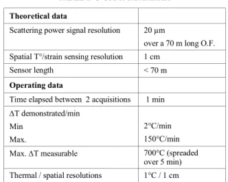
A gold-coated single mode optical fiber was installed at CEA to perform detection tests of liquid sodium leakage on a pipe mock-up in 2012 [8]. Since that date, further experimental tests have been conducted in order to improve the relevant technology. The capabilities and operating data of the relevant Rayleigh reflectometry technology as detailed in [7] are summarized in Table I.
TABLE I. C-OFDR CAPABILITIES
Theoretical data
Scattering power signal resolution 20 µm
over a 70 m long O.F. Spatial T°/strain sensing resolution 1 cm
Sensor length < 70 m
Operating data
Time elapsed between 2 acquisitions 1 min T demonstrated/min
Min
Max.
2°C/min 150°C/min Max. T measurable 700°C (spreaded
over 5 min) Thermal / spatial resolutions 1°C / 1 cm
Note that the Au coating has been selected regarding its 700 °C maximum operating temperature, the polyimide and Cu coatings allowing to operate at lower values (300 and 600°C respectively).
At present time, CEA considers that single mode O.F are candidates for instrumentation for leak detection due to:
- low intrusive effects and free of electromagnetic interferences;
- reliability at high temperature ranges, even when operating in harsh environments;
- accurate spatial localization of the leak along the O.F routing on the pipe (sensor routing over several tens of meters);
- 1°C temperature resolution with 1 cm spatial resolution, fast response time.
III. THE TESTING PROGRAM AND TOOLS
III.1 The testing program
A testing program taking into account the maturity of each innovating system has been drawn up at CEA since 2011 within the following task forces:
The CEA List LCAE (Sensors and Electronics Laboratory) conducts its own R&D testing program on the O.F and is involved by the signal processing during the overall tests on mock-ups.
The study and selection of the multilayer materials are conducted by the CEA LIET (Instrumentation and Technological Testing Laboratory) within the steps detailed in Fig. 2.
The program sequence involving the two laboratories is described on Fig. 2 hereafter. The 5th and last step is related to
a final status after removing the mock-ups of the FUTUNa loop. The optical fiber sensor is integrated right from step 3 for the Na leak tests on mock-ups.
Note that the “Chemical compatibility” of Step 1 is measured by means of micro-gas chromatography (µGC) and Differential Scanning Calorimetry (DSC).
Fig. 2: CEA R&D testing program for the Multilayer Detector and Optical Fiber sensor dedicated to ionized fluid leak detection on pipes
The “Na permeability” of Step 2 is evaluated within a dedicated mounting placed in an argon glove-box with appropriate analyses performed after the test.
The nominal parameters required for step 4 (i.e Na leak tests on mock-ups within the FUTUNa loop) are totally linked to the ASTRID reactor concept and their up-dated values are given in Table II below. One other major point is that the relevant nominal Na leak rate belongs to the [1-10 cm3/min] range
which corresponds to the more penalizing configuration for leak detections.
These nominal values and ranges have been taken into account as much as possible to set the Step 1 and Step 2 experiments dedicated to the Multilayer Detector development.
III.2 The FUTUNa facility
The FUTUNa loop has been chosen because it is designed to produce very accurate sodium leak rates within a range between 0.05 and 30 cm3/min. Furthermore it has an experiment area equipped with an extraction hood in which different types of mock-ups can be installed. The current outlines of the loop are presented in Fig. 3 with the picture of one mock-up.
The pipe: the tests are performed on a 2m-long pipe made of 316L stainless steel which is horizontally positioned with a slope of 3%. It is equipped with two 1m-long heating cores to simulate the sodium temperature inside the pipe. The sodium injection is realized in the upper part of the pipe by means of an injection line.
TABLE II. NOMINAL PARAMETERS REQUIRED FOR Na LEAK TESTS ON MOCK-UPS
Parameters Nominal values or ranges Na leak rate 1 cm3/min
Detection time ≤ 10 hours
Na temperature 180°C ≤ TNa ≤ 550°C Pipe diameter 100 ≤ O.D ≤ 700 mm Environment ambient air, inert
Operating principle: the sodium contained in the storage tank (150 L) is heated until it reaches its liquefaction temperature. This sodium is then pumped by an immersed electromagnetic pump so as to fill a loading tank. In this configuration, the test can be conducted with 2 piston pumps (flow rate between 0.05 and 2 cm3/min) by continuously injecting the sodium into the test mock-up at the required rates. The Na injection line is equipped with several thermocouples up to the “Na injector outlet” which is a 6 mm-conical leak hole (see Fig. 4).
Test principle: Test section and sodium injection line are preheated at the nominal parameter of the test. Piston pumps are operated and checked for its operation and performance. The electrically conductive second layer (2) of the Multilayer Detector is tested for leak indication before conducting the experiment by short circuiting.
The test is considered to start at the time that a spark plug Na-leak detector positioned at the injector outlet indicates when sodium leaks on the external surface of the pipe. The test ends if the electrically conductive second layer (2) triggers the alarm. If not, the injection pump is manually stopped after 10 hours or 24 hours for tests undertaken at low temperatures (TNa ~ 200°C). The Na circuit is then drained, all heaters are switched off and the facility is cooled to room temperature to allow the complete removing of the mock-up the day after.
Fig. 3: Schematic diagram of the FUTUNa-2 loop with picture of a lagged pipe mock-up (OD: 800 mm)
1 - Chemical compatibility between 1rst layer and ionized fluid 2 - Ionized fluid permeability of the 1rst layer 3 - From design to realization of the mock-up 4 - Leak test on mock-up within the FUTUNa loop 5 - Final status after removing
the mock-up Optical Fiber
sensor and Multilayer Detector
Fig. 4: Instrumentation and Optical Fiber sensor layout on the pipe (800mm-OD) before mounting the Multilayer Detector
The mock-up mounting, the FUTUNa tests and the removal of the mock-ups are conducted by the appropriate personnel of the LIET as well as the glove box tests of Step 2.
III.3 The mock-up
The dedicated pipe is equipped with the two detectors in study and instrumentations as follows.
Instrumentation: the Na expansion is monitored through 1 mm-OD (Outer Diameter) “skin temperature” thermocouples on the pipe as can be seen on Fig. 4. According to the objective of the tests, some wire type leak detectors are implemented on specific parts of the pipe and on the external lagging layer (3). The dedicated instrumentation is detailed in [9].
Optical Fiber Sensor: it is a gold-coated single mode fiber which is inserted in a 1 mm OD stainless steel tube to avoid any damages. The sensor is disposed directly on the pipe and even inside layer (1) if the fiber length in study allows it. An example of a helical pattern along the pipe, corresponding to a potential further industrial routing on reactor pipes, is shown on Fig.4. The length under study is at least of 12 m.
Multilayer Detector: the selected materials belong to
- insulating fibers of silica oxides (or aluminum, magnesium or calcium oxides) for layer (1)
- carbon, graphite or stainless steel for layer (2);
- insulating material mostly made of silica oxides (named Rock wool) for layer (3). This material is certificated as PMUC (French acronym of “Products and Equipments suitable for use in Nuclear power plants”).
The choice for the material of the 1rst layer was made as a
result of feedback from Step 1 and Step 2 of the CEA testing program (see Fig.2). Note that corrosion phenomena can occur on the pipe surface close to the Na leak area under this 1rst
material layer. This particular point have to be further studied, since a corrosion resistance is required for the overall mounting.
TABLE III. FUTUNA TESTS ON PIPE MOCK-UPS EQUIPED WITH MULTILAYER DETECTOR AND OPTICAL FIBER SENSOR
IV. TESTSRESULTS
Table III presents the results of two series of tests undertaken on mock-ups on the FUTUNa loop since 2012. The thickness and material of each layer of the Multilayer Detector as well as the specifications of the OF sensor are indicated. The overall testing are conducted in normal atmospheric conditions on 316 L stainless steel pipes whose outer diameters are in a [350 - 800 mm] range. The last column of the Table gives the Na injection duration time at which the electrically conductive layer (2) of the Multilayer Detector triggers the alarm.
IV.1 Observations and O.F measurement data
To illustrate a “positive Multilayer Detector result”, Fig.5 presents some views related to the test performed at 550°C for which detection occurred after 12 minutes of Na injection at 1 cm3/min-leak rate (see test TA550 in Table III). The impact
of the 12 cm3 of Na can be observed nearby the injector outlet
area on the pipe, through the thickness of the 1rst layer (30
mm-thickness) and on the 2nd detector layer. The affected area
covers approximately 150 x 100 mm of the pipe surface. A slight color change can be observed on layer (2), close to the injector outlet location, meaning that the detector layer may have reached locally its maximum operating temperature (i.e. 650°C) during this test.
Na injector outlet Skin thermocouples Optical Fiber wire leak detector
Fig.5 - TA550 test: Na reaction products on the pipe and layers (alarm of the Multilayer Detector after tleak = 12 min)
Fig. 6 - After PRG550 test: aspects of the pipe and layer1 after 8 hours of Na injection (no triggered alarm of the multilayer detector after tleak = 8 h)
Fig. 6 illustrates the PRG550 test performed at 550°C for which no detection within the Multilayer Detector occurred after 8 hours of Na injection whereas interesting measurements were obtained within the OF sensor. The detector layer has not been reached by the sodium and it turns out that all the injected volume (480 cm3) has been trapped
within the first 30 mm of the 150 mm-lagging layer (1). The affected area covers here approximately 200 x 200 mm of the pipe surface.
For this PRG550 test, the Optical Fiber sensor which is a 24m-length Au-coated type, is helicoidally wrapped around the pipe and layer (1) as described on Fig. 7. This deployment allows the monitoring of both the Na leakage detection on the pipe and the Na flow front on layer (1) through spatially-resolved temperature change measurements. Early temperature changes were observed on the pipe within the first minutes of Na injection at L = 38, 40 and 42 m, i.e. close to the Na outlet injector, whereas temperature changes were visualized on layer (1) after a 1h43min-injection duration time. Note that this O.F has not been damaged by direct contact with liquid sodium during the test.
Fig. 7 - PRG550 FUTUNa test: Optical Fiber Sensor signals on pipe and 1rst layer after tleak = 10min and 2h20min at 550°C
Fig.8 - MG200 FUTUNa test: Optical Fiber Sensor signal on pipe after tleak = 2h54min at 200°C
For the MG200 test performed at TNa = 175°C, the Optical Fiber sensor which was a 12m-length Au-coated type was helicoidally wrapped around the pipe as described on Fig.8. Temperature changes of ~ 10°C were observed after 1 hour of Na injection at L = 23.5, 26 and 28.5 m. Their intensities rise up to a few tens of °C after ~ 3 hours of Na injection as can be observed on the data of Fig.8.
IV.2 Status of the first series of mock-up tests
The first FUTUNa tests including the observations made after removing the mock-ups have led for each material layer and for the Optical Fiber sensor to the following synthesis. Layer (1)
S: interesting mock-up test results (detection time < 67 min) but this material will be replaced for further testing with a similar SiO2-based material belonging to PMUC, see layer 1 of the next PRG550 test ;
T: interesting mock-up test results (detection time < 49 min) and material qualified for corrosion resistance but industrial-scale production in rigid board forms that does not fit with the needs.
Layer (2)
G: positive mock-up test results but its use imposes a limit on the maximum operating temperature of 350°C under air at the 1rst/2nd layer interface;
A: positive mock-up test results but oxidation processes have been observed on this felt material after removing the mock-ups for tests undertaken at 550 and 350°C. Additional tests performed in furnaces have led to the same conclusions with the loss of the electrical properties due to corrosion process. O.F sensor
The first O.F sensor routing as an Archimedean spiral demonstrates that the resolution and precision of the instrumentation is sufficient to identify accurately the location of the leakage and its expansion on the pipe surface, providing 1°C temperature resolution with 1 cm spatial resolution [7]. Pipe
1rst layer
d (170 mm on the pipe)
T variation (in °C)
O.F length (in m)
IV.3 Status of the second series of mock-up tests Layer (1)
M: interesting mock-up test result with a 30 mm-layer thickness at 550°C but negative result at 200°C, high cost compared to other materials that would be a penalizing criterion ;
PR: belongs to PMUC but negative mock-up test result with a 150 mm-layer thickness at 550°C;
P: negative mock-up test result with a 65 mm-layer thickness at 200°C.
Layer (2)
A material with a higher upper operating temperature limit under air (350°C for G material) would allow reducing the layer (1) thickness and thereby ensuring the Na flux to pass through this thinner 1rst layer around the pipe.
O.F sensor
Helicoidal routings of the O.F sensor that corresponds to a potential further industrial routing on pipes, lead to interesting testing results with the experimental proof of concept in the [200-550°C] temperature range. The data are monitored, processed and displayed in real time as a localized temperature change along the O.F length allowing the determination of a helicoidal pitch of 400 mm for 600-800 mm outer diameter pipes. Results show a possibility to detect a flux of sodium leakage with or without any direct contact with the fiber, providing in a near future a 3D cartography of the expansion of the fluid around a pipe.
V. CONCLUSION
Leak tests of ionized fluid have been performed with two innovating detectors developed by CEA, the Multilayer-type and the Optical Fiber sensor. The testing campaign involves Na leak tests on pipe mock-ups connected to a dedicated facility, the FUTUNa loop settled at CEA-CADARACHE, France.
These experiments have led to interesting results with an experimental proof of concept at high temperature (350 ≤ T ≤ 550°C) for the Multilayer Detector, allowing to pinpoint the exact location of ionized fluid leakage along pipelines. An industrial application of the Multilayer Detector would be done within the implementation of dedicated sections along pipelines.
The use of Rayleigh-based reflectometer and single mode gold-coated optical fiber sensor routed in a helicoidal pattern on a pipe, have demonstrated that the leak flux is early detected and can be displayed as a localized temperature change along the optical fiber’s length for the overall operating temperature range of the tests, 180 ≤ T ≤ 550°C. Optical fiber routing is flexible and can be adjusted to any type of pipe diameters and components design, providing high thermal and spatial resolutions and a cartography of the fluid expansion on pipes in a near future.
ACKNOWLEDGMENT
The authors are thankful to S. Serbout (Master student in
Instrumentation Systems at Marseille University, France) and D. Cambet who took part in the FUTUNa experimental testing
program.
REFERENCES
[1] J. Guidez, “PHENIX, the experience feedback” edp sciences, April 2013 [2] J. Guidez, G. Prêle “SUPERPHENIX-Technical and Scientific
Achievements” Atlantis Press, January 2017
[3] S. Albaladejo, R. Zanolin, “Leak detection device and coating intended for a fluid transport or storage member and comprising said section device” CEA Patent 2010/03573, International Publication WO 2012/032233 A1
[4] V. Vijayakumar, S. C. Chetal, K. Madhusoodanan, C. Paramasivan Pillai, M. Sakthivel and Uma Seshadri, “ Sodium and steam generator leak detection for prototype Fast Breeder Reactor (PFBR)”, 12th International Conference on Nuclear Engineering (Volume 2) - April 25-29, 2004, Arlington, Virginia, USA - ICONE12-49362
[5] V. Vijayakumar, S. Chandramouli, B.K. Nashine, P. Selvaraj, K.K. Rajan “Experiments in LEENA facility with modified wire type leak detector layout in large sodium pipelines” Annals of Nuclear Energy 103 (2017) 326–333
[6] M. Froggatt and J. Moore, “High resolution strain measurement in optical fiber with Rayleigh scatter,” Applied Optics, vol. 37, pp.1735-1740, 1998.
[7] S. Armiroli, R. Cotillard, G. Laffont, M. Girard, D. Cambet, JPh. Jeannot, P. Charvet, S. Albaladejo, S. Lusso ”Sodium leakage detection for SFR reactors using Rayleigh backscatter OFDR technology”, ANIMMA 2017, 105 - International Conference on Advancements in Nuclear Instrumentation Measurement Methods and their Applications, June 19-23, 2017, Belgium.
[8] E. Boldyreva, R. Cotillard and al., “Distributed temperature monitoring for liquid sodium leakage detection using OFDR-based Rayleigh backscattering”, Proceeding 9157, 23rd International Conference on Optical Fibre Sensors, June 2014, Spain.
[9] M. Girard, S. Albaladejo, D. Cambet, S. Armiroli, R. Cotillard, G. Laffont, O. Carra, G. Prêle “Development of innovating Na leak detector on pipes”, FR17-273 - International Conference on Fast Reactors and related fuel cycles, June 26-29, 2017, Yekaterinburg, Russian Federation
![Fig. 1: Principle and schematic design of the Multilayer Na leak Detector patented by CEA [3]](https://thumb-eu.123doks.com/thumbv2/123doknet/12988222.378972/2.892.459.839.864.1035/fig-principle-schematic-design-multilayer-leak-detector-patented.webp)