Autonomous Powered Exoskeleton to Improve the
Efficiency of Human Walking
by
Luke Matthewson Mooney
B.S.,
Massachusetts Institute of Technology (2012)
S.M., Massachusetts Institute of Technology (2014)
Submitted to the Department of Mechanical Engineering
in partial fulfillment of the requirements for the degree of
Doctor of Philosophy
at the
MASSACHUSETTS INSTITUTE OF TECHNOLOGY
February 2016
@
Massachusetts Institute of Technology 2016. All rights reserved.
Signature redacted
Author ...
....
..
A o Department of Mechanical Engineering
Signature redacted
January 21, 2016
Certified by -...
Hugh M. Herr
Associate Professor
Thesis Supervisor
Signature redacted
Accepted by ...
...
Rohan Abeyaratne
MASSACHUSETTS
INSTITUTEChairman,
Committee
on Graduate
Students
OF TECHNOLOGY
Autonomous Powered Exoskeleton to Improve the Efficiency
of Human Walking
by
Luke Matthewson Mooney
Submitted to the Department of Mechanical Engineering on January 21, 2016, in partial fulfillment of the
requirements for the degree of Doctor of Philosophy
Abstract
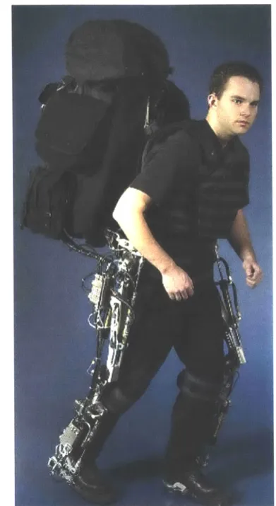
For over a century, technologists have strived to develop autonomous leg exoskeletons that reduce the metabolic energy consumed when humans walk and run, but such technologies have traditionally remained unachievable. In this thesis, I present the Augmentation Factor, a simple model that predicts the metabolic impact of lower limb exoskeletons during walking. The Augmentation Factor balances the benefits of positive exoskeletal mechanical power with the costs of mechanical power dissipation and added limb mass. These insights were used to design and develop an autonomous powered ankle exoskeleton. A lightweight electric actuator mounted on the lower-leg provides mechanical assistance to the ankle during powered plantar flexion. Use of the exoskeleton significantly reduced the metabolic cost of walking by 11 4% (p = 0.019) compared to walking without the device. In a separate study, use of the exoskeleton reduced the metabolic cost of walking with a 23 kg weighted vest by 8 i 3% (p = 0.012). A biomechanical study revealed that the powered ankle exoskeleton does not simply replace ankle function, but augments the biological ankle while assisting the knee and hip. Use of the powered ankle exoskeleton was shown to significantly reduced the mean positive power of the biological ankle by 0.033 0.006 W/kg (p<0.01), the knee by 0.042 0.015 W/kg (p = 0.02), and the hip by 0.034 0.009 W/kg (p<0.01). The Augmentation Factor was used to unify the results of the presented devices with the metabolic impacts of previous exoskeletons from literature. In the design of leg exoskeletons, this thesis underscores the importance of minimizing exoskeletal power dissipation and added limb mass, while providing substantial positive power to a walking human. These design requirements were used to develop the first autonomous exoskeleton to reduce the metabolic cost of walking.
Thesis Supervisor: Hugh M. Herr Title: Associate Professor
Acknowledgments
First, I must thank Professor Hugh Herr for the opportunity and resources to accom-plish this work. The freedom you gave me to pursue side projects and crazy ideas contributed both to my learning and enjoyment in this field. I also appreciate the guidance and support of my thesis committee - Professor Amos Winter and Professor David Trumper. Your insightful questions and recommendations provided valuable new perspectives.
I sincerely thank the National Science Foundation for funding my graduate work through the Graduate Research Fellowship award no. 1122374.
To the many past and present members of the Biomechatronics Group, includ-ing Elliott Rouse, Oliver Kannape, Jean-Frangois Duval, Grant Elliott, Sarah Hunter, Ernesto Carlos Martinez-Villalpando, Michael Eilenberg, David Hill, Jared Markowitz, David Sengeh, Madeleine Abromowitz, Lindsey Reynolds, Bruce Deffenbaugh, and Ken Pasch: I could not have asked for a better group of people to work with (and sometimes not-work with).
A special thanks goes to Tim Burns, Sarah Bjorkman, and Allan Lubben. Your support and passion encouraged me to pursue my interests regardless of immediate justification. Who would have guessed that catapults are actually relevant to robotic
prostheses?
Finally, I cannot give enough thanks to my parents, grandparents, Jake, Ally, Stephanie, Wingnut, and the rest of my family. You let me take over the garage and workshop. You taught me that a loose tape measure hook is a design feature not flaw. You served as some of my earliest and most dedicated subjects. Most importantly, one of you always knows when I need a good face-licking. I am truly fortunate to have all of your love and support.
Contents
1 Thesis Summary 1.1 Specific aims. . . . . 1.2 Hypotheses . . . . 1.3 Thesis contributions . . . . 2 Introduction 2.1 Background . . . . 2.1.1 Exoskeleton definition . . . . 2.1.2 Power conventions . . . . 2.1.3 Exoskeleton applications . . . . . 2.1.3.1 Metabolic reduction . . 2.1.3.2 Strength augmentation . 2.1.3.3 Energy generation . . . 2.1.4 Exoskeleton classification . . . . . 2.1.4.1 Passive exoskeletons . . 2.1.4.2 Active exoskeletons . . . 2.2 Exoskeleton challenges . . . . 2.2.1 Device mass and inertia . . . . . 2.2.2 Device size and volume . . . . 2.2.3 Efficiency and energy density . . 2.2.4 Force application . . . . 2.2.5 Controls . . . . 15 15 15 16 17 . . . . 1 7 . . . . 1 7 . . . . 1 7 . . . . 1 8 . . . . 1 8 . . . . 1 9 . . . . 2 1 . . . . 2 1 . . . . 2 1 . . . . 2 4 . . . . 2 5 . . . . 2 5 . . . . 2 6 . . . . 2 6 . . . . 2 6 . . . . 2 72.2.7 Joint motion complexity . . . . 2.2.8 Human adaptation ... ...
3 Augmentation Factor (AF)
3.1 A F m otivation . . . . 3.2 A F calculation . . . . 3.3 AF calculation examples . . . . 3.3.1 Positive mean net power . . . . 3.3.2 Negative mean net power . . . . 3.4 Initial comparison of exoskeletal AFs . . . . 3.5 Current comparison of exoskeletal AFs . . . . 3.6 Design implications of AF . . . . 4 Exoskeletal design 4.1 Design requirements 4.2 Joint selection . . . 4.3 4.4 4.5 4.6 4.7 4.8 Design decisions . . . . Exoskeleton architecture . . Electric exoskeleton actuator
Strut design . . . . Electronics . . . . Control . .. .. . . .. . . 4.8.1 Initialization state
4.8.2 Swing state . . . . . 4.8.3 Early stance state . .
4.8.4 Powered plantar flexic
~n
state5 Augmented walking during load carriage 5.1 Exoskeleton v1 design . . . . 27 27 29 29 29 34 34 36 38 40 43 47 . . . . 4 7 . . . . 4 9 51 53 56 64 69 72 72 74 75 75 77 77 . . . .
5.4 Actuator testing results . . . . 5.5 Loaded walking results . . . . 5.6 Loaded walking discussion . . . .
6 Augmented unloaded walking
6.1 Exoskeleton v2 design . . . .
6.2 Experimental procedures . . . . 6.2.1 Exoskeletal torque measurement . . 6.2.2 Walking protocol . . . . 6.2.3 Data analysis and processing . . . . 6.2.4 Statistical analysis . . . . 6.3 Biomechanical results . . . . 6.3.1 Torque measurement calibration . . 6.3.2 Metabolic cost and joint mechanics 6.4 Biomechanical results of individuals . . . .
6.4.1 Subject 1 . . . . 6.4.2 Subject 2 . . . . 6.4.3 Subject 3 . . . . 6.4.4 Subject 4 . . . . 6.4.5 Subject 5 . . . . 6.4.6 Subject 6 . . . . 6.5 Discussion of biomechanics . . . . 6.5.1 Biological plus exoskeletal system . 6.5.2 Ankle joint augmentation . . . . . 6.5.3 Implications on exoskeletal design . 6.5.4 AF implications . . . . 6.5.5 Future design improvements . . . .
7 Future work and conclusion
84 84 86 89 . . . . 89 . . . . 92 . . . . 9 2 . . . . 96 . . . . 96 . . . . 98 . . . . 9 9 . . . . 9 9 . . . . 99 . . . . 108 . . . . 108 . . . . 113 . . . . 117 . . . . 121 . . . . 125 . . . . 129 . . . . 133 . . . . 133 . . . . 134 . . . . 135 . . . . 136 . . . . 136 137
List of Figures
2-1 BLEEX Exoskeleton . . . . 20
2-2 Yagn exoskeleton . . . . 23
3-1 Pdis definition . . . . 31
3-2 Effects of added limb mass . . . . 33
3-3 AF calculation example (net positive power) . . . . 35
3-4 AF calculation example (net negative power) . . . . 37
3-5 Initial AF comparison (2013) . . . . 39
3-6 Current AF comparison (2015) . . . . 41
3-7 Individual AF results . . . . 42
4-1 Functional requirements . . . . 49
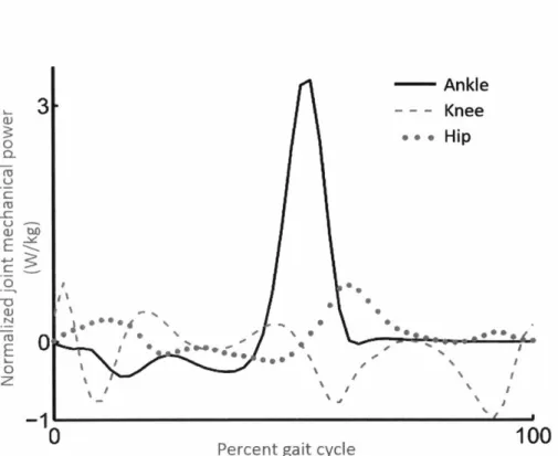
4-2 Ankle, Knee and Hip Power . . . . 50
4-3 Design decisions . . . . 53
4-4 Exoskeleton architecture . . . . 54
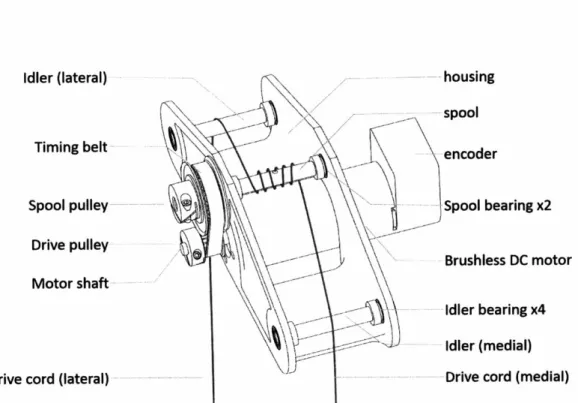
4-5 Winch actuator . . . . 57
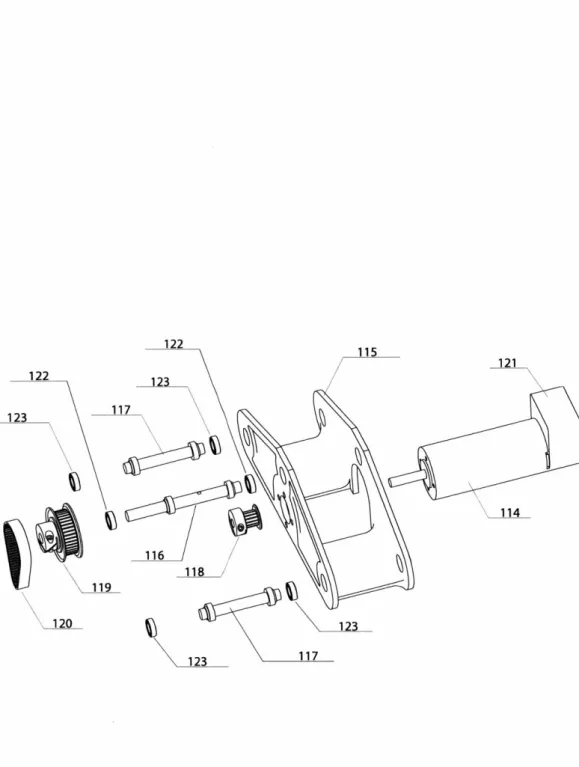
4-6 Exploded winch actuator . . . . 58
4-7 Plastic cord guard . . . . 60
4-8 Heat sink . . . . 61
4-9 Heat sink drawing . . . . 62
4-10 Strut design . . . . 65
4-11 Strut FEA . . . . 68
5-1 5-2 5-3 6-1 6-2 6-3 Exoskeleton vi . . . . Experimental protocol during load carriage . . . . Exoskeleton mechanical power and metabolic impact
Active autonomous exoske Strut markers . . . .
Experimental protocol du 6-4 Exoskeletal torque calibra 6-5 Intersubject mean powers 6-6 Joint angle profiles . . . 6-7 Ankle moment and power 6-8 Knee and hip moment an 6-9 Subject 1 ankle profiles
6-10 Subject 1 knee profiles 6-11 Subject 1 hip profiles 6-12 Subject 2 ankle profiles 6-13 Subject 2 knee profiles
6-14 Subject 2 hip profiles
6-15 Subject 3 ankle profiles 6-16 Subject 3 knee profiles 6-17 Subject 3 hip profiles 6-18 Subject 4 ankle profiles 6-19 Subject 4 knee profiles 6-20 Subject 4 hip profiles 6-21 Subject 5 ankle profiles 6-22 Subject 5 knee profiles 6-23 Subject 5 hip profiles .
6-24 Subject 6 ankle profiles 6-25 Subject 6 knee profiles
. . . . 80
. . . . 83
. . . . 85 leton v2 . . . . 90
. . . . 9 3
ring unloaded walking . . . . 96 tion results . . . 100 . . . . 1 0 1 . . . . 1 0 3 profiles . . . . 105 i power profiles . . . . 106 . . . . 1 0 9 . . . . 1 1 0 . . . . I I I . . . . 1 1 4 . . . . 1 1 5 . . . . 1 1 6 . . . . 1 1 8 . . . . 1 1 9 . . . . 1 2 0 . . . . 1 2 2 . . . . 1 2 3 . . . . 1 2 4 . . . . 1 2 6 . . . . 1 2 7 . . . . 1 2 8 . . . . 1 3 0 . . . . 1 3 1
List of Tables
3.1 Initial Augmentation Factor calculations . . . . . 3.2 Current Augmentation Factor calculations . . . . 5.1 5.2 6.1 6.2 6.3 6.4 6.5 6.6 6.7
Exoskeleton v1 component mass distribution . . . Individual metabolic and mechanical power . . . .
Intersubject biomechanical scalar results Biomechanical scalar results for subject 1 Biomechanical scalar results for subject 2 Biomechanical scalar results for subject 3 Biomechanical scalar results for subject 4 Biomechanical scalar results for subject 5 Biomechanical scalar results for subject 6
(90 kg) (80 kg) (82 kg) (98 kg) (99 kg) (84 kg) 38 43 79 86 . . . . 107 . . . . 112 . . . . 113 . . . . 117 . . . . 121 . . . . 125 . . . . 129
Chapter 1
Thesis Summary
1.1
Specific aims
* Develop a simple exoskeletal model to predict the metabolic impact of walking with an exoskeleton.
" Design and develop a lightweight and high-powered ankle exoskeleton.
" Measure the metabolic impact of wearing the ankle exoskeleton while walking.
" Measure the metabolic impact of wearing the ankle exoskeleton while walking during load carriage.
* Measure the biomechanical impact at the ankle, knee and hip while wearing a powered ankle exoskeleton.
1.2
Hypotheses
"
An ankle exoskeleton capable of providing substantial levels of positive me-chanical power with minimal added distal mass will reduce the metabolic costof walking.
provided by the body.
1.3
Thesis contributions
"
The Augmentation Factor was presented as a general framework of exoskeletal performance to assist exoskeleton designers in predicting the metabolic impact of a device design. The AF uses the device's mass, location of mass, and applied power to predict the metabolic effect [I]." A powered ankle exoskeleton was developed to efficiently provide biological lev-els of torque and power to the user. Distal mass was minimized through the use of fiberglass struts and a winch actuator mounted on the shin [1, 2j.
" A biomimetic controller was developed for the exoskeleton to assist the user during early stance and powered plantar flexion, but provide no assistance or resistance during the swing phase of walking
11,
21." Use of the powered ankle exoskeleton was shown to reduce the metabolic cost of normal walking by 11 4% (p = 0.019) in a study with six participants
walking at 1.4 m/s
12,
31." Use of the powered ankle exoskeleton was shown to reduce the metabolic cost of walking with a 23 kg vest by 8 t 3% (p = 0.025) in a study with seven participants walking at 1.5 m/s [1].
" Use of the powered ankle exoskeleton was shown to significantly reduce the mean positive power of the biological ankle by 0.033 0.006 W/kg (p<0.01),
the knee by 0.042 0.015 W/kg (p = 0.02), and the hip by 0.034 0.009 W/kg (p<0.01) [3].
" Use of the active exoskeleton reduced the mean positive power of the biolog-ical muscle-tendon system, but the mean positive power of the total system
Chapter 2
Introduction
2.1
Background
2.1.1
Exoskeleton definition
In this thesis, exoskeletons are defined as:
mechanical devices that are essentially anthropomorphic in nature, are 'worn' by an operator and fit closely to the body, and work in concert with the operator's movements. In general, the term 'exoskeleton' is used to describe a device that augments the performance of an able-bodied wearer, whereas the term 'orthosis' is typically used to describe a device that is used to assist a person with a limb pathology. -Herr 2009
141
2.1.2
Power conventions
Similar to muscle-tendon units, exoskeletons can provide both positive and negative power to the user. Muscle-tendon units apply positive power when the applied torque is in the same direction of the joint rotational velocity, and apply negative power when the applied torque is in the opposite direction of the joint rotational velocity. An exoskeleton applies positive power to the user when the exoskeletal torque is in the
the exoskeletal torque is in the opposite direction of the joint rotational velocity. For example, suppose an exoskeleton is designed as a simple rotational damper in parallel with a biological joint. This exoskeleton would only be capable of applying negative power to the user, since the exoskeletal torque would always resist the motion. If instead the exoskeleton was designed as a simple torsional spring, the exoskeleton would be capable of providing both positive and negative power. The exoskeleton would be applying negative power when energy was being stored in the spring and
positive power when energy was being released from the spring.
2.1.3
Exoskeleton applications
2.1.3.1 Metabolic reduction
Reducing the metabolic cost of legged locomotion is considered one of the most im-portant roles of a lower-extremity exoskeleton [5, 41. Even if reducing metabolic cost is not the primary goal, designers of exoskeletal technologies must be able to offset the detrimental impact of device mass and inertia. Users may be willing to sacrifice modest increases in energy expenditure for devices that offer increased protection or capabilities, but even maintaining metabolic cost requirements close to normal physi-ological levels is often a difficult technphysi-ological challenge; additional mass added to the body results in increased biological joint work and metabolic rate. During level walk-ing, Browning et al. [61 showed that the metabolic increase associated with adding mass to the foot is more than four times greater than the same mass attached to the waist. Lower-extremity exoskeletons counteract the effects of device mass through assistive exoskeletal forces and moments applied to the body. The energy needed for locomotion is shared between the walking human and the worn exoskeleton with the goal of maintaining or even lowering the human energetic contribution as compared to normal physiological levels required when the device is not worn.
demonstrated to reduce the metabolic demand for either walking, loaded walking or running.
2.1.3.2 Strength augmentation
The ability to carry substantial loads is required by many professions, including those that may experience cognitive deficits associated with the extreme physical demands. For example, soldiers are often expected to carry loads between 20-35 kg at speeds of 1.5-1.75 m/s for over 10 km in a single march [8]. Wheeled vehicles, however, are excellent at reducing the effort of carrying substantial loads, but terrain and space restrictions often limit the practicality of a vehicle and require the versatility of legged locomotion. Exoskeletons have the potential to reduce the energetic cost of carrying such loads while maintaining the flexibility of legged locomotion. Interest in devel-oping exoskeletons to augment strength and endurance has increased substantially, driven by the accelerating pace of innovation in several mechanical and computer-related disciplines [9, 10, 111.
Researchers have attempted to reduce the metabolic burden of load carriage by developing both passive and active exoskeletons. Walsh et al. presented a device that used springs in parallel with the ankle and hip joints along with a variable damper at the knee [121. A preliminary study showed that the device transferred 80% of a 36 kg payload to the ground, but a 10% metabolic increase was observed while wearing the exoskeleton. Kazerooni & Steger developed a powerful lower extremity exoskeleton for load carriage with actuated hip, knee and ankle joints (Figure 2-1) [9]. The device allowed a user to walk at 1.3 m/s while carrying a 34 kg payload along with the 36 kg exoskeleton, but a metabolic improvement was not shown. Both of these devices distributed the payload weight through the structure of the exoskeletons, thus reducing the weight borne by the human user. The device presented by Walsh et al. achieved this by providing high knee damping during the early stance phase of walking, while Kazerooni & Steger's device provided active power at the joints to support the load. However, the added mass of these sophisticated exoskeletons may
Figure 2-1: This iinage of the Berkeley Lower Extreiity Exoskeleton (BLEEX) is taken from Kazerooi &7 Steger 2006
191.
The BLEEX exoskeleton was designed to aid iinilitary personnel and emtergency first, responders with load carriage.2.1.3.3 Energy generation
Exoskeletons can also be used to harvest energy from the user in order to power other electrical devices. The exoskeleton serves as an energy transformer that converts the user's muscle work into useful electrical energy. Donelan et al. developed a device that uses an electromagnetic generator to harvest energy from the knee in a biomimetic fashion [13, 141. Harvesting energy during periods of negative power at the knee was less metabolically detrimental than continuous harvesting, but a metabolic increase of over 20% was still observed. The inefficiency of muscle converting metabolic en-ergy into mechanical work is a difficult hurdle for enen-ergy harvesting exoskeletons to overcome. The efficiency of muscles and the implications of this study will be more thoroughly discussed in Chapter 3.
2.1.4
Exoskeleton classification
Exoskeletons can be classified into two categories: passive and active. Passive ex-oskeletons are often lightweight, but due to their lack of power supply and electron-ics, their controllability is limited
115,
161. Active exoskeletons generally implement electronic control systems that can modulate exoskeletal behaviors for different condi-tions [17, 181, including the adjustment of positive power to the user [19, 20, 1, 2, 211. Furthermore, exoskeletons can be classified as either tethered or autonomous. Teth-ered exoskeletons require a connection (e.g. pressurized lines, electrical wires) to an external mass not worn on the body, typically an energy source or control hardware [19, 181. Unlike tethered exoskeletons, the entire system of an autonomous exoskele-ton is worn by the user [15, 22, 1, 231, and thus, auexoskele-tonomous exoskeleexoskele-tons are typically not limited to a laboratory setting.2.1.4.1 Passive exoskeletons
One of the first leg exoskeletons that posited to augment human legged locomotion was a passive exoskeleton patented in the late 19th century by Nicholas Yagn [241.
an "apparatus for facilitating walking, running and jumping." To my knowledge, this device was never manufactured or tested. A drawing from the patent is shown in
Figure 2-2.
Passive exoskeletons have been shown to reduce the metabolic cost of cyclic mo-tions using lightweight designs that store and release substantial amounts of strain energy. In the study of Grabowski & Herr 1151, a lightweight, passive exoskeleton was shown to significantly reduce the metabolic cost of hopping by an average of 24%. The hopping exoskeleton used leg-parallel fiberglass leaf springs between the user's feet and hips to store and release energy. During each hop, approximately half of the required eccentric and concentric leg work was provided by the exoskeleton's leg springs, likely reducing the metabolic cost by reducing the mechanical muscle-tendon work. The large elastic recoil and low device mass both contributed to the success of the hopping exoskeleton. The knee joint in human hopping can be approximated as a torsional spring, exerting minimal torque during full knee extension with torque increasing with increasing knee flexion angle. In the study of Farris et al. 1251, a passive elastic ankle exoskeleton was shown to significantly reduce the cost of hop-ping by 13%. Wearing the elastic exoskeleton also resulted in both a reduction of soleus activation and force generation, but a reduction in positive fascicle power was not observed. The biomechanical profile of hopping enables simple and lightweight exoskeletal designs that can passively store elastic energy during knee flexion and an-kle dorsiflexion and then release that stored energy during knee extension and anan-kle plantar flexion.
Van Dijk et al. presented an exoskeleton that has a spring spanning the ankle, knee and hip joints 1261. The parameters of the parallel springs were optimized to minimize the absolute residual biological joint work during walking. The average energy expen-diture of walking increased by over 30% while wearing the device. Although passive exoskeletons have not reduced the metabolic cost of walking in healthy individuals,
N. YAGN.
APPARATUS FOR FACILITATING WALKING, RUNNING, AND JUMPING.
No. 420,179. Patented Jan. 28, 1890.
66%
Figure 2-2: This image is taken from a patent decribed by Nicholas Yagn in an 1890 US patent
1241.
This design is one of the first recorded examples of an exoskeleton. The proposed exoskeleton used springs parallel to the legs to assist walking and running.2.1.4.2 Active exoskeletons
Practical applications such as permanent assistive devices and augmentative exoskele-tons for recreation or military purposes require autonomous devices where the human wearer carries their own source of energy and control. Such active autonomous leg exoskeletons have been designed with the aim of augmenting running and walking. Elliott et al. [17, 281 developed an autonomous active exoskeleton for running using the observation that the biological knee can be approximated as a spring during the stance phase of slow to moderate-speed running. Similar to the hopping exoskeleton of Grabowski & Herr [151, the running exoskeleton also used fiberglass leaf springs on the distal and proximal sides of the knee, but the static knee joint of the hopping exoskeleton was replaced with a controllable, high-torque and lightweight clutch. The articulated knee joint allowed the leg to freely flex during the swing phase and then locked the joint during stance to enable storage and release of strain energy in the leg-parallel leaf springs. Such exoskeletons can also be described as "quasi-passive" since the electrical energy is only used to control the device and no battery energy is converted to mechanical energy applied to the user. Quasi-passive exoskeletons may only require small batteries to operate electronics and low-power actuators, such as a clutch. Upon evaluation, the device was not shown to reduce the metabolic cost of running. The authors argued
117]
that the lack of metabolic augmentation was due to the negative impact of device added mass, poor human-device mechanical energy transfer, and insufficient energy return from the parallel leg springs.In order to mitigate the effects of artificial joint alignment and device inertia, Asbeck et al. developed a soft exosuit [23, 211. Bowden cable actuators were mounted outside of a backpack near the wearer's pelvis to reduce the added distal mass of the exoskeleton. The exosuit used textiles and the actively controlled Bowden cables to apply tensile forces in parallel with the lower-extremity muscles. The Bowden cable was routed along the anterior surface of the thigh, passing laterally across the knee
moments. During level ground walking, the powered exosuit was shown to reduce the metabolic cost of walking when compared to the powered-off exosuit 1211. However, it has not been shown to reduce the metabolic cost of walking when compared to the no exosuit condition, possibly a consequence of the 10.1 kg system mass.
One effective strategy for reducing the mass of a worn active exoskeleton is to move the energy source and control hardware off the body [18, 19, 291. For example, the worn mass of pneumatic exoskeletons can be reduced by tethering the device to off-board compressed air and control valves. A tethered pneumatic ankle exoskeleton was shown to reduce the metabolic cost of level-ground walking by 6% when compared to normal walking 119]. Despite the tethered nature of this devices, the study shows that it is possible to reduce the metabolic cost of walking by assisting the ankle with a lightweight device capable of providing positive mechanical power. Tethered exoskeletons provide a means to study the effects of active exoskeletons with a high specific power, but their range is limited to within the laboratory.
2.2
Exoskeleton challenges
Many factors have hindered the development of an autonomous performance-enhancing exoskeletons. The following technological and human limitations have challenged ex-oskeleton designers.
2.2.1
Device mass and inertia
Adding mass to the lower limbs requires additional metabolic power, and the effects are amplified as the mass is moved distally (further away) from the hip
[61.
Fur-thermore, the metabolic cost associated with additional device mass increases with walking speed 1301. In an effort to reduce the weight of the worn exoskeleton, re-searchers have developed passive and quasi-passive exoskeletons. Without an active actuator, these devices are not able to provide levels of positive power that overcome the negative metabolic effects of added device mass 112, 26, 13j. Researchers haveuse lightweight textiles to actuate the ankle and hip, while the heavy actuators are located near the wearer's pelvis.
2.2.2
Device size and volume
Unlike a prosthesis, exoskeletons are not replacing mass and volume previously occu-pied by a biological limb. Prostheses can be designed to fit within the form factor of the limb which they are replacing. Exoskeletons must be designed to fit around the biological limbs. The additional device volume often restricts motion or alters the gait.
2.2.3
Efficiency and energy density
Autonomous exoskeletons that provide net positive power to the user must also carry their own energy source, typically batteries, liquid fuel, or compressed air. The spe-cific energy of batteries is still a fraction of the energy density of many foods. For example, a lithium iron phosphate battery has an energy density of about 400 J/g (A123 Systems), while chocolate has an energy density of about 23000 J/g (Hershey chocolate bar). A 100 gram chocolate bar has similar energy density as a 6 kg battery, but there is currently no portable technology that is capable of efficiently converting this food chemical energy into electricity. Exoskeletal actuators and transmissions must be as efficient as possible to reduce the required battery mass.
2.2.4
Force application
The human body has an amazing muscular-tendon system that is capable of applying kilonewtons of force to the skeleton, but it is a challenge to apply similar loads to the body's exterior. While running, an adult may produce peak torques of 200 Nm at the knee joint. If one assumes a lever arm of 5 cm, then the muscle-tendon unit is exerting 4 kN. This does not even account for the effect of agonist and antagonist
withstand external loads. Typically, exoskeletons attempt to apply forces that are normal to the skin's surface in order to minimize shear forces that are uncomfortable and inefficient.
2.2.5
Controls
Exoskeleton control systems aim to assist the user in a natural manner without unin-tentional restrictions. Typically, exoskeletons are controlled to mimic that biological joint which they are assisting (i.e. apply joint torques in the same direction as the muscle-tendon units). The slight variations in each individual's gait make it difficult to develop generic control algorithms. Furthermore, it is not definitely known that exoskeletons should apply torque in a biomimetic fashion. Exoskeletons may be able to augment their users by fundamentally altering the gait.
2.2.6
Customization
People come in all types of shapes and sizes. Exoskeletons must be either customized for a specific user or be adaptable to different physiques. Developing custom struc-tures for each subject is costly and time consuming, but generic designs may lead to discomfort and inefficient load transferring.
2.2.7
Joint motion complexity
Exoskeletons can either simplify joint motions in order to reduce the degrees of free-dom or attempt to mimic the joint and account for all degrees of freefree-dom. Simplifying the joint motion often results in a lighter, smaller and simpler device, but restricts the natural range of motion. Multiple degrees of freedom can be incorporated into the exoskeleton, but this often adds additional device mass, volume, and complexity.
2.2.8
Human adaptation
and, as a result, find the device awkward. It is often unclear if these discrepancies are a failure of exoskeleton control or a personal resistance to external forces. Current solutions often include extensive training over multiple days or even weeks.
Chapter 3
Augmentation Factor (AF)
3.1
AF motivation
A simple model to estimate the metabolic demand of an exoskeleton design would be
a valuable tool for designers, but there are many factors which may affect exoskeletal performance. Sawicki and Ferris presented the performance index as a metric of mea-suring the relationship between applied positive exoskeleton mechanical power and change in metabolic power 1311. A higher performance index suggests that the ex-oskeleton is able to more efficiently transfer mechanical power into metabolic power. The efficient transformation of mechanical power into metabolic power is important for autonomous systems that must carry their own energy supply. The generality of the performance index enables the comparison of various exoskeletal designs, but it is limited to developed and experimentally tested devices. The performance index can-not make a prediction about the metabolic performance of an untested exoskeleton.
3.2
AF calculation
As a resolution to this difficulty, we developed a general model called the Augmen-tation Factor (AF) to predict the metabolic impact caused by a worn exoskeleton at moderate walking speeds. Commonly, devices attempt to improve metabolic rate
muscle-tendon power, providing negative mechanical power to joints during phases of negative muscle-tendon power, or a combination thereof [32, 19, 12, 131. The AF defined as
p+ pdis 4
AF = - Z imi (3.1)
estimates the change in metabolic power caused by a worn exoskeleton. The AF predicts the metabolic improvement of a device in Watts. The AF balances those mechanical exoskeletal properties that cause a metabolic improvement with those properties that cause a metabolic detriment; the AF balances the mean positive mechanical power (p+) supplied by an exoskeleton with the net mechanical power dissipation (Pdis) and added device mass on each limb segment (mi). The muscle-tendon efficiency, r, converts the mechanical power provided by the exoskeleton into metabolic power. The device masses on each limb segment (mi) are weighted by the device location factors (0i) that convert the device mass at a specific body location to a predicted metabolic power increase. The mean positive mechanical power (p+) and net mechanical power dissipation (pdis) are calculated from the profile of exoskeleton power applied over a gait cycle. Dividing the positive work provided by the exoskele-ton (integral of positive power) by the total gait cycle time results in p+. If the net work provided by the exoskeleton is positive then Pdis is equal to zero. If the net work provided by the exoskeleton is negative then Pds, is the net work divided by the gait cycle time. It is important to note that exoskeleton power profiles typically display the unilateral power. If a bilateral exoskeleton is being used (an assumption of the AF) and a unilateral power profile is provided then p+ and Pdis must be multiplied by 2. Examples of AF calculation are provided in Section 3.3.
When computing the AF for a device, a positive AF suggests that use of an ex-oskeleton will result in a metabolic improvement whereas a negative AF indicates that an exoskeleton would increase walking metabolism. The AF increases with p+
Mean positive power = Mean negative power
p, >0
pdS = 0
0 CL
Mean positive power < Mean negative power p- >0
p= mean negative power - mean positive power
Mean positive power> Mean negative power
p' >0
Pai 0
0
Time
Figure 3-1: Various power profiles are shown with the corresponding positive and dissipative powers. Note that when mean positive power is greater than the mnean negative power, the dissipative termn is zero.
energy from the body than it supplies, denoted by a negative net-power dissipation
(pdiS). The musculoskeletal complex utilizes elastic elements to efficiently store and release energy during level ground walking [33, 34, 51. Negative net-power removed by an exoskeleton, Pdis, cannot be stored elastically and reused by the body, resulting in additional positive muscle-tendon work and an increased metabolic rate. A graph-ical representation showing the relationship between p+ and Pdis is shown in Figure 3-1. The muscle-tendon efficiency, 7, is used in equation 3.1 to convert exoskeletal mechanical power to metabolic power. This value was obtained by taking the mean of efficiency values empirically determined in previously published exoskeleton stud-ies, j = 0.41 mechanical Watts for every metabolic Watt [19, 351. As such, 41 W of positive mechanical power supplied by an exoskeleton replaces 100 W of metabolic power. The empirically obtained efficiency is consistent with previous studies inves-tigating the positive muscle fascicle work efficiency of 0.4 during walking [36, 371.
Studies on isolated rat and frog muscle performing positive work showed efficiencies of 0.2-0.25 [38, 391. The muscle efficiency of 0.2-0.25 represents a lower efficiency limit for joint positive power since energy stored elastically in tendons and ligaments and released during concentric muscle-tendon contractions have a positive impact on such an efficiency [35, 311.
Finally, the AF also accounts for the metabolic burden due to additional leg mass by the sum of the products of the device location factors (13i) and the exoskeletal component masses (mi). The included exoskeletal masses are those worn on the foot, shank, thigh and waist (enumerated by i in equation 3.1). The device location factors
(0i) are 14.8, 5.6, 5.6, and 3.3 W/kg from ankle to waist, respectively [6]. Browning et
al. provided linear regression equations for each segment that relate added mass to net metabolic rate normalized by body mass. The device location factors were obtained by taking the product of the linear regression slopes and the average subject mass studied by Browning et al. The figure from Browning et al. showing these relationship is shown in Figure 3-2.
4.5
4.0
*
Foot
.
I
._IThIgh
-
o
3.5
woo-imo
.- '10 Waist
25 dim'
2.01
0
4
8
12
16
Load (kg)
Figure 3-2: This image is taken from Browning et al.
161.
The metabolic cost as-sociated with adding various masses at the foot, shank, thigh and waist are shown. Browning et al. report the following linear regression equations: Waist W/kg - 2.360.045m, Thigh W/kg 2.38 1 0.075m, Shank W/kg 2.34 t 0.076m, Foot WV/kg 2.36 + 0.20m. The metabolic results are normalized by the subjects' masses (hence the W/kg), and m represents the mass of the additional mass. The y-intercept repre-sents the normalized metabolic cost of walking without any additional masses. The imean subject mass was reported to be 74.16 kg.
3.3
AF calculation examples
The following subsections outline the calculation of the AF for two different examples. The first example shows an exoskeleton that provides positive mean net power over the gait cycle, resulting in Pdis being equal to 0. The second example shows an exoskeleton that provides negative mean net power over the gait cycle, resulting in Pdis being equal to the mean net power.
3.3.1
Positive mean net power
Figure 3-3 shows an example power profile for an exoskeleton that provides net pos-itive power. The exoskeleton is bilateral and applies the same power profile to both the left lower limbs and the right lower limbs. The power profile is described by
P = -t sin(-), where P is the mechanical power provided by the exoskeleton to the
user and t is the percent gait cycle ranging from 0 to 100. The middle and bottom plots show only the positive and negative power, respectively. The exoskeleton pro-vides a mean net power of 15.9 W, a mean positive power, p+, of 23.8 W and a mean negative power of -7.9. Since the mean net power is greater than zero, Pdis is equal
to 0. The exoskeleton has a total mass of 4 kg: 0.2 kg on each foot, and 3.6 kg on the waist.
Following equation 3.1, the AF is calculated as follows:
AF = 2 * 23.8W + 0
-
S
(3.2)
Y
3m, = 2 * 0.2kg * 14.8 + 3.6kg * 3.3- (3.3)1kg kg
AF 98.3W (3.4)
100 r 50 0
z
-50 0 20 40 60 80 100 100 -50 0 a-> 0 c/) 0 0 0 20 40 60 80 100 100 50 -0 0~ 0) a)z-
5 0 ' ' 0 20 40 60 80 100Percent Gait Cycle
Figure 3-3: An example power profile for an exoskeleton that provides net positive power is provided. The unilateral power profile is described by P -1 sin( 1,) wer
P is the mechanical power provided by the exoskeleton to the user and I is the percent
gait cycle ranging from 0 to 100. The middle and bottom plots show only the positive and negative power, respectively. The exoskeleton provides a mean net power of 15.9 W, a mean positive power, p+, of 23.8 W and a mean negative power of -7.9. Since the mean iiet, power is greater than zero, pm, is equal to 0.
3.3.2
Negative mean net power
Figure 3-4 shows an example power profile for an exoskeleton that provides net neg-ative power. The exoskeleton is bilateral and applies the same power profile to both the left lower limbs and the right lower limbs. The power profile is described by
P = t sin(), where P is the mechanical power provided by the exoskeleton to the user and t is the percent gait cycle ranging from 0 to 100. The middle and bottom plots show only the positive and negative power, respectively. The exoskeleton pro-vides a mean net power of -15.9 W, a mean positive power, p+, of 7.9 W and a mean negative power of -23.8. Since the mean net power is less than zero, Pdis is equal to the mean net power, -15.9 W. The exoskeleton has a total mass of 4 kg: 1 kg on each shank, and 1 kg on each thigh.
Following equation 3.1, the AF is calculated as follows:
AF = 2 * 7.9W- 42 * 15.9W -
>
3m, (3.5)Z2
* kg 5.6 + 2 *1kg * 5.6 (3.6)k g kg
AF -61.4W (3.7)
The p+ and Pdis terms are multiplied by 2 since the exoskeleton applies the same power profile to both sides of the body. The negative value of the AF predicts that the exoskeleton will increase the metabolic cost of walking by 61.4 W.
50 F 0 0 . 50
z
-100 0 20 40 60 80 100 50 -0 0 > -50 0 50 -0L -100 ' 0 20 40 60 80 100 ,50-0 -0' 0 20 40 60 80 100Percent Gait Cycle
FigurLe 3-4: An exampIle power profile for an exoskeleton that providles
net
negative lpower* is provided. The power profile is described by P =1. sin( 2T1), where P is the mechanical power provided by the exoskeleton to the user and t is the percent gait cycle ranging from 0 to 100. The middle and bottom plots show only the positive and negative power, respectively. The exoskeleton provides a meannet,
power of' -15.9 WN,a
mean positive power, p+, of 7.9 V and a mean negative pOwer of -23.8. Since the meannet
power is less than zero, pa, is equal to the mean net power, -15.9 NV.3.4
Initial comparison of exoskeletal AFs
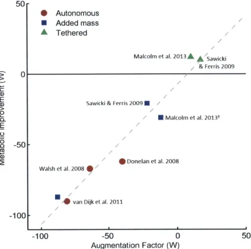
To elucidate the mechanisms that underlie the metabolic performance of leg exoskele-tons in walking, the AF was calculated for previously published exoskeleexoskele-tons that re-ported metabolic and mechanical power information (Figure 3-5 and Table 3.1). The included previous studies span a large range of device designs and metabolic impacts
135,
19, 12, 13, 261. Powers that were not explicitly stated in literature were computedfrom provided graphs. The included exoskeletal masses are those worn on the foot, shank, thigh and waist (enumerated by i in equation 3.1). The
3
coefficient was 14.8W/kg for mass added to the foot, 5.62 W/kg for the shank, 5.55 W/kg for the thigh,
and 3.33 W/kg for the waist
161.
Researchers have used springs, damping elements, and actuators in various arrangements, with all previously published autonomous exoskeletons increasing metabolic energy consumption, and only non-autonomous, tethered exoskeletons decreasing metabolic demand. Using linear regression, the AF was able to explain the metabolic results of all exoskeletons with an R2 equal to 0.95.4
Study Mass p+ pdis mfo mha0n. mthiq amist /3imi AF Metabolic impact Units (kg) (W) (W) (kg) (kg) (kg) (kg) (W) (W) (W)
van Dijk et al. 2011 75 3 0 3* 3* 3* 3* 88 -81 -90
75 0 0 3* 3* 3* 3* 88 -88 -87
Walsh et al. 2008 76 7 -5 1.41 1.41 5.12 3.66 69 -64 -67
Donelan et al. 2008 78 0 -9 0 1.6 1.6 0 18 -40 -62
Malcolm Ct al. 2013 66 9 0 0.4** .** 0 0 12 10 12 - -
-66 0 0 0.4** 1.1** 0 0 12 -12 -31
Sawicki & Ferris 2009 80 16 0 0.75 2.0 0 0 22 17 10 80 0 0 0.75 2.0 0 0 22 -22 -21
Table 3.1: Five studies were found that reported both metabolic results and applied mechanical power
113,
19, 35, 40, 26, 12J. Powers that were not explicitly stated inliterature were computed from provided graphs. The included exoskeletal masses are those worn on the foot, shank, thigh and waist (enumerated by i in equation 3.1). The
/
coefficient was 14.8 W/kg for mass added to the foot, 5.62 W/kg for the shank,5.55 W/kg for the thigh, and 3.33 W/kg for the waist
161.
Studies with a second row represent the metabolic results of wearing the exoskeleton in a powered-off state. *The location of the exoskeleton mass was not described, so the mass was evenly distributed across the leg. **The exact location of the exoskeleton mass was not described, but the device is similar to the device studied by Sawicki & Ferris, so the same mass distribution was used.
50-* Autonomous
0 Added mass A Tethered
Malcolm et al. 2013 Sawcki
& Ferris 2009
0 a)
E Sawicki & Ferris 2009 U
0 U Malcolm et al. 20136 E 0
50
* Donelan et al. 2008 Walsh et al 2008* van Dijk et al. 2011
-100
-100 -50 0 50
Augmentation Factor (W)
Figure 3-5: The AF was calculated for five devices and compared to the imeasured netabolic impact for each device
113,
19, 35, 26, 121. Circle markers are previously published autonomous devices; triaigle markers are tethered devices; square iiark-ers are exoskeleton worn in a powered-off state. lie equation estimated by linear regression is y = 0.99x - 7.4 with an R2 equal to 0.95. In the AF equation, tihe p+tern is calculated by taking the positive work done by an exoskeleton during the gait cycle and dividing by the gait cycle duration. If the miean net power provided by the exoskeleton is negative, then p'is is equal to this negative mean net power, otherwise, p ds is zero.
3.5
Current comparison of exoskeletal AFs
Figures 3-6 and 3-7 and Table 3.2 include the previous exoskeleton devices from lit-erature and also the AFs of the studies presented in this thesis 11, 31. An additional exoskeleton study that was published in 2015
1161
is also presented. Figure 3-7 de-picts the individual metabolic results and AF calculations for the experimental trials discussed in Chapter 6 and [3]. The individual results show a wide range of metabolic effects due to only the additional mass. During the powered-off exoskeleton condition, all of the subjects wore the exoskeleton, with the same mass at each body location; thus, the AF is identical for all six subjects. Browning et al. [61 and Sawicki & Ferris [311 showed similar variations when their subjects wore similar masses. Interestingly, Sawicki & Ferris showed that that the metabolic cost of carrying the exoskeletal mass decreased by nearly 8% over 3 trials separated by 3-5 days. The metabolic cost of carrying the additional mass dropped by approximately 4% after each trial. It is unknown how much longer this trend would have continued if additional trials were performed. Figure 3-7 shows that although the effects of additional mass varied greatly between subjects, all of the subjects improved their metabolic cost once the exoskeleton was powered. The adaptation seen in1311
suggests that with additional training, the results of the autonomous powered exoskeleton may have been improved.Autonomous Added mass Tethered Mooney et al. 2014 @0 Mooney & Herr 2015 Collins et al. 2015 . Malcolm et al. 2013,&
Collins et al. 2015.
A
Sawicki& Ferris 2009
Mooney & Herr 2015 U Sawicki & Ferris 2009 N
M Malcolm et al. 20136
0
Donelan et al. 2008 Walsh et al. 2008 00 van Dijk et al. 2011
-50 0
Augmentation Factor (W)
Figure 3-6: The AF' was calculated for eight devices and compared to the measured
metabolic impact for each device 113, 19, 35, 26, 12, 1, 3, 161. Circle markers are
published autonomous devices; triangle narkers are tethered devices; square
iark-ers are exoskeleton worn in a powered-off state. The equation estimated by linear regression is y = 1.1x [ 1.6 with an R2
equal to 0.93. In the AF' equation, the p4
termi is calculated by taking the positive work done by an exoskeletoti during the gait (:vcle and dividing b)y the gait cycle duration. If the net-work done by the exoskele-ton is negative, then p'li' is equal to this negative net-work divided by the gait cycle duration, otherwise, p'(I is zero.
50 r A.
0
Q' C E CU a-) 2050
--100 -100 50Autonomous Added mass Tethered
Autonomous (individual subject) Added mass (individual subject)
F
I I I I I I I
-100 -80 -60 -40 -20 0 20
Augmentation Factor (W)
40 60 80 100
Figure 3-7: The AF calculation and metabolic results for six individual subjects are shown. The subjects wore the autonomous powered exoskeleton v2 during level ground walking. The experimental procedure and results are discussed in Chapter 6 and
131.
The hollow blue squares represent wearing the exoskeleton during the powered-off condition. The hollow red circles represent wearing the exoskeleton during the active condition. The diagonal black lines connect the two data points of an individual subject. 420
03 100 80 -60 40 -20 - 6-I E 0 CL E 0 -5 -O 0 -20 --40 --60 -801--100 1,4
Study Mass p+ pdis rnoot mshank mthigh mwaist Z/imi AF Metabolic impact
Units (kg) (W) (W) (kg) (kg) (kg) (kg) (W) (W) (W)
van Dijk et al. 2011 75 3 0 3* 3* 3* 3* 88 -81 -90
75 0 0 3* 3* 3* 3* 88 -88 -87 Walsh et al. 2008 76 7 -5 1.41 1.41 5.12 3.66 69 -64 -67 Donelan et al. 2008 78 0 -9 0 1.6 1.6 0 18 -40 -62 Malcolm et al. 2013 66 9 0 0.4** 1.1** 0 0 12 10 12 - ---66 -0 -0 -0.4** -1.1** -0 0 -12 _-12 -31
Sawicki & Ferris 2009 80 16 0 0.75 2.0 0 0 22 17 10 80 0 0 0.75 2.0 0 0 22 -22 -21 Mooney et al. 2014 84 23 0 0.5 1.75 0 1.71 23 33 36 - Mooney Herr 2015 89 23 0 0.08 2.04 0 1.48 18 28 38 - ---89 -0 -0 -0.08 2.04 -0 -1.48- 18 - -18 --10 Collins et al. 2015 77 3.7 -2.5 0.37 0.54 0 0 8.5 -5.5 17 77 0 0 0.37 0.54 0 0 8.5 -8.5 0.5
Table 3.2: Eight studies were found that reported both metabolic results and applied mechanical power [13, 19, 35, 40, 26, 12, 1, 3, 161. Powers that were not explicitly stated in literature were computed from provided graphs. The included exoskeletal masses are those worn on the foot, shank, thigh and waist (enumerated by i in equation 3.1). The
3
coefficient was 14.8 W/kg for mass added to the foot, 5.62 W/kg for the shank, 5.55 W/kg for the thigh, and 3.33 W/kg for the waist [6]. Studies with asecond row represent the metabolic results of wearing the exoskeleton in a powered-off state. *The location of the exoskeleton mass was not described, so the mass was evenly distributed across the leg. **The exact location of the exoskeleton mass was not described, but the device is similar to the device studied by Sawicki & Ferris, so the same mass distribution was used.
3.6
Design implications of AF
The AF suggests the importance of an exoskeleton to provide substantial positive mechanical power to the wearer with minimal added leg mass and net-negative power dissipation. That is, using the fundamental characteristics of device mechanical power and mass, the potential metabolic impact can be estimated using the AF. The metabolic results observed in this study were achieved by a device with an AF of 33 W. Previously, the most successful published exoskeleton (Malcom et al.) had an AF of 10 W. That device was tethered, having an external power supply and yet showed one third the metabolic improvement (12 W) of the device I present in this thesis (36 W) [191. Historically, previously published autonomous exoskeletons have not provided a metabolic improvement, demonstrated by their negative AF values (Figure 3-6). In accordance with the AF, to design a non-dissipating exoskeleton
4
tive power, p+ > q
Z/imi
(Equation 3.1). Furthermore, a purely dissipative device(p+ = 0 and pdis < 0) will have a negative AF (e.g. (Donelan et al. 2008)) and an
estimated increase in metabolic cost. Future investigators can use the AF to estimate the metabolic impact of an exoskeletal leg design, reducing the likelihood of the device unintentionally increasing walking metabolic energy once fabricated.
Certain assumptions are made when calculating the AF. The AF does not account for different control schemes and only accounts for mechanical power and added distal mass. That is, the AF assumes that power is added in a biomimetic fashion where positive and negative power are added by the exoskeleton during phases of the gait cycle when the joint is also applying positive or negative power, respectively. Current and previous exoskeletal control methodologies apply power in this way. The muscle-tendon efficiency of 0.41 used by the AF is also an estimate based on two studies [19, 35]. The muscle-tendon efficiency may also be specific for each joint and activity [41]. In this work, comparisons are made between exoskeletons that were tested with load carriage and those that were tested during unloaded conditions. The effect of added load on the metabolic improvement of an exoskeleton is unknown, but may be an advantage compared to unloaded studies. Because of the limited number of studies documenting the metabolic impact of exoskeletal walking, the calculation of the AF in this study assumed that the muscle-tendon efficiency was not affected by different loading conditions. More studies are needed to precisely determine how this apparent muscle-tendon efficiency is affected by joint and activity. Furthermore, the transfer of mechanical energy between joints is not fully considered when calculating
the AF.
Literature suggests that energy is transferred between joints via bi-articular muscle-tendon action when one joint is performing negative power and another is exhibiting positive power
133,
341. This may explain why the device presented by Donelan et al. increased the metabolic rate higher than predicted by the AF [13J; a knee exoskeleton that harvests electrical energy from negative phases of knee mechanical work mayThe possible metabolic advantage of an exoskeleton reducing the negative mechanical power applied by muscle-tendon units is also not considered by the AF. Providing a joint with negative power during phases of eccentric muscle work may reduce the metabolic burden. However, muscles are substantially more efficient at eccentric work than they are at concentric work [51, thus, aiding the joints during eccentric phases is less effective at reducing the metabolic expenditure during walking, when compared to aiding concentric contraction phases.
The equation found by linear regression of the AF and measured metabolic effect, y = 1.1x + 1.6, (95% C.I. slope: [0.90, 1.291, intercept: 1-6.60, 9.831), highlights some important features of the AF. When no device is worn the AF should predict no metabolic change; that is, a device that does not supply power and has no mass should have no metabolic effect. The nearly zero y-intercept correctly accounts for this case. The slope of the linear regression is approximately one, indicating the ability of the AF to predict metabolic change caused by a worn exoskeleton. The AF includes the aforementioned assumptions as well as the empirically-estimated muscle-tendon efficiency for positive mechanical work (rq). Future work will focus on the validation of these assumptions.
Chapter 4
Exoskeletal design
The primary goal of this thesis was to develop an autonomous exoskeleton capable of reducing the metabolic cost of walking. This chapter discusses the design re-quirements, design choices and general exoskeleton architecture. Two versions of the exoskeleton have been developed. The specifications for the exoskeleton v1 design are discussed in Chapter 5. This initial exoskeleton was used during load carriage experiments. The specifications for the exoskeleton v2 design are discussed in Chap-ter 6. The exoskeleton v2 was used during the unloaded walking trials, including the biomechanics study. The two designs are architecturally similar with the major difference being the strut length and corresponding transmission ratio.
4.1
Design requirements
The framework provided by the Augmentation Factor along with the desire for an autonomous and safe device provided a set of requirements summarized in Figure 4-1 and outlined below:
e The AF of the exoskeleton must be greater than zero. In order to achieve a positive AF, the exoskeleton must provide substantial positive power while min-imizing distal mass and net power dissipation. Ideally, the net power provided