HAL Id: hal-02447929
https://hal.archives-ouvertes.fr/hal-02447929
Submitted on 26 Nov 2020
HAL is a multi-disciplinary open access
archive for the deposit and dissemination of sci-entific research documents, whether they are pub-lished or not. The documents may come from teaching and research institutions in France or abroad, or from public or private research centers.
L’archive ouverte pluridisciplinaire HAL, est destinée au dépôt et à la diffusion de documents scientifiques de niveau recherche, publiés ou non, émanant des établissements d’enseignement et de recherche français ou étrangers, des laboratoires publics ou privés.
High efficiency ISOL system to produce neutron
deficient short-lived alkali RIBs on GANIL/SPIRAL 1
facility
V. Kuchi, P. Jardin, C. Michel, L. Maunoury, M. Dubois, P. Delahaye, O.
Bajeat, S. Hormigos, V. Métayer, M. Maccormick, et al.
To cite this version:
V. Kuchi, P. Jardin, C. Michel, L. Maunoury, M. Dubois, et al.. High efficiency ISOL system to produce neutron deficient short-lived alkali RIBs on GANIL/SPIRAL 1 facility. 18th International Conference on Electromagnetic Isotope Separators and Related Topics, Sep 2018, Geneva, Switzerland. pp.163-168, �10.1016/j.nimb.2019.05.070�. �hal-02447929�
High efficiency ISOL system to produce neutron deficient short-lived alkali RIBs on
GANIL/SPIRAL 1 facility
V. Kuchi
1, P. Jardin
1, C. Michel
1, L. Maunoury
1, M. Dubois
1 P. Delahaye1, O. Bajeat1, S. Hormigos1, V. Métayer1, M. MacCormick2, B. Roussière2, J. Guillot21
GANIL (Grand Accélérateur National d’Ions Lourds), 14076 CEAN cedex5, France
2
Institut de Physique Nucléaire (IPN), 91406 Orsay, France
E-mail : [email protected]; [email protected];
ABSTRACT
The SPIRAL1 (Système de Production d’Ions Radioactifs Accélérés en Ligne) facility at GANIL (Grand Accélérateur National d’Ions Lourds) is developing new techniques to access nuclei in the neutron-deficient isotope region far from the stability-valley, with Z ranging from 30 to 60. The availability of different primary beams, ranging from carbon to uranium with energies up to 95 MeV/A, gives an opportunity to produce a large variety of radioactive ion beams. The production of neutron-deficient short-lived alkalis by fusion-evaporation reactions is the focus of this work. A simple and compact target ion source system is designed to produce isotopes of 74Rb ( = 64.8 ms) and 114Cs ( =
570 ms). The efficiencies of the different processes involved in the production are evaluated. Radioactive recoils are produced by the interaction of heavy-ion beams, respectively 20Ne@1013 pps and 58Ni@1012 pps, with a thin 58Ni target. High atom-to-ion transformation (ATI) efficiency should be obtained above 70% and 90% for 74Rb and 114Cs nuclei respectively. The expected intensities of the RIBs are estimated to be about 104 pps at the exit of the TISS.
Keywords: neutron-deficient isotopes, fusion-evaporation reaction, ISOL technique, surface
ionization, Target Ion Source System, SPIRAL1 Upgrade.
Introduction
The upgraded SPIRAL1 facility [i,ii,iii] aims to extend the production of new radioactive ion beams at GANIL using the Isotope Separator On-Line (ISOL) method [iv]. It provides the opportunity to produce RIBs using a large variety of stable beams, from carbon to uranium, at energies ranging from 4 to 95 MeV/A on different target masses up to Niobium, and with different types of nuclear reactions, such as fragmentation, transfer and fusion-evaporation.
To extend the choice of RIBs available at the SPIRAL1 facility, a technique using fusion-evaporation reaction has been chosen as it favours neutron deficient isotope regions. This region is hardly accessible at other ISOL facilities, where mainly spallation, fragmentation, and fission techniques are used [v,vi]. The fusion reaction requires a low energy primary ion beam which defines the target thickness. The fusion-evaporation channels used here have relatively large cross-sections, of the order of 100 mb and the residual survival probability is optimised by using materials where the thin-target approximation remains valid. In another hand, low energy limits the power deposited in the target, which allows the design of a compact TISS, as the dimensions are closely related to the target
size and thus to the primary beam power. In case of short-lived isotopes, the compactness of the TISS is of first importance to limit the release time of the nuclei out of the production system and thus the losses due to their radioactive decay. The objective of the following TISS design was to estimate how efficient could be the TISS performance if it is optimized to favour the atom-to-ion transformation efficiency rather than the number of nuclei produced in the target.
As done within the SPIRAL1 framework, the TISS had also to be as simple as possible to cope with the constraint of operational reliability. The final design and the main related studies are presented in the following paragraphs.
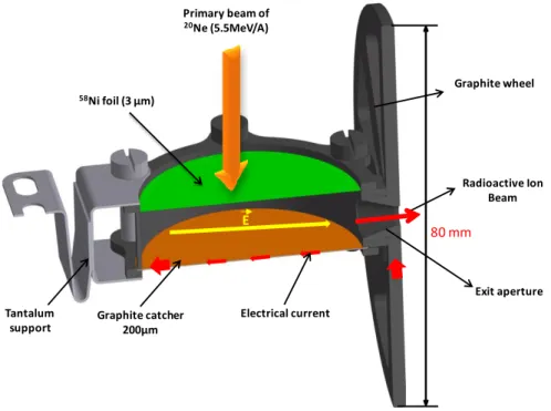
The general principle is outlined in Figure 1. Ions from primary fusion-evaporation processes in a thin self-supporting target are neutralized and thermalized in a "catcher" matrix and undergo temperature-driven diffusion back up to the catcher's surface and into the TISS vacuum cavity. The atoms are accumulated in the cavity and are ionized by the surface-ionization process. An electric field, parallel to the foils, pushes the ions towards an exit hole, beyond which they are strongly accelerated to form a radioactive ion beam. Then they are mass-separated and magnetically selected for experiments.
As ions must be 1)-surface-ionised, 2)-short-lived, 3)-neutron-deficient and 4)-interesting for the SPIRAL1 users, 74Rb ( = 65 ms) and 114Cs ( = 570 ms) isotopes have been chosen. They both
can be produced with primary beams of 20Ne and 58Ni respectively sent on a 58Ni target.
This approach was first implemented by R. Kirchner and colleagues in the 70’s and 80’s [vii,viii] with a TISS exploiting fusion-evaporation reactions in a thin production target, and associated with either a FEBIAD ion source or a reduced volume thermal-ion source. In the original design, energetic nuclei produced in the target passed through a window were stopped in a solid catcher, diffused and effused up to an ionizing zone, then guided on out of the source. The cavity was maintained at a high temperature (up to ) to speed up the release of radioactive atoms from the catcher and to reduce sticking time on the TISS walls. Despite the very small cavity volume (of the order of 1 cm ), the atom-to-ion transformation (AIT) time for Kr and Xe was of the order of 1 ms. "Sticking" (effusion) or diffusion times were not considered initially and, had they been so, one would have predicted longer extraction times for chemically reactive elements and low AIT efficiencies for metallic elements with half-lives shorter than 1 ms. In more recent years, gaseous catchers have been designed and improved [ix] to get rid of the sticking time issue but require voluminous vacuum systems, unsuited to SPIRAL1 infrastructure.
Figure 1: Principle of the TISS. Radioactive ion production follows steps 1 to 6.
Description of the TISS design
The TISS (see Figure 2) mainly consists of two radial foils of 50 mm in diameter intersected by a 12 mm graphite cylinder (0.8 mm thick, 12 mm height and 50 mm in outer diameter). The ring is made of TOYO TANSO graphite (IG-19 type) [x]. The first foil directly impinged by the primary ion beam acts as a target (58Ni) and the second one acts as a catcher for the recoil products and low energy primary beam. The first foil is the production target and is 3 µm or 6.5 µm thick for the production of 74Rb or 114Cs respectively. The second foil is made of a flexible graphite “paper”, commercially called Papyex®, its microstructure is strongly anisotropic, leading to anisotropic properties between parallel planes and perpendicularly to the plane of the foil. Ni and Papyex® foils are pressed on the cylinder edges with two flanges assembled by screws. This system is the cavity. A current is injected in the walls of the cavity, i.e. walls of the ring and of the foils, through a flexible tantalum band situated at the opposite side from the exit aperture of the TISS. The current leaves the cavity through a graphite wheel connected to the cavity at the exit aperture. Both extremities of tantalum band and graphite wheel are fastened to cooled parts, on the current feedthrough and vacuum chamber respectively. Owing to the current flowing through the resistive materials of the graphite ring, graphite foil and Ni foil, the cavity is heated (nominally at 1600 K) and an electric field oriented towards the exit aperture is created within the cavity. According to the supplies in the production cave of SPIRAL 1, where this TISS will be installed in fine, 300 A of current is potentially available to heat the cavity walls.
74
Rb ions will be studied using a primary beam of neon 20Ne (intensity of 1.8.1013 pps at an energy of 5.5 MeV/A) impinging on the target. In the case of 114Cs, the primary beam will be 58Ni (intensity of 3.1012 pps at an energy 4 MeV/A). The produced isotopes and the primary beam are stopped in the graphite catcher 12 mm beyond the target. The isotopes diffuse and effuse out of the catcher, are ionized by contact with the hot surfaces of the cavity due to their relatively high work function (5 eV
Primary beam of heavy ions at ~5.1 MeV/A
Production target
(foil of several µm thick) • Thick enough to
maximize the in-target production
• Thin enough to let the reaction products go through Implantation Thickness (~10µm) Stopper material ~1700 K Production of radioactive isotopes by fusion-evaporation reactions Recoil Reaction product Diffusion of implanted radioactive atom HV I Accelerated ion beam Surface ionization (for alkalis) Exit aperture of the TISS High current for
ohmic heating and E field creation
Electric field
Ions pushed toward the exit aperture
for graphite and 4.7 eV for the nickel). Then they are pushed towards the exit hole by an electric field, which reduces the effusion time before their exit from the cavity. The creation of an electric field directly depends on the material resistivity and on the current injected in the TISS. A relevant choice of materials is thus particularly important to simultaneously cope with the constraints of high temperature (melting point, thermal expansion), transport of the electric and beam power (thermal conductivity and emissivity), ionization ability (work function higher than the first ionization potential if possible), sticking time, porosity and electrical resistivity.
Figure 2: Cross-section view of the TISS for the production of 74Rb isotopes
The nickel target, the Papyex® catcher and the graphite cavity are connected in parallel. In an electrical point of view, their thicknesses have been chosen to avoid short-circuit between two of these three resistors by the third one. As if done so, it would lead to concentrate the electrical heating power on only one resistor, and thus on only one part of the cavity. Owing to the number of parameters involved in the final result and to their interdependency, the final values have been obtained after several iterations using a thermo-electrical simulation described in the following paragraph.
The nickel foil and graphite container must have a low open porosity to limit the probability for isotopes to escape. The catcher must present high open porosity to favour the release of isotopes once they are implanted. Recent characterisation of Papyex® porosity [xi] obtained using helium pycnometry technique (Micromeritics-ACCUPYC 1330) [xii] shows that the Papyex® material consists of approximately 49% pores and 51% material. Among the pores, 90% are open and 10% are closed, revealing Papyex® as a good catcher candidate.
Simulations
The three-dimensional finite element model (FEM) shown in Figure 4 has been developed using the ANSYS code. The main purpose of simulations was to study the thermal configuration, the thermo-mechanical constraints and the electrical potential of the different parts of the TISS cavity. The
Radioactive Ion Beam 80 mm Graphite catcher 200µm Electrical current Exit aperture Primary beam of 20Ne (5.5MeV/A) 58Ni foil (3 µm) E Graphite wheel Tantalum support
simulations were accomplished assuming a 20Ne @ 5.5 MeV/A primary beam power of 308 W, including 38 W lost in the 3 µm nickel target and 270 W deposited in the catcher. A current of 300 A was considered to heat the TISS cavity. In the simulations, electrical resistivity of 1 m.cm [xiii] and 60 µ.cm [xiv], thermal conductivity of 55 W.m-1.K-1 and 80 W.m-1.K-1, and emissivity of 0.45 and 0.2 were taken for Papyex® and Nickel respectively.
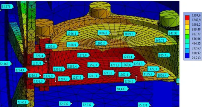
Figure 3: Thermal simulations of the temperature (°C) over the cavity, taking into account the power deposited by the 20Ne primary beam in the Ni target (38 W), in the catcher (270 W) and the electrical power of 1350 W.
The results show that the maximum temperature is 1611 K, near to the exit aperture of the cavity. At this temperature, the lifespan of the graphite part is higher than the one required for the on-line operation (2 weeks). This statement is based on the SPIRAL1 experience. The present SPIRAL1 targets irradiated by 1.5 kW of the 40Ar primary beam and heated at more than 2100 K for two weeks do not present any visible damage. The maximum temperature on the nickel target is lower than 1667 K. This is under the nickel melting point temperature (1728 K), but too closes if we consider an uncertainty of 100 K on the temperature calculation, which is regularly observed during the comparison between experimental and simulated values of temperature. A progressive increase of the ohmic heating while measuring the Ni temperature was thus respected to avoid damaging the Ni foil.
As demonstrated in a previous work [xv], an electric field close to 1 V/cm applied in an ionizing tube of C or Re 4 mm in diameter and 3 cm long can significantly improve the ionization efficiency of alkali atoms. This is explained by a reduction of the probability the atoms have to stick to the tube once ionized. One goal of the present cavity design was to obtain an inner electric field of the same order of magnitude, and eventually slightly lower as the dimensions of the cavity are larger than those of the tube. Obtaining an electric field higher than 1 V/cm in such a large cavity with a maximum current close to 300 A is technically difficult but seemed to be possible. A too important electric field is not desirable as it can limit the distance of the ion jumps and increase the time spend by the ions on the surface.
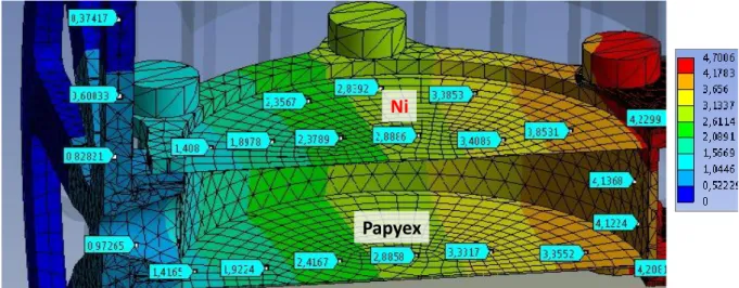
Figure 4: Electric potential along the TISS cavity at a current of 300 A obtained with ANSYS code. The electric potential within the TISS cavity has been estimated using the electric potential solver in ANSYS Fluent. In Figure 4, the electric potential gradient is similar along the Papyex® foil, the nickel foil and the graphite ring, which was a condition to efficiently lead the ions towards the exit aperture. The potential difference between the extremities of the TISS cavity is close to 4 V for a current of 300 A. Thus the electric field is close to 0.8 V/cm, as desired.
Monte-Carlo simulations
The effect of the electric field on the effusion time of the ions was calculated with a Monte-Carlo simulation based on the SIMION code [xvi]. A specific routine has been written and introduced in the code. A molecular regime of effusion is assumed. At each collision, the particle sticks to the wall surface (adsorption following the Frankel’s equation [xvii]) and then is re-emitted (desorption) into the TISS volume following the cosine Knudsen law distribution [xviii]. The calculation for one ion is stopped when the particle leaves the TISS cavity. For each event, the number of collisions with the surface and the time of flight (TOF) are saved. The mean velocity considered corresponds to the Maxwell-Boltzmann velocity distribution. The effusion time was deduced from the TOF, the sticking time and the mean number of collisions. The results of the simulation for 74Rb and 114Cs are presented in Figure 5.
Ni
Figure 5: Effect of electric field on effusion time. The red and orange lines represent effusion time with and without an electric field for 74Rb. The green and purple lines indicate the effusion time with and without an electric field for 114Cs. The sticking times per contact took in the calculations were equal to 0.5 ms and 1 ms for 74Rb and 114Cs respectively.
To evaluate the effect of the electric field on the effusion time, the simulations were done with and without an electric field for 74Rb and 114Cs. Radioactive decay was not taken into account. Calculated effusion times include the sticking time of rubidium on the graphite, which is equal to 0.5 ms [xix], and which is mainly responsible for the effusion time. The electric field changes the effusion time from ∼100 ms (for 50% of the population) to 12 ms. If the radioactive decay of 74Rb ( =65 ms) is
taken into account, the effusion efficiency without and with electric field goes from 39% to 84%. For cesium, the total effusion time goes from 190 ms down to 27 ms, leading respectively to effusion efficiencies of 75% and 95% if one takes into account the half-life of 114Cs (0.57 s). For all these calculations, Rb and Cs have been considered as permanently ionized in the cavity.
Total TISS efficiency
Once produced, radioactive isotopes undergo three processes in the formation of ion: diffusion out the target material, effusion and ionization. If one assumes that these processes are sequential, the total efficiency of atom-to-ion transformation is given by:
The release efficiencies of 74Rb and of 114Cs out of the catcher are respectively equal to 90% and 97%, according to their diffusion coefficient of 2.10-8 and 2.5.10-8 m2.sec-1 extracted from [xx]. These high efficiencies are also due to the low recoil energy and thus low implantation depth of the 74Rb and 114
Cs recoils in the catcher material (<12 µm). The effusion efficiencies deduced from the simulations 0 100 200 300 400 500 600 700 0 500 1000 1500 2000 2500 N um ber o f pa rti cl es Time (ms)
74Rb with an electric field 74Rb without an electric field 114Cs with an electric field 114Cs without an electric field
are equal to 84% and 96%. According to Langmuir equation [xxi], the ionization probabilities per contact for Rb and Cs atoms on graphite surface are equal to ~98% and ~100% respectively at 1600 K. Thus the AIT efficiencies of 74Rb and of 114Cs are estimated to be respectively equal to 74% and 93%. Expected production rates are given in Table 1.
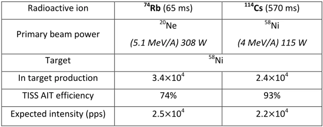
Table 1: Expected 74Rb and 114Cs intensities versus production parameters. The in‐target production rates are estimated using cross-sections issued from the PACE (Projected Angular‐momentum Coupled Evaporation) fusion-evaporation code [xxii].
Radioactive ion 74Rb (65 ms) 114Cs (570 ms)
Primary beam power
20 Ne (5.1 MeV/A) 308 W 58 Ni (4 MeV/A) 115 W Target 58Ni In target production 3.4 104 2.4 104
TISS AIT efficiency 74% 93%
Expected intensity (pps) 2.5 104 2.2 104
Ongoing tests
The TISS has been installed on the SPIRAL1 test bench at GANIL. The first step is to characterize the thermo-mechanical behaviour of the TISS at an operational temperature of 1600 K. It is installed in a water-cooled vacuum chamber and is heated by the circulation of current passing through the walls of the cavity, foils and graphite ring. Temperatures of the target and catcher were measured using an optical disappearing filament pyrometer [xxiii]. There were two main sources of uncertainty in the temperature measurement: one is related to the operator, adjusting the colour of the filament on the source of light; it is estimated to 1%. One is related to the knowledge of the emissivity of the material considered. In the case of Papyex®, a slight modification of the roughness obtained with a grade 400 (average particles size is 400µm) abrasive paper can make the emissivity vary from 0.44 to 0.46 [xxiv]. In the case of Ni, the emissivity has been taken equal to 0.2. The overall uncertainty is then estimated at 5.3 %. The temperatures of the target and of the catcher are presented in Figure 6 versus the power applied on the cavity. Due to the measurement method, one could observe the Papyex® temperature only through an aperture of 5 mm in diameter performed in the centre of the Ni target (see Figure 7).
Figure 6: Temperature of the target (Nickel, purple squares) and catcher (Papyex®, red circles) versus total power delivered by the power supply. Maximum TISS power is 1560 W.
The temperature of the catcher is higher than the one of Ni, which can be explained by the resistance of the catcher which is lower than the Ni ones. As shown in Figure 7, the temperature of the Ni target is uniform in its central region (~1430 K) and is higher on its periphery (more than 1580 K). This can again be explained by the lower resistance of the graphite ring, leading it to higher heating and temperature.
The potential difference between the extremities of the TISS cavity is equal to 6.5 V, which includes the potential difference on the graphite wheel (0.7 V) and on the tantalum support (1 V). The potential difference present on the TISS cavity is thus equal to 4.8 V, which leads to an electric field of 4.8 V/50 mm close to the targeted value of 1 V/cm.
Figure 7: View of the Ni window and of the Papyex® foil through the hole performed in the centre of the Ni foil. The peripheral region of the Ni foil is hotter than the central region.
0 200 400 600 800 1000 1200 1400 0 500 1000 1500 2000
Te
mp
er
atu
re
(
°C)
Power (W)Temperature on Catcher (PAPYEX) Temperature on Nickel 47 mm Graphite catcher 1583 K Ni target 1450 K Hot spot > 1583 K Outer diameter of Ni target
After two days of continuous operation, the nickel target ruptured, first in the hot spot region indicated in Figure 7 and finally all along the perimeter. The region surrounding the exit aperture was identified as the hottest region during the thermal simulation. Despite the risk, the test was performed as the confidence in the absolute determination of the temperature with ANSYS could be subject to an uncertainty of several tens of degrees. This observation will now be taken into account to make the temperature delivered by the code match with the experimental temperature. The design of the cavity will be improved to limit the risk of melting of the Ni foil and to get a more homogeneous temperature throughout the cavity.
Once the window disappeared, the TISS was maintained continuously under operation at a current of 230 A during three weeks without technical problems or observable modification of the voltage/current couple. As expected, this confirms that the graphite parts are reliable for 2 weeks period, as required for online operation. A second test will be performed by 2019 with an upgraded version of the TISS.
References
i P. Jardin et al. Nucl. Inst. Methods Phys. Res. B 376 (2016), 64-67. ii L. Maunoury et al., JINST 13 C12022 (2018).
iii P. Delahaye et al., these proceedings. iv H.L. Ravn, Phys. Rep. 54 (1979), 203.
v X. Campi and J. Hüfner Phys. Rev. C 24 (1981), 2199. vi Yu.Ts.Oganessian et al., Nucl. Phys. A 701 (2002), 87-95. vii R. Kirchner et al. Nucl. Inst. and Methods 186 (1981) 295-305
viii R. Kirchner and E. Roeckl, Nucl. Instrum. and Methods 133 (1976) 187-204 ix I.D. Moore, P. Dendooven, J. Arje, Hyperfine Interact (2014) 223:17-62 x Toyo tanso: http://www.toyotansofrance.com/
xi Measurements performed by J. Guillot, IPN Orsay, July 2018
xii F. J. Semel and D. A. Lados, “Porosity analysis of PM materials by helium pycnometry,”
Powder Metall., vol. 49, no. 2, pp. 173–182, 2006.
xiii https://www.mersen.com/uploads/tx_mersen/12-PAPYEX-graphite-expanse-Mersen_04.pdf, p.8
xiv P. P. Corporation, “Heat Capacity and Electrical Resistivity of Nickel in the Range 1300-1700 K Measured with a Pulse Heating Technique,” vol. 4, no. 4, 1983.
xv A. Pichard et al., Rev. Sci. Instrum. 81, 02A908 (2010)
xvi D. A. Dahl, “SIMION for the personal computer in reflection,” Int. J. Mass Spectrom., vol. 200, no. 1–3, pp. 3–25, 2000.
xvii V. J. F. Leningrad, “Theorie der Adsorption und verwandter Erscheinungen .,” pp. 117–138,
1924.
xviii M. Knudsen, “The Cosine law in the kinetic theory of gases,” Ann. Phys., vol. 48, pp. 1113– 1121, 1915.
xix A. Pichard, “Développement de faisceaux d’ions radioactifs pour le projet SPIRAL 2. Physique Nucléaire Expérimentale [nucl-ex],” Univ. Caen, pp. 1–292, 2010.
xx A. Magerl, “Diffusion and melting in two dimensions: A quasielastic neutron scattering study of alkali metals in graphite,” vol. 40, no. 11, pp. 7616–7632, 1989.
xxi I. Langmuir and K. H. Kingdon, “Thermionic Effects Caused by Vapours of Alkali Metals,”
Proc. R. Soc. A Math. Phys. Eng. Sci., vol. 107, no. 741, pp. 61–79, 1925.
xxii A. Gavron, Statistical model calculations in heavy ion reactions., Phys. Rev. C - Nucl. Phys., vol. 21, 1980.
xxiii Commercial available disappearing filament optical pyrometer. xxiv V. Kuchi, PhD thesis report, Oct. 17th, 2018, page 159.