Publisher’s version / Version de l'éditeur:
Vous avez des questions? Nous pouvons vous aider. Pour communiquer directement avec un auteur, consultez la première page de la revue dans laquelle son article a été publié afin de trouver ses coordonnées. Si vous n’arrivez pas à les repérer, communiquez avec nous à [email protected].
Questions? Contact the NRC Publications Archive team at
[email protected]. If you wish to email the authors directly, please see the first page of the publication for their contact information.
https://publications-cnrc.canada.ca/fra/droits
L’accès à ce site Web et l’utilisation de son contenu sont assujettis aux conditions présentées dans le site LISEZ CES CONDITIONS ATTENTIVEMENT AVANT D’UTILISER CE SITE WEB.
Internal Report (National Research Council of Canada. Division of Building Research), 1979-11-01
READ THESE TERMS AND CONDITIONS CAREFULLY BEFORE USING THIS WEBSITE.
https://nrc-publications.canada.ca/eng/copyright
NRC Publications Archive Record / Notice des Archives des publications du CNRC :
https://nrc-publications.canada.ca/eng/view/object/?id=59108bc0-c09b-42e4-bd21-b6247d10b712 https://publications-cnrc.canada.ca/fra/voir/objet/?id=59108bc0-c09b-42e4-bd21-b6247d10b712
NRC Publications Archive
Archives des publications du CNRC
For the publisher’s version, please access the DOI link below./ Pour consulter la version de l’éditeur, utilisez le lien DOI ci-dessous.
https://doi.org/10.4224/20337896
Access and use of this website and the material on it are subject to the Terms and Conditions set forth at
Penetration of fire separations by plastic pipe: third progress report
PENETRATION OF FIRE SEPARATIONS BY PLASTIC PIPE (THIRD PROGRESS REPORT)
P.C. Attwood
ANALYZED PREFACE
The SPI-NRC fire research fellowship is a joint undertaking of the Society of the Plastics Industry of Canada and the National Research Council of Canada designed to determine whether plastic pipe can be safely used in high-rise buildings. The fellowship is administered by a steering committee that meets at intervals of approximately six months. This progress report covers the period August 1978 to March 1979 and is the third in the series, following reports IR 449 and IR 452.
Ottawa
November 1979
C
.
B. Crawford Director, DBR/NRCNATIONAL RESEARCH COLlNClL OF CANADA DIVISION OF BUILDING RESEARCH
DBR INTERNAL REPORT NO. 4 5 6
PENETRATION OF FIRE SEPARATIONS BY PLASTIC PIPE (THIRD PROGRESS REPORT)
by P.C. Attwood
Checked by: G
.
W. S.
Approved by: L.
W.
G.
Date: November 1979Prepared for: Limited Distribution
This is the third progress report on a program designed to determine whether plastic pipe can safely be used in high-rise buildings. Under study is the behaviour of plastic pipe exposed
to positive pressure fire conditions and how it can be altered by various construction assemblies. Two previous reports have addressed horizontal and vertical penetrations of fire
separations. This, the third, continues the study in these areas.
Because vented assemblies represent the most difficult application
of plastic pipe in high-rise buildings virtually all experimentation in
this program has dealt with vented systems using drain, waste and vent (DWV) pipe. Its distinctive feature lies in the fact that all tests were conducted at a positive pressure of 0.2 in. of water. Work by Tamura (1) has shown that pressure differentials of this magnitude can exist in high-rise structures during the winter months.
All the work completed in the program has been carried out using
small-scale fire resistant furnaces. Tables I and I1 provide a summary
of test assemblies and results, and Appendices A and B contain complete descriptions of the tests. Horizontal and vertical tests were treated
individually, and there were none of sequential penetrations. TEST ASSEMBLIES AND RESULTS
Drain, waste, and vent (DWV) pipes of either polyvinyl chloride
(PVC) or a c r y l o n i t r i l e - b u t a d i e n e - s t y r e n e (ABS) were used to represent simple vented plumbing assemblies. All tests were conducted on small- scale furnaces in which temperature was controlled according to the time-temperature curve stipulated in ASTM standard E-119 or ULC
standard S-101; a positive pressure of 5 mm (0.2 in.) of water was
maintained. The horizontal tests were carried out on a double-chamber
furnace described in detail in the first progress report (2). The
vertical tests required the single-chamber furnace already described in
the second progress report (3).
Horizontal Tests
Table I presents a summary of test assembly construction features, duration time of each test, and reference to appropriate figures.
It was said in the first progress report that a sleeved penetration at a 45 deg angle downward would not jeopardize the integrity of the separation for at least 1 h if 13-in. PVC pipe was used. The series of six tests now reported studied that type of construction further. Four tests studied downward 45 deg penetrations by vented plumbing assemblies of 13-in. PVC and ABS; one test, a similar arrangement using 3-in. PVC; and another test the upward 45 deg penetration by a non-vented 1;-in. PVC assembly.
Wall construction in this series varied from the simple design used
previously - two sheets of 5/8-in. type X gypsum wallboard backed by a
sheet of 16-ga sheet steel - to a standard wall section consisting of
two sheets of 5/8-in. type X GWB nailed to each side of 2- by 4-in. studs.
The 45 deg lateral represented a connection from a fixture to a vented stack. In five tests the exposed side represented the fixture end and the unexposed side a chase or shaft for the vented stack. In the sixth test the exposed side represented a stack in a chase and the unexposed side represented a P-trapped fixture and was accordingly unvented
.
The definition of failure used in the horizontal tests was any condition that allowed flame to propagate from the furnace to the
unexposed side of the wall, or any that allowed hot gases to escape from the closed system created by the furnace and the plumbing assembly.
The essential results of the tests are summarized as follows: 1. Lateral penetration of a fire separation by a 45 deg sleeved PVC
vented assembly can provide 2-h protection. The intumescent nature of PVC creates an ash plug that blocks the flow of hot gases from the fire compartment.
2. A similar construction with ABS will not create a seal.
3. An upward 45 deg sleeved penetration by a non-vented 13-in. PVC assembly can also provide 2-h protection.
4. A downward 45 deg penetration, referred to in item 1 above, appears to be limited to 3-in. pipe or smaller. Although no tests were conducted on 4-in pipe, the test on 3-in. pipe suggests that this is the maximum diameter that will form an ash plug.
Vertical Tests
The furnace used for testing vertical plumbing assemblies was
described fully in the second progress report (3). The top of the
furnace is formed by a 4-in. thick reinforced concrete slab through which the pipe assembly passes, representing vertical plumbing penetrating a fire separation. The exposed end of the pipe is capped and the unexposed end open, representing a vented plumbing assembly.
Table I1 presents a summary of test assembly construction features plus the duration time of each test and figure references. The vertical tests are subdivided in three general categories: 1) miscellaneous tests, 2) chase tests, and 3) slide valve tests.
Two tests were run in the first category, miscellaneous tests. The first used a double flapper device identical to that used in Test 0-5
reported in the second progress report (3). This test used 4-in. ABS
pipe and was designed to determine whether a mechanical barrier will function properly with vertical ABS pipe. The second test was designed to study the possibility of preventing fire spread by packing the pipe in a cooling medium at the penetration. In this test 3-in. ABS pipe was used with granulated natural gypsum as the cooling medium.
The second category, chase tests, involved a series of seven tests in which the plumbing was enclosed in a chase. A chase was constructed above the concrete floor; the 3-in. stack passed through it with a 13-in. lateral attached at a height of 21 in. Four chases were vented and three were sealed. All except two tests utilized a false ceiling, 14 in. below the concrete slab. The stack penetrated the false ceiling at 45 deg and was sleeved at both penetrations.
The third category, slide valve tests, studied the effectiveness of a single guillotine device. Seven tests were run with both 3- and 4-in. pipe sizes to determine the force required to activate such a device. A short 4-in. long steel sleeve was used with 3-in. pipe; no sleeve was used with 4-in. pipe.
The essential results of the tests are summarized below.
1. The double flapper device failed to operate properly because of pipe warpage. Manual intervention resulted in demonstration of 2-h
durability. A small design modification would overcome the deficiency experienced in this test.
2. The test utilizing granulated natural gypsum failed after 32 min. The pipe burned from the inside outwards and eventually allowed gypsum to leak into the furnace, thus removing all protection.
3. The three non-vented chase tests all lasted 2 h, with minimal damage to the chase. Of the four vented chases, three eventually burned through at the bottom of the gypsum wallboard. All four vented chases suffered considerably more damage than the three non-vented chases.
4. The creation of a non-vented chase essentially changes the positive pressure test to the equivalent of a neutral pressure test because the chase becomes pressurized as soon as the pipe perforates or the penetration becomes exposed. Collapse of the pipe at higher
temperatures prevents it from acting as a vent to the chase. 5. The manner in which the pipe collapsed in the chase at higher
temperatures was irregular.
6 . The slide valve assembly successfully pinched off both ABS and PVC
pipe and prevented fire spread when sufficient force was provided to drive the slide valve. If insufficient force was provided for ABS, the pipe became too soft to support its own weight and consequently collapsed on top of the valve assembly, preventing the slide from closing. Eventually this collapsed mass ignited. Insufficient force for PVC allowed the residual ash to hold the valve open. Sufficient force was 2155 g (4.75 lb) for 3-in. pipe and 3422 g (7.5 lb) for 4-in. pipe.
CONCLUSIONS
1. A double flapper device such as that described in test B-9 can successfully provide 2-h protection. The tested device requires a design modification to prevent interference by pipe expansion. 2. The nature of the enclosure above a horizontal fire separation can
significantly affect the behaviour of plastic pipe penetrating that separation. A sealed enclosure suffers substantially less damage than a vented enclosure.
3. A horizontal slide valve device provides a means of sealing off a penetration for both ABS and PVC pipe.
4. PVC pipe will create its own seal in a vented system if it
penetrates a vertical fire separation downwards at a 45 deg angle and if the pipe is sleeved. The length of the sleeve affects the durability of the assembly. This is valid for pipe sizes up to and including 3 in.
5. A sleeved 13-in. PVC lateral penetrating a wall upwards at a 45 deg angle will not propagate fire or allow hot gases to pass for at least 2 h if the upper end of the assembly is not vented.
REFERENCES
1. Tamura, G.T., Computer Analysis of Smoke Movement in Tall Buildings. ASHRAE Transactions, Vol. 75, Part 11, 1969, p. 81-93.
2. Attwood, P.C., Study of Penetration of Walls by Plastic DWV Pipe,
Progress Report. National Research Council of Canada, Division of Building Research, Internal Report 449, 1978.
3. Attwood, P.C., Penetration of Fire Separations by Plastic Pipe, Second Progress Report. National Research Council of Canada, Division of Building Research, Internal Report 452, 1979.
TABLE I
-
PENETRATION OF VERTICAL FIRE SEPARATIONS (45-DEG ANGLE BETWEEN WALL AND LATERAL)Pipe Size Test
No. and Material, in.
Pipe Assembly Construction
Test
Duration, Remarks min
-
A-39 14 PVC 45-deg lateral penetrates wall downward, with 5-in. long 18-ga steel sleeve at penetration; wye on stack butts against sleeve on unexposed side; wall
construction consists of 2 x 518 in. type X gypsum wallboard backed by 16-ga steel plate.
8 0 Failure at approximately 70 min
14 PVC
13 ABS
45-deg lateral penetrates wall upward, wlth 5-in. long 18-ga steel sleeve; wall construction
2 x 5/8 in. type X GWB + 16-ga steel sheet; cxposed side consists of wye with short capped vertical sections; unexposed side consists of 45-deg elbow, 2-in. horizontal P-trap filled with water, and 6-in. vertical.
45-deg lateral penetrates wall downward, with 10-in. long 18-ga steel sleeve through wall; wall
construction from exposed side 2 x 5/8 in. type X
GWB, 16-ga steel sheet, 2 x 4 wood stud, 1 x 518 in. type X GWB; pipe capped on exposed end; unexposed end of lateral enters wye and stack; top of cavity
covered with firebreak.
13 PVC Identical to test A-41 with following modifications: studs wrapped in asbestos paper; firebreak at top and bottom of cavity made of 4-in. asbestos sheet.
If PVC 45-deg lateral penetrates wall downward, with 13-in. 120 long 22-ga steel sleeve; wall construction 2 x 518 in.
type X GWB
+
2 x 4 in. stud + 2 x 518 in. type X GWB-
no metal sheet; gypsum firebreak installed on top and bottom of cavity; pipe capped on exposed end; unexposed end into wye and stack.3 PVC Identical to test A-43 above except as follows:
See Figure A 1
See Figure A2
sleeve
-
113 in. long, 24 ga steel stack-
4 in. PVCTABLE I1
-
PENETRATION OF HORIZONTAL FIRE SEPARATIONS Test No. Pipe Size and Material, in.Pipe Assembly Construction
Test
Duration, Remarks min
B-9 4 ABS Vertical pipe capped on exposed end; 12-in. sleeve at 120 See Figure B1 penetration with gravity-activated flapper at ends.
B-10 3 ABS Vertical pipe capped on exposed end; 5-in. diam 32 See Figure B2 concentric sleeve extends 14 in. upward from bottom of
slab; lower 4 in. of annular space fill J with packed rockwool and upper 10 in. filled with gr~,wlated natural gypsum.
3 PVC. Vertical stack running through chase, W/Tee ant1 120 If-in. lateral 21 in. above slab; chase constructed of
2 x 6 in. spruce studs at 16-in. centres with 5/8-in. type
X
GWB on both sides; top of chase consists of two sheets 5/8-in. typeX
GWB; pipe secured at top of chase.3 ABS Identical to test B-11 above slab; false floor 14 in. 120 below slab; pipe sleeved (5 in. long, 24-ga) and
passes through false ceiling at 45 deg angle creating offset; exposed end of pipe capped; false ceiling consisted of single sheet of 5/8-in. type X GWB.
B-13 3 ABS Identical to test B-12; pressure monitored in chase 120 as well as in furnace.
See Figure B3
See Figure B3
B- 14 3 ABS Identical to test B-13 except hole in top of chase 6 3
4
in. larger in diam than pipe.B-15 3 PVC Chase construction as in test B-14; no false ceiling. 118
B-16 3 PVC Non-vented chase and false ceiling construction as in 120
test B-12.
B-
17 3 PVC Chase constructed as in above, but vented by two 1003/4-in. holes in top; false ceiling consists of 2 x 5/8-type X GWB.
B-18 3 PVC Vertical pipe passing through slide valve assembly 24
mounted on top of concrete; 970 gm wt.
B-19 3 PVC Identical to test B-18, except clearance established 120
between base plate and pipe; 2155 gm wt.
B-20 3 ABS Identical to test 3-19. 120
B-21 4 ABS Identical to test B-19. no sleeve. 17
B-22 4 PVC Identical to test B-21. 2 6
8-23 4 PVC Identical to test B-21, 3422 gm wt. 120
B-24 4 ABS Identical to test B-23 120
APPENDIX A
PENETRATION OF VERTICAL FIRE SEPARATIONS:
Six tests (A-39 to A-44) were conducted to study the behaviour of pipe assemblies penetrating vertical fire separations at a 45-deg angle rather than the usual 90-deg angle. The basis for this series of six
tests was provided by a similar test in Series 2 (Test No. 1) reported
in the first progress report (1). There it was demonstrated that PVC
can create its own seal under fire conditions if the pipe penetrates the wall downwards at a 45-deg angle and if the pipe is sleeved at the
penetration.
The formation of this seal is clearly dependent on two characteristics of PVC - its intumescent nature and the formation of a carboniferous ash upon burning. Consequently, five of the six tests in the series now
reported used PVC pipe. Test No. 6 was designed to demonstrate that ABS
does not create a seal under the same circumstances.
A summary of test assembly constructions is presented in Table I. Five of the six assemblies utilized wall sections of approximately 2-h
fire separation: 2 x 4-in. studs at 16-in. centres covered on each side
by two layers of 5/8-in. type X gypsum wallboard. The height of the
section was 23 in., with firestopping top and bottom. Variations for
each test are noted in the discussion of that test. Test No. 1 (A-39)
This was very similar to Test No. 1, Series 2 (2), and was designed
to give an indication of the sleeve length likely to be required for 2-h resistance. Consequently, the wall construction, as indicated in Table I,
consisted of two sheets of 5/8-in. type X gypsum wallboard backed by a
steel plate. A 5-in. long, 18-ga steel sleeve was centred at the wall and fixed at a 45-deg angle. The pipe material was PVC, 13-in. d i m .
A
seal formed inside the sleeve within 10 min and blocked the flowof furnace gases until the 70-min mark when a leak formed in the ash plug. During the test thermal expansion of the pipe eventually caused the softened pipe to tear at the unexposed end of the sleeve. This did not occur in other tests and is attributed to the fact that the wye butted against the sleeve in this test; a better design would allow a
small clearance (>1 - in.) between the edge of the sleeve and the wye.
Test No. 2 (A-40)
The possibility of fire spreading from a vertical services area to a compartment prompted the design of this test assembly. The wall assembly is similar to that used in Test No. 1, but instead of exposing the end representing the plumbing fixture, the end representing the
stack connection was exposed to fire. Accordingly, the lateral pipe penetrated the wall at 45 deg upwards and terminated in a water-filled
P-trap arrangement (Figure Al). Aside from some slight smoke generation
at the edge of the sleeve no effects of fire were evident. Table A-I shows the final temperatures at the various thermocouple locations indicated on Figure Al. The temperature curves for these tests are essentially straight line plots. The fact that this assembly sustained very little damage on the unexposed side reflects on the advantages of non-vented systems.
Tests No. 3 to 6 (A-41 through A-44)
All four tests utilized the same basic construction: a section of a fire separation penetrated downward at 45 deg by a sleeved pipe. Test
No. 3 used 13-in. ABS pipe; Tests No. 4 and 5 used 14-in. PVC pipe; and
Test No. 6 used 3-in. PVC pipe. Details of construction for the wall
sections are outlined in Table
I.
Tests No. 3 and 4 clearly indicated the differences in behaviour of
PVC and ABS pipe. The performance of PVC was demonstrated to a degree
in Test No. 1 and confirmed in Test No. 4. The longer sleeve allowed the test to run the full 2-h period. Test No. 3, however, indicated that ABS does not create the same type of barrier; it is neither intumescent nor ash-forming. The result was that hot furnace gases caused deformation of the wye on the unexposed side of the wall within 12 min. The plumbing system was perforated within 15 min, and finally, the penetration was totally exposed at the 26-min mark.
The performance of the PVC system was radically different. There
was little damage to the plumbing system on the unexposed side of the wall save for some warpage due to thermal expansion and minimal
softening of the pipe at the unexposed end of the sleeve. From 90 min through to the end of the test smoke from the wall section cavity and crackling indicated that some burning was occurring in the cavity.
Inspection of the assembly at the end of the test showed that the PVC
pipe had been consumed to within 1 in. of the end of the sleeve, leaving an ash plug in the sleeve. The studs were charred on the surface.
Test No. 5 demonstrated the effectiveness of such an assembly in
conjunction with a standard 2-h fire wall. Test No. 5 (A-43) used
lJ-in. PVC and Test No. 6 (A-44) duplicated the assembly using 3-in. PVC
pipe. Figure A2(a) .illustrates the assembly and shows thermocouple locations. Both assemblies remained intact throughout the 2-h test period. Figures A3 and A4 graphically represent the temperature
readings for each test. The higher temperatures for the sleeve and air
space within the cavity for 3-in. PVC imply that the effectiveness of
the intumescence and ash-forming characteristics of PVC in creating a
plug is related to pipe diameter. The amount of pipe destruction
towards the unexposed end of the sleeve supports this conclusion. It is probable that 3 in. is the maximum diameter for which this mechanism would be successful.
A comparison of data in Tests No. 4 and 5 for sleeve and air space temperatures in the cavity shows that the temperatures for Test No. 4, which uses a protective sheet of steel as part of the wall assembly, are significantly higher; the sleeve and air space temperatures approach 1300 and 1200°F, respectively, in comparison with 650 and 700°F in Test No. 5.. It is believed that thermal expansion of the sheet during the test aggravated the cracking of the attached drywall, resulting in higher sheet temperatures and subsequently greater heat transfer to the cavity.
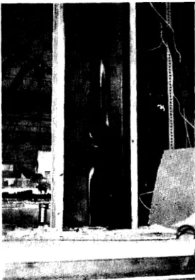
Figure A2(b) shows photographs of the assembly with 14-in. PVC, Test A-43, after 2-h exposure.
TABLE A-I
SERIES 8, TEST NO. 2 (A-40)
MAXIMUM TEMPERATURE REACHED AT THERMOCOUPLE LOCATIONS
( t = 120 min) ~ Thermocouple L o c a t i o n - -. Max Temperature 3 A t t a c h e d t o o u t s i d e o f s l e e v e 620 327 - unexposed s i d e 4 A t t a c h e d t o o u t s i d e o f elbow 2 25 107 - unexposed s i d e 5 A i r s p a c e i n s i d e p i p e - b e f o r e w a t e r s e a l 6 A i r s p a c e i n s i d e p i p e - a f t e r w a t e r s e a l
F I L L A T E R
>.nn
L 5 " L O N G 1 8 G A S T E E L S L E E V E W A L L S E C T I O N 2 x 5 1 8 " T Y P E X G W B111-
+I 6
G A S T E E L S H E E T L V E R T I C A L S E C T I O N C A P P E D A T B O T H E N D S E X P O S E DO
a
U N E X P O S E D S I D E S I D E F I G U R E A 1 T E S T A - 4 045"
( U P W A R D ) P E N E T R A T I O N O F V E R T I C A L F I R E S E P A R A T I O NT O P V l E W 2 2 G A STEEL S L E E V E , 1 3 " L O N G 2 " x 4 " S T U D 2 x 5 / 8 " T Y P E X G Y P S U M W A L L B O A R D S l D E V l E W 1:" P V C D W V PIPE 2 x 5 / 8 " TYPE X G Y P S U M W A L L B O A R D E X P O S E D + S l D E F I G U R E A 2 (a) f- U N E X P O S E D S l D E T E S T A - 4 3 - 13" P V C P E N E T R A T I O N O F F I R E W A L L A T 4 5 " A N G L E
(iii) (iv) F i g u r e A2(b) T e s t A-43 i ) Unexposed s i d e a f t e r 2 h i i ) L a t e r a l a f t e r s l e e v e removed a t end of t e s t i i i ) S i d e view o f assembly a f t e r p i p e removed, s l i g h t c h a r r i n g o f s t u d a t r i g h t
i v ) Top view o f assembly a f t e r t o p f i r e s t o p removed
v) F r o n t p a n e l removed
-
o n l y p a p e r i s scorchedI
I
I
I
I-
-
/OP
--
P
0 FURNACE TEMPERATURE - o T. C. 3 - SLEEVE-INS1 DE W A L L C A V I T Y o T.C. 8 - SLEEVE-UNEXPOSED S l DE - A I R S P A C E - I N S I D E WYE a T.C. 10 - UNEXPOSED SURFACE OF W A L L 4" A B O V E SLEEVE T.C. 4 - A I R SPACE I N S I D E WALL-
--
C A V I T Y - 5" A B O V E SLEEVE-
--
,A / A p e-
/
/ 'A-.--
#A/' 0 3 2 0 10 20 30 4 0 5 0 60 70 80 9 0 100 110 120 1 3 0 T I M E , m i n F I G U R E A 3 'TEST A - 4 3-
14" P V C P E N E T R A T I O N O F F I R E W A L L A T 4 5 " A N G L EF I G U R E A 4
1
T E S T A - 4 4 - 3" P V C P E N E T R A T I O N O F F I R E W A L L A T 4 5 " A N G L E - /--O-
/ O / o ' O 0 FURNACE TEMPERATURE-
-
P
SLEEVE - I N S I DE WALL C A V I T Y A I R SPACE I N WALL C A V I T YP
- 5" ABOVE SLEEVE SLEEVE - IJNEXPOSED S I DE-
A UNEXPOSED SURFACE OF WALL
-
o - 4" ABOVE SLEEVE A A I R SPACE I N S I D E WYE / @ / @-
-
-
-
0-
-
-
0 ' 4' d0 0 ' 0'
'
d'
/ /.'
'-.
0 " 0 /.
'
A ' A-I
I
I
I
1
APPENDIX B
PENETRATION OF HORIZONTAL FIRE SEPARATIONS:
Facilities for studying the penetration of horizontal fire
separations were described in the second progress report (3). The
sixteen tests now reported were conducted using the same furnace. The first two were miscellaneous tests designed to study means of creating a seal; the following seven studied pipe behaviour inside a chase; the last seven studied a horizontal guillotine device.
Assembly descriptions are provided in Table 11, with reference to appropriate figures. The results of these tests are discussed below. Miscellaneous Tests
Test B-9. This test was a duplication of Test B-5, except that 4-in. ABS pipe was used. A double flapper assembly is illustrated in Figure B1. The mechanism involved in the operation of this device was dependent on the thermal-viscosity properties of plastics. The bottom counterweight flapper closed within 7 min, creating an initial barrier to fire propagation. A design deficiency became readily evident when heat conduction caused the pipe above the concrete to expand. This caused the pipe to bow out in the direction of the top flapper, pushing the flapper backwards past the vertical axis and rendering it useless. Manual replacement of the flapper against the pipe allowed it to close normally after approximately 30 min of elapsed time. No change in status occurred for the remainder of the 2-h test period. Shrinkage of the plastic upon cooling caused the pipe to retract from the surface of the flapper device so that by the end of the test there was no
contact. Maximum temperature on the unexposed end of the sleeve was 482°C (900°F).
Test B-10. This test assembly (Figure B2) was designed to
determine whether a cooling substance around the outer surface of the
-
pipe would prevent flame propagation. The annular space was packed with mineral wool and granulated natural gypsum for a combined height of 14 in. Although some steam was evident, suggesting that heat was being dissipated by the gypsum, the ABS was sufficiently consumed to allow the gypsum to leak from the encasement into the furnace,
resulting in unrestrained propagation of the fire along the pipe. Chase Tests. Prior to this series all vertical tests in this program had been conducted so that the pipe above the fire separation was in an open environment. There was some concern that pipe
behaviour in the open might be different from that in a closed space where temperatures could conceivably rise if there was no ventilation. Consequently, the following seven tests were designed to determine the effect of a closed chase on the performance of pipe in a fire
The test assemblies are briefly described in Table I1 and listed as Tests B-11 through B-17. Figure B3 illustrates the basic design.
All chases were of the same basic construction: 5/8-in. type X gypsum
wallboard nailed to 2 x 6 in. spruce studs at 16-in. centres. The top of the
chase (7 ft) consisted of two layers of gypsum wallboard mounted on a 1-in. Fibrefrax pad placed on concrete. A 14-in. lateral penetrated one wall at a height of 21 in. and joined the 3-in. stack at a tee. Two basic variations of this construction were studied: ( 1 the effect of venting or sealing, and (2) the effect of a false ceiling and offset in the stack. Mica windows permitted observation of pipe behaviour in the chase.
Non-vented Chases. Assemblies in Tests B-12, 13 and 16 were identical. All penetrations of surfaces were snug, creating a chase with no venting capabilities. Pressures in the chase and in the furnace were monitored and recorded. Figure B4 (part 1) shows the pressure difference between chase and furnace; part 2 represents the actual pressure within the chase for ABS test B-13. The other non-vented chase tests showed similar pressure patterns. Pressure in the chase reached that in the furnace as soon as the main
penetration was exposed and remained at that level throughout the test, except when the main stack was perforated but unsealed. Softening of the stack at elevated temperatures created a seal and allowed pressure to equalize.
Figure B5 shows the temperature record for a thermocouple located in the air space in the lower section of the chase. The difference in the behaviour of ABS samples and the PVC sample seems to be related to material properties.
In the two ABS tests the pipe softened and stretched but never tore apart. In one test the pipe simply collapsed longitudinally and the end covered approximately 95 per cent of the penetration. In the other test the lateral separated at the tee and the stack simply stretched, so that the tee rested over the penetration. The 20 in. of pipe from the concrete to the tee had apparently been consumed. With PVC, however, the ash-forming properties prevent similar behaviour. In this case, perforation of the pipe allowed heating of the chase, and about 75 per cent of the pipe was charred. The charred sections were found zig-zagged in the chase.
Little damage to the chase was evident in the two ABS tests; in fact, the gypsum and studs were only coated with soot. In the PVC test, however, the studs were burned approximately 50 per cent at the bottom. The
photographs in Figure B6 illustrate the condition of the pipe and the chase after the tests were terminated.
Vented Chases. Test assemblies for Tests B-11, -14, -15 and -17 differed from those of non-vented chases primarily in the provision for venting.
Venting in Test B-11 occurred through small gaps between the gypsum wallboard and the studs created by thermocouple wires. When it became obvious that the venting was a factor in the outcome of the test, specific vents were provided in subsequent tests, B-14, -15 and -17.
Other variations existed and apparently affected the duration of the tests, but it is evident that the controlling variable was venting. In all cases the destruction was more severe in vented chases than in non-vented
chases. In the three PVC tests the gypsum wallboard at the base of the chase showed charring, and in Tests B-15 and B-17 it burned through the gypsum completely. Table B-I presents a summary of the extent of damage for chase tests. Figure B7 shows the temperatures recorded on the
outside of the chase, at the bottom.
Tests B-11 and B-15 had no false ceiling in the construction and Test B-17 had a double thickness of gypsum wallboard. Tests reported in
the second progress report (3) indicated that the presence of a false
ceiling improves the performance of an assembly, but the extent of
improvement is clearly variable. Visual observation of the behaviour of the section between the false ceiling and the concrete slab revealed that the manner in which the pipe behaves as temperature increases is variable from test to test. In one case the pipe separated at the elbow, allowing the elbow to sag over the end of the sleeve and form a blockage. In another, the PVC swelled and sagged but did not separate and an open path remained. The cause of variation is not clear, and consequently
repeatability is not guaranteed.
Figure B8 represents the temperatures in the air space in the lower chase region. Comparison with Figure B5 indicates the change in severity. The plot for Test B-11 is noticeably different from the plots for the other three. Examination of the chase at the conclusion of the test revealed a large mass of brittle ash collected at the bottom. A groove had been formed through the ash by hot gases, but the penetration had obviously been partially blocked for a large portion of the test. It
seems that the behaviour in Test No. 11 is transitional
-
between thatof non-vented tests and the other three vented tests. It is possible that this reflects the degree of venting, a conclusion consistent with the fact that venting in this test occurred only through gaps created by thermocouple wires.
Comparison of the results of vented chases versus non-vented chases shows that a non-vented cavity serves as a means of offsetting the
effects of positive pressure fire. Once the non-vented cavity is perforated from the fire side, it becomes pressurized to the same pressure level as the fire compartment. Under these conditions heat transfer due to mass flow of furnace gases under a pressure gradient is eliminated.
Slide Valve (Guillotine) Tests
Seven tests were conducted to demonstrate the suitability of a mechanical guillotine device in creating a seal. Tests were conducted
for both 3- and 4-in. pipe in PVC and ABS. The device for 4-in. pipe
consists of a frame to hold a sliding plate (Figure B 9 ) made of 118-in.
steel plate driven by weights suspended over the side of the furnace. Any drive force of equal strength will perform in a similar manner provided it does not interfere with the movement of the plate.
This device, like its counterpart for horizontal pipe applications, relies on temperature-viscosity properties of thermoplastics to function properly. As the plastic softens from the flow of furnace gases through the pipe, the force of the slide plate causes the pipe to pinch off. Insufficient force will allow the ash to hold the plate open, as for the PVC or, possibly, the pipe to ignite, as for ABS. The mechanism involved in the test allowed the pipe stack above the device to heat. This
temperature rise caused some warping of the stack as a result of thermal expansion. After the slide valve was closed, cooling of the pipe in turn caused shrinkage, resulting in retraction of the stack from the device. As a result there was no contact between the metal and the plastic within about 15 min of complete closure.
A force of approximately 2155 g (4.75 lb) was required for 3-in. pipe and a force of approximately 3420 g (7.5 lb) for 4-in. pipe. With these weights the slide valve closed within 39 and 25 min for 3-in. PVC and ABS pipes, respectively, and within 22 min for both 4-in. PVC and ABS pipes.
As the slide plate directly covered the penetration, it reached elevated temperatures. Figure B10 shows the temperature record for Test B-24, 4-in. ABS. Thermocouple No. 8 was located in the top of the plate directly over the penetration. Thermocouple No. 4 was 3 in. away and not over the penetration, and thermocouple No. 6 was under the
assembly. Thermocouple No. 7 was located inside the stack at the top and clearly illustrated the closing of the slide. Thermocouple locations are shown in Figure B9.
The fact that all the vertical mechanisms depended to some degree on the temperature-viscosity relation for plastic requires comment. Before enough heat can be conducted through the plastic, allowing either a simple mechanical device to close or the pipe to collapse, the stack usually provides an open path from the fire compartment to ambience. The flow of hot gases under a pressure gradient sometimes results in bursts of flame above the top of the stack as the hot gases meet the air. In no test did this result in ignition of the plastic at the top of the stack. With the slide valve, a device and fitting might be developed to trigger operation by a fusible link or some similar mechanism. This slide valve mechanism is an adaptation of devices patented by E.H. Wise and
J.J. Blumenkranz, R
E
G Sloane Manufacturing Company, Inc. (Bl).REFERENCE
TABLE B-I
DESTRUCTION IN VENTED AND NON-VENTED CHASES
Test Time of
No. Observation Observation
Vented Chases
B-11 4 0
-
audible crackling of burning woodPVC 65 - paper on exterior of gypsum wallboard at base of chase charred
120
-
PVC ash gathered at base of chase; collapsed remnant hangingfrom top
B-14 6 0 - flames passing through penetration in concrete floor
ABS 63 - collapsed remnant hanging from top and rear separation from
c 1 amp
B-15 110
-
paper on exterior of gypsum wallboard at base of chase charredPVC 117
-
paper on GWB burning with flame118 - GWB perforated and flaming
- lateral flaming at penetration of wall
- no pipe left in chase; pipe totally consumed
B-17 8 2 - audible crackling of wood
PVC 100
-
GWB burned through at base of chase- collapsed remnant in top Non-Vented Chases
B- 12 9 - burst of flame visible from top of stack; no ignition of pipe
ABS 120 - pipe collapsed, creating longitudinal seal above and below tee
- penetration 75 per cent covered by pipe
-
GWB and studs covered with sootB-13 120 - surfaces in lower chase scorched, but no burning; upper chase
coated with soot
ABS
-
vertical pipe stretched and collapsed longitudinally; teecresting on concrete floor, but attached to riser - pipe from penetration to tee consumed
B-16 8 7 - audible crackling of burning wood
PVC 120 - brittle ash zig-zagged in chase, bottom section vertical
H I N G E 18" S T E E L P L A T ' L A P PER A N D S U P P O R T S L E E V E S U P P O R T S
4"
C O N C R E T E 24 GA STEEL S L E E V E 4 " P I P E ( A B S OR P V C ) F I G U R E B 1 D O U B L E F L A P P E R D E V I C E F O R V E R T I C A L P I P EG R A N U L A T E D N A T U R A L G Y P S U M -3" A B S P I P E J F I G U R E 8 2 A S S E M B L Y F O R V E R T I C A L T E S T 6 - 1 0
T H E R M O C O U P L E L O C A T I O N
B
F I G U R E B3
O R I G I N A L P E N E T R A T I O N S T I L L S E C U R E 6
C
:-
P I P E S A G G I N G H A S C O V E R E D P E N E T R A T I O N P I P E O B S T R U C T S B U T N O T B L O C K P E N E T R A T I- 1
10 20 3 0 4 0 5 0 6 0 70 8 0 9 0 1 0 0 110 120 T I M E , m i n T I M E , m i n D O E S O N F I G U R E €34 I V O N - V E N T E D 3" A B S C H A S E T E S T B - 1 30 3 2 0 1 0 20 30 4 0 50 6 0 70 80 9 0 1 0 0 110 120 130 T I M E , rnin
I
I
F I G U R E05
I
I
A I R S P A C E T E M P E R A T U R E IIV L O W E R C H A S E ( N O N - V E N T E D C H A S E S ) - 0 3 " A B S - T E S T B - 1 2 - 3 " A B S - T E S T 8 - 1 3-
A 3 " P V C - T E S T 8 - 1 6 - - - - - - A-
I I,
00-4,,'
\ 0-
(a) Front of chase removed after 2 h
(c) Collapse around tee
(b) Longitudinal seal above : below tee
(d) Pipe at top of penetration
( e ) F r o n t o f c h a s e removed, shows s t r e t c h i n g o f p i p e (g) R e s i d u e from f a l s e f l o o r . S l e e v e rests i n bottom o f f u r n a c e ( f ) S t a c k p u l l e d a s i d e
-
shows s e v e r e d l a t e r a l F i g u r e B6 T e s t B-13 Note: P r e s s u r e m o n i t o r i n g t u b e i n lleW s c r a t c h e s on s o o t in l l f l l(h)
Front of chase removed
(i
1
Residual a s h a t base o f s t a c k (j1
Heat d e f l e c t e d by r e s i d u e B r i t t l e a s h s u p p o r t e d by l a t e r a l ( c i r c l e d ) Figure 06 T e s t 0-161
I
1
- I V O N - V E N T E D C H A S E S-
0-0 T E S T 6 - 1 2 ( A B S ) - 0 - 0 T E S T 6 - 1 3 ( A B S )-
a-a T E S T 6 - 1 6 ( P V C ) /I
o-0-o-8&~-~-020 - 0 ,a-A- of,-.--
I
-
*
a B - A ~ .-a- . - a * - .-83~-
I.
- 0-
I V E N T E D C H A S E S I-
I-
* - a T E S T 6 - 1 1 ( P V C ) I - 1 0 " F R O M B A S E I-
4-A T E S T 6 - 1 4 ( A B S ) I I_
-
0-0 T E S T 6 - 1 5 ( P V C ) I-
a*.**-a T E S T 6 - 1 7 ( P V C I I-
I-
0 I-
I-
e
I-
I I I-
I-
ci 0 ,A *.-•,/'
-=.
- . * g - 8 3 0 ~ . ~ 0 ~ ~
<
ig;-g
-
&'z%-~*~-
-
-0.-
-0--
+----
.- -*-dBc. T I M E , m i n F I G U R E B7 O U T S I D E S U R F A C E O F C H A S E O N G W B ( 4 " F R O M B A S E )I
I
I
I
1
1
I
I
I
I
I
I
0 3 " A B S - T E S T B - 1 4 ( T . C . A T 1 0 " )-
3 " P V C-
T E S T B - 1 1 ( T . C . A T 2 4 " )-
a 3 " P V C - T E S T B - 1 5 ( T . C . A T 1 0 " )-
A 3 " P V C - T E S T 6 - 1 7 ( T . C . A T 1 0 " )-
-
-
I I I I I I I I I-
I I-
-
I I 0 --
~Z%--P-A-A h - ~/a0
I
I
I
I
T I M E , m i n F I G U R E B8 A I R S P A C E T E M P E R A T U R E I N L O W E R C H A S E ( V E N T E D C H A S E S )0 0
- - -
I,---
I I 0 I I I I I I I I I I I I I I T . C . I I I I 1 I I I I I I I--'.-/'
0 I I l , I I em----------- -L--=-
- - -
- -
-
- - -
- - -
-
0 0 T O P V l E W 0-
1 2 3 Sca/e-
In. S I D E V l E W F I G U R E B9 S L I D E V A L V E A S S E M B L Y F O R V E R T I C A L P I P ET I M E , m i n